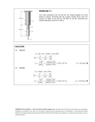
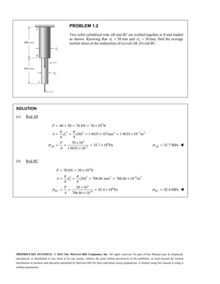
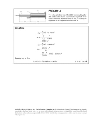
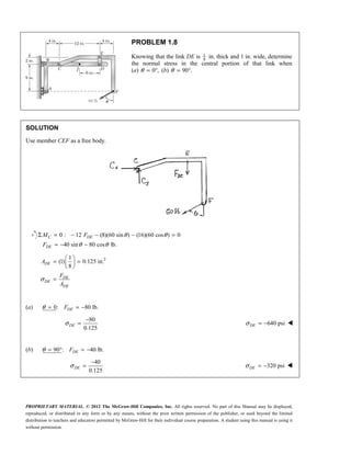
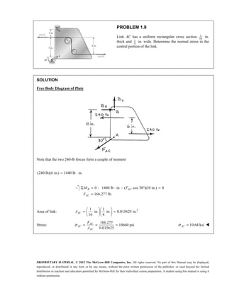
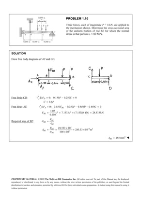
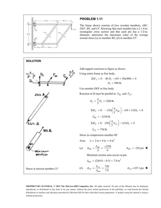
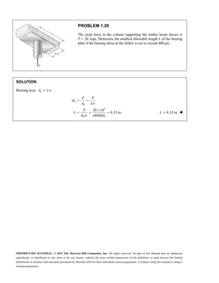
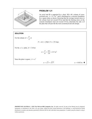
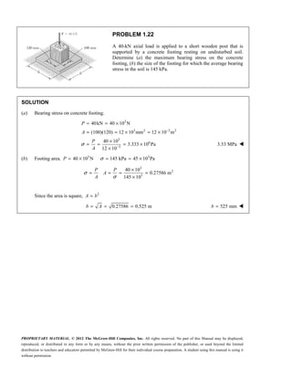
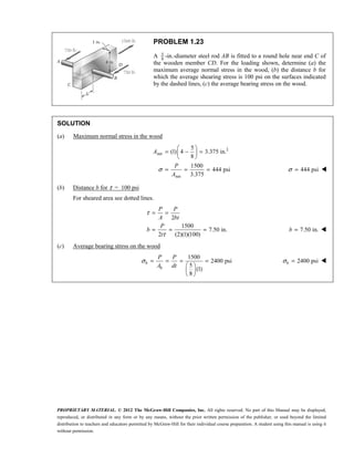
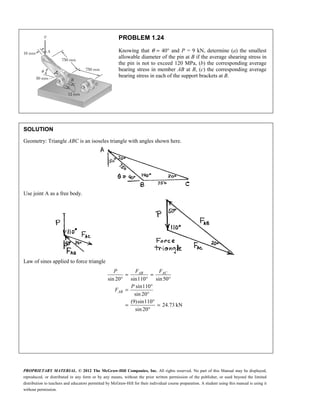
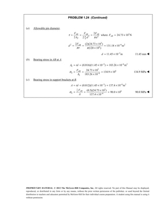
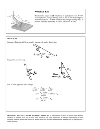
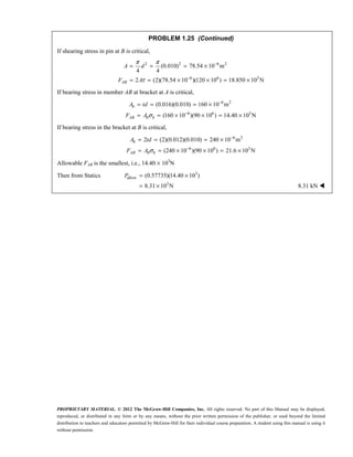
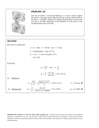
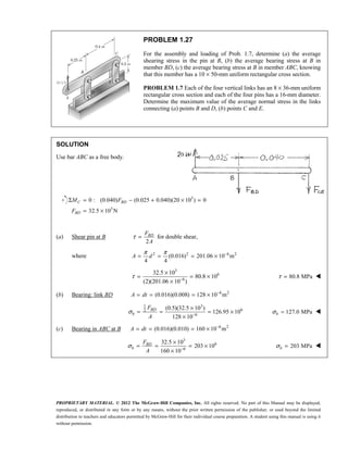
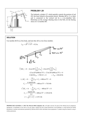
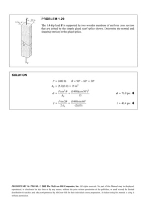
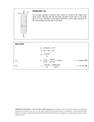
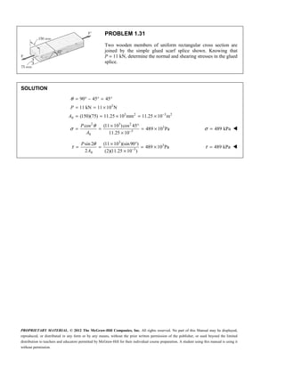
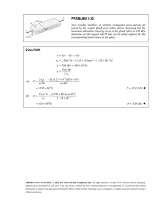
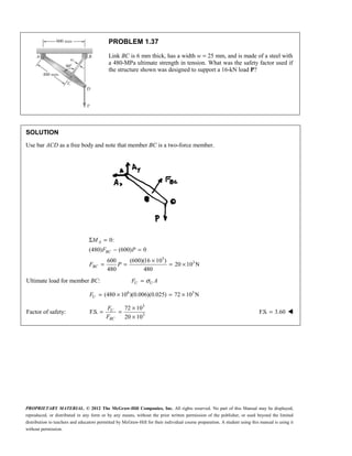
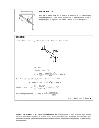
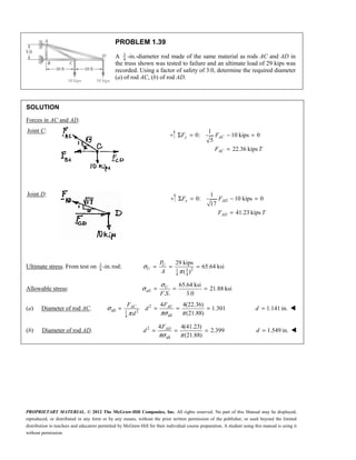
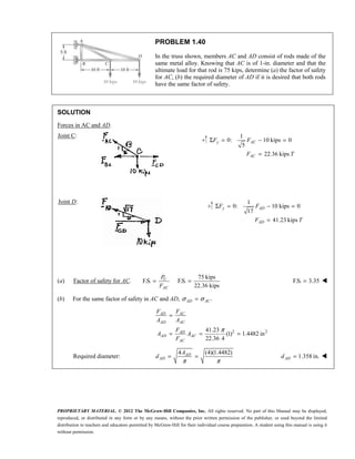
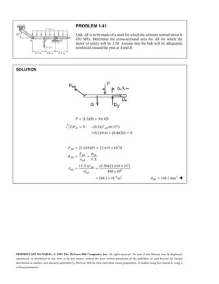
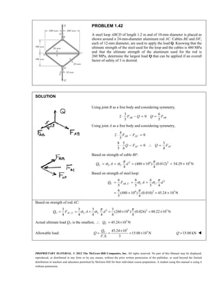
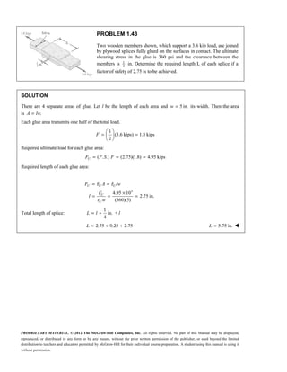
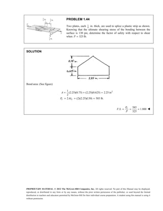
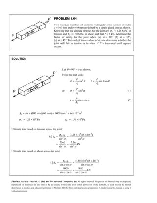
This document contains solutions to nine problems related to determining stresses in structural members. Problem 1 involves calculating the minimum diameters of two welded cylindrical rods based on given stress limits. Problem 2 finds the stresses in the rods when their diameters are specified. Later problems involve calculating stresses in other structural components like bolted plates, suspended rods, links in a truss, and more. Analytical equations are set up and solved for each problem to determine required dimensions, loads, or stresses. Diagrams are included to illustrate the free body diagrams used in some solutions.
This document contains solutions to physics problems involving statics. Problem 4.1 calculates the reactions at the rear and front wheels of a tractor lifting a load. Problem 4.2 determines the force needed on each handle of a wheelbarrow transporting a bag of fertilizer. Problem 4.3 finds the maximum distance from the wheelbarrow axle that a second bag can be placed. The remaining problems involve calculating reactions, tensions, and distances for various beams and loads. Free body diagrams and static equilibrium equations are used to solve for the unknown forces and distances in each problem.
This document contains solutions to 11 problems involving the calculation of stresses, strains, deformations in materials like wires, rods, and pipes when subjected to tensile loads. The problems apply concepts of stress, strain, modulus of elasticity, Hooke's law, and relationships between load, area, deformation and length to solve for values like maximum load or stress allowed, required material dimensions, elongation/deformation amounts. Calculations are shown involving steel, aluminum, nylon, brass and other materials. Diagrams or figures are not included - only the problem statements and mathematical solutions.
Ch06 07 pure bending & transverse shearDario Ch
This document contains chapter 6 from a textbook on mechanics of materials. It includes 13 multi-part example problems involving the calculation of shear and moment diagrams for beams and shafts subjected to different loading conditions. The problems cover statically determinate beams with various end supports and load configurations, including point loads, distributed loads, overhanging sections, and compound sections. The solutions show the application of the principles of equilibrium to draw shear and moment diagrams. Key steps include writing the shear and moment equations and evaluating the diagrams at specific locations.
This document contains solutions to multiple problems involving determining member forces in truss structures using the method of joints. The problems involve setting up force equilibrium equations at each joint to calculate the forces in each member. For every problem, the document shows the free body diagram of the entire truss and/or individual joints, writes the corresponding equilibrium equations, and solves for the member forces stating whether each member is in tension or compression.
Solutions manual for statics and mechanics of materials 5th edition by hibbel...zaezo
Solutions manual for statics and mechanics of materials 5th edition by hibbeler ibsn 9780134301006
download at: https://goo.gl/rTKRQ1
people also search:
hibbeler statics and mechanics of materials; 5th edition pdf
statics and mechanics of materials 5th edition pdf download
statics and mechanics of materials 5th edition ebook
statics and mechanics of materials 5th edition solutions pdf
statics and mechanics of materials hibbeler pdf download
statics and mechanics of materials solutions
hibbeler statics and mechanics of materials 4th edition pdf
statics and mechanics of materials 5th edition pdf free
The document discusses problems involving determining axial forces in truss members. Problem 6.7 describes a steel truss bridge with loads applied at various points. The axial forces in members AB, BC, BD, and BE are calculated. Problem 6.8 builds on 6.7 by determining the largest tensile and compressive forces that occur in the bridge truss members. Problem 6.9 considers changing the bridge design to a Howe truss and calculating the resulting largest tensile and compressive forces.
Mathematics for the Trades A Guided Approach Canadian 2nd Edition Carman Test...JudithLandrys
Full download : https://alibabadownload.com/product/mathematics-for-the-trades-a-guided-approach-canadian-2nd-edition-carman-test-bank/ Mathematics for the Trades A Guided Approach Canadian 2nd Edition Carman Test Bank
1) The document contains 4 engineering problems involving the calculation of stresses, forces, and deformations in mechanical structures under applied loads.
2) In problem 1, the normal stresses in the aluminum and brass layers of a composite bar are calculated.
3) Problem 2 determines the stresses in the steel core and aluminum shell of an assembly under compression, as well as the total deformation.
4) Problem 3 finds the change in length, stress, and distributed forces in three supporting rods with different cross-sectional areas.
5) The final problem calculates the reactions, stresses, and deflection at point C in a structure composed of steel and brass rods.
(1) The document presents several bending problems involving the determination of stress at various points on beams subjected to bending couples.
(2) Solutions are provided that calculate the stress based on the couple magnitude, beam geometry, and bending axis.
(3) Stresses are determined at points A, B, C, D, and E on different beams and range from -136 MPa to 91.7 MPa depending on the couple magnitude and distance from the beam's neutral axis.
This document provides solutions for determining the forces in members of truss structures. It analyzes trusses using the method of joints, applying equations of equilibrium at each joint to calculate member forces. For the truss shown, it determines that member FCD carries 5.21 kN of compression, FCB carries 2.36 kN of tension, and FAD carries 1.46 kN of compression.
Instructor solution manual for chapter 10 indeterminate structures "structur...Omar Daher
The document discusses the benefits of exercise for mental health. Regular physical activity can help reduce anxiety and depression and improve mood and cognitive functioning. Exercise causes chemical changes in the brain that may help boost feelings of calmness, happiness and focus.
Stress is defined as force per unit area. There are two main types of stress: normal stress and shear stress. Normal stress acts perpendicular to a surface, and can be tensile or compressive. Shear stress acts parallel to a surface. Stress is calculated based on the internal forces and the cross-sectional area. Design of structures requires restricting stresses to allowable levels using factors of safety to account for uncertainties. Connections must be designed so shear stresses do not exceed allowables.
1. The document describes a problem involving the elongation of a tapered bar made of plastic that has a hole drilled through part of its length and is under compressive loads at its ends.
2. It provides the dimensions, material properties, and loads and asks for the maximum diameter of the hole if the shortening of the bar is limited to 8 mm.
3. The solution sets up an equation for the shortening of the bar in terms of the hole diameter and substitutes the given values to solve for the maximum hole diameter of 23.9 mm.
This document contains solutions to 11 problems involving the calculation of stresses, strains, elongations, and required dimensions for structural members under tensile loading. The problems apply concepts of stress, strain, modulus of elasticity, and relationships between load, area, elongation and stress to analyze steel, aluminum, nylon and other materials. Diameters, cross-sectional areas, elongations, moduli of elasticity and stresses are calculated for wires, rods, pipes and other structural elements. Safety factors and allowable stresses are also incorporated into the analyses.
This document summarizes key concepts from Chapter 7 of the textbook "Mechanics of Materials" related to transformations of stress and strain. It introduces plane stress and strain, principal stresses and strains, Mohr's circle representation for analyzing stresses and strains under rotations. It provides examples and sample problems demonstrating how to determine principal stresses and strains, maximum shearing stresses, and stress/strain components under rotated reference frames using Mohr's circle. Diagrams and equations are presented for common stress/strain transformations.
Mechanics of Materials 9th Edition Hibbeler Solutions Manualpofojufyv
A tension test was performed on a steel specimen. The data is plotted on a stress-strain diagram. The modulus of elasticity is approximated as 30.0(103) ksi. The yield stress is approximated as 11.8 kip and the ultimate stress is approximated as 19.6 kip. These values are determined from the stress-strain diagram where the yield stress corresponds to a strain of 0.002 and the ultimate stress corresponds to the highest stress on the diagram.
This document contains 6 problems involving calculations of stress, strain, deflection and load capacity for mechanical structures composed of rods, beams, and wires under various loading conditions. The materials involved include steel, aluminum, brass and polystyrene. Deflections, elongations, average stresses and maximum supported loads are calculated using basic mechanics of materials equations relating force, stress, strain, modulus of elasticity and structural geometry.
This document contains solutions to 21 problems involving determining the resultant force of two or more applied forces using trigonometry and graphical methods. Many of the problems involve forces applied to structural members or supports. Trigonometric relationships like the Law of Sines and Law of Cosines are used to calculate the magnitude and direction of the resultant force. Detailed step-by-step workings are shown for each problem, with the final answers provided in vector form (magnitude and angle).
1) The document contains multiple problems involving determining reactions and forces in static equilibrium situations using free body diagrams and the equations of equilibrium.
2) Problem 5.16 involves determining the normal forces (H) at the hands and feet of a person doing a pushup based on his weight (W) and the given dimensions.
3) Problem 5.17 involves determining the reactions on a ladder from a 2000 N force exerted by a hydraulic piston.
Mechanics Of Fluids 4th Edition Potter Solutions Manualfexerona
This document provides solutions to problems in an instructor's manual for a textbook on fluid mechanics. It contains solutions for 14 problems from Chapter 1 which covers fundamental concepts like units, dimensions, density, viscosity, pressure and temperature relationships. The solutions include step-by-step working to arrive at the final numerical answer for each problem.
This document contains solutions to problems involving the calculation of shear stresses in beams. It determines shear stresses at specific points of beams by using the shear formula and calculating the shear force resisted by various beam components. The maximum shear stress in several beams is also calculated. Cross-sectional properties like moment of inertia are used. Shear stresses are indicated on volume elements and shear force diagrams are sketched.
The blocks and ladder problems can be summarized as follows:
1) The documents provide diagrams of blocks on inclined planes or ladders against walls, connected by cords or as single structures.
2) Frictional forces are calculated using coefficients of friction for each surface.
3) Force and moment sums are used to relate normal and frictional forces to weights, angles, and applied forces to determine minimum/maximum values for motion to occur.
This document provides an introduction to axial deformations in structural members under uniaxial loading. It discusses normal stress, shear stress, and bearing stress. It also covers strain, stress on inclined planes, and deformation of axially loaded members. Examples are provided to calculate stresses in pinned connections and determine stresses on inclined planes of a loaded bar. The key topics covered are stress definitions and calculations, Saint-Venant's principle, stress transformations on inclined planes, and introduction of strain as a measure of deformation.
The document describes the process of analyzing a truss structure using the method of joints. It provides two examples of solving for the forces in each member of a truss given applied loads. In both examples, the document first calculates the support reactions, then analyzes the force in each member by examining the equilibrium of forces at each joint. It is able to determine the force magnitude and whether each member is in tension or compression.
The document contains solutions to 325 problems related to torsion and torsional stress. The problems involve determining shear stresses, angles of twist, and diameters of circular or hollow shafts subjected to various torque loads. The solutions show calculations of shear stresses and angles of twist using the appropriate torsion equations and given material properties like shear modulus.
This document provides examples and problems related to static equilibrium of structures. Example 1 shows applying the equations of equilibrium to a weight suspended by a rope over a pulley. Example 2 calculates the forces in ropes supporting a weighted crate. Problem 3.7 asks the minimum force P needed for equilibrium of a crate supported by three ropes meeting at a point.
The document contains 11 multi-part solutions to problems from Chapter 5 of the textbook "Vector Mechanics for Engineers: Statics and Dynamics, 8th edition" by Ferdinand P. Beer, E. Russell Johnston, Jr., Elliot R. Eisenberg, William E. Clausen, David Mazurek, and Phillip J. Cornwell. Each solution finds the x-coordinate or y-coordinate of the centroid of one or more areas given dimensions and coordinates of the individual areas. Formulas for the centroid of standard shapes like triangles, circles, and semicircles are used to calculate the x- and y-coordinates of the centroid for the total area.
This document contains 20 multi-part engineering problems involving the calculation of shear and moment diagrams for beams and shafts. The problems include beams under various loading conditions such as point loads, distributed loads, overhanging sections, and compound sections. Shear and moment diagrams are drawn and the shear and moment values are calculated as functions of position along the members.
Ch08 10 combined loads & transformationsDario Ch
This document contains a table of contents for a textbook on mechanical engineering. The table of contents lists 14 chapters, beginning with "Stress" and ending with "Buckling of Columns". Each chapter is numbered and given a page range. The document provides an outline of the topics that will be covered in the textbook.
Solutions manual for mechanics of materials si 9th edition by hibbeler ibsn 9...jungkook11
This document provides solutions to problems in a mechanics of materials textbook. It gives step-by-step workings and calculations to determine things like average normal strain in materials like rubber strips or wires under various loads and configurations. The problems involve concepts like determining strain based on changes in length or displacement of points. The document contains solutions to 16 sample problems with diagrams and calculations shown.
This document contains chapter 6 from a textbook on mechanics of materials. It includes 13 multi-part example problems involving the calculation of shear and moment diagrams for beams and shafts subjected to different loading conditions. The problems cover statically determinate beams with various end supports and load configurations, including point loads, distributed loads, overhanging sections, and compound sections. The solutions show the application of the principles of equilibrium to draw shear and moment diagrams. Key steps include writing shear and moment equations and evaluating the diagrams at specific locations.
This document contains solutions to 11 problems involving the calculation of stresses, strains, elongations and dimensions of rods, wires and other structural elements under tensile loading conditions. The problems apply concepts of stress, strain, modulus of elasticity, Hooke's law and factor of safety to analyze steel, aluminum, nylon and other materials. The full solutions show the step-by-step working to determine values such as load, stress, elongation, diameter and length based on given material properties and loading/deformation parameters.
This document provides solutions to design problems involving simple stresses of tension, compression, and shear for various structural elements.
Problem 1 calculates the dimensions of a steel link subjected to tensile loading based on ultimate strength, yield strength, and a specified elongation limit. Problem 2 is similar but for a malleable iron link. Problem 3 calculates dimensions for a gray iron link based on ultimate strength and elongation.
Problem 4 calculates the diameter of a steel piston rod subjected to repeated reversed loading based on ultimate and yield strengths. Problem 5 calculates diameters for a short compression member made of cast steel. Problem 6 does the same for a member made of 4130 steel based on yield and ultimate strengths.
Problem 7 calculates the diameter
The document contains solutions to problems involving the determination of reaction forces in beams, trusses, and other structures using equations of equilibrium. The solutions involve writing force and moment equilibrium equations and solving the resulting simultaneous equations to determine the unknown reaction forces at supports. Components of the solutions are summarized as follows:
1) Free body diagrams are drawn showing the external forces acting on the structure.
2) Equilibrium equations are written for the forces and moments acting on the structure.
3) The equations are solved to determine values for the unknown reaction forces.
1) The document describes stress-strain diagrams from tensile tests on various materials including concrete, ceramics, steel, and alloys.
2) It provides data tables of load vs. strain measurements and asks the reader to plot stress-strain diagrams and determine values like modulus of elasticity, yield stress, and toughness.
3) Formulas are given for stress, strain, modulus of elasticity, and other mechanics of materials concepts as they relate to interpreting the stress-strain diagrams and tensile test data.
1) The document describes stress-strain diagrams from tensile tests on various materials including concrete, ceramics, steel, and alloys. It provides data on load, elongation, stress, and strain.
2) Methods for determining modulus of elasticity, modulus of resilience, modulus of toughness, yield stress, ultimate stress, and fracture stress from the stress-strain diagrams are presented.
3) Examples are given of using the data and diagrams to calculate various material properties including modulus of elasticity, yield load, elongation, and permanent set.
This document discusses reinforced concrete columns. It defines different types of columns including tied, spiral, composite, and steel pipe columns. It describes the behavior and analysis of axially loaded columns, including elastic behavior, creep effects, and nominal capacity. Design provisions from the ACI code are presented for reinforcement requirements of tied and spiral columns. The behavior of columns under combined bending and axial loads is discussed, including interaction diagrams. Examples are provided to demonstrate the design of columns for various load cases.
This document discusses analysis of statically determinate structures. It covers idealized structure representation, principles of superposition and equilibrium equations. Examples are provided to classify structures as determinate or indeterminate, determine stability, and calculate reactions on beams, frames and compound structures by applying equilibrium equations. Unknown reactions are solved for as force components at supports.
This document contains summaries of problems related to determining axial forces in truss members. The problems involve calculating forces based on free body diagrams and equilibrium equations for various truss structures under different loading conditions. The largest tensile force is found to occur in member FBE at 11.74 kips, while the largest compressive force occurs in member FBD at 42.5 kips for the bridge truss shown. Changing the design dimension h of another truss from 0.1m to 0.5m results in significant changes to the forces in members, with the maximum compressive force reducing from 2.78 kips to 1.54 kips.
solution manual Vector Mechanics for Engineers:Statics Beer Johnston Mazurek ...MichaelLeigh25
The document contains 18 practice problems involving determining the magnitude and direction of the resultant force of two or more applied forces using trigonometric methods like the law of sines and cosines. The problems involve forces applied to structures like hooks, brackets, stakes pulled from the ground, and tugboats pulling barges. The student must use trigonometry to calculate values like the unknown force magnitude, angle between forces, or magnitude of the resultant force.
Design of machine elements - DESIGN FOR SIMPLE STRESSESAkram Hossain
This document provides solutions to design problems involving the sizing of structural members based on their material properties and applied loads. Problem 1 involves sizing the cross-sectional dimensions of a steel link based on ultimate strength, yield strength, and allowable elongation. Problem 2 is similar but for a malleable iron link. Problem 3 considers a gray iron link. Subsequent problems involve sizing members made of various materials, including steel, cast steel, and bronze, based on factors like ultimate strength, yield strength, and applied tensile, compressive, and shear loads. Check problems 9-13 provide additional practice sizing members and calculating values like number of holes that can be punched or bearing length.
The document contains solutions to problems from Chapter 7 on slab analysis and friction in metal forming processes. Problem 7-1 calculates the power consumed in drawing a steel coil through a pair of dies. Problem 7-2 calculates the friction coefficient from an experimental rod drawing efficiency. Problem 7-3 estimates the force required to coin a quarter.
The document describes several problems involving the calculation of normal stress and strain in structural elements like posts, rods, wires, and beams. The problems involve circular and rectangular cross-sections under compression, tension or a combination of forces. Diagrams are provided and the geometry, forces and material properties are used to calculate stress, strain or unknown forces through equilibrium equations. Solutions show the relevant equations and step-by-step workings to arrive at the final numerical answers.
The document describes solutions to multiple problems involving calculating stress, strain, deflection, and elongation of rods and beams under various loads. The problems involve determining: (1) the elongation of a steel rod supported by a polystyrene cylinder and plate under a 3.2 kN load, (2) the total deformation of a composite steel and brass rod under separate loads, (3) the necessary force Q to make the deflection at the end of an aluminum rod zero under a 4 kN load P.
This document provides an introduction and overview of the concepts of stress and stress analysis from the textbook "Mechanics of Materials". It discusses stress, axial loading, shear stress, eccentric loading, bearing stress, and provides examples of calculating normal stress, shear stress, and bearing stress. The document also summarizes an example problem involving determining stresses in members and connections of a structural system subjected to an applied load.
This document provides an overview of the moment distribution method for analyzing statically indeterminate structures. It begins with introductions and definitions of key concepts like stiffness factors, distribution factors, and carry-over factors. It then outlines the step-by-step process of the method, which involves calculating fixed end moments, distributing moments at joints iteratively until convergence is reached, and determining shear forces and bending moments. Formulas are provided for prismatic beams. The document concludes by discussing how the method is adapted for non-prismatic members using design tables and graphs.
How to Manage Your Lost Opportunities in Odoo 17 CRMCeline George
Odoo 17 CRM allows us to track why we lose sales opportunities with "Lost Reasons." This helps analyze our sales process and identify areas for improvement. Here's how to configure lost reasons in Odoo 17 CRM
This slide is special for master students (MIBS & MIFB) in UUM. Also useful for readers who are interested in the topic of contemporary Islamic banking.
LAND USE LAND COVER AND NDVI OF MIRZAPUR DISTRICT, UPRAHUL
This Dissertation explores the particular circumstances of Mirzapur, a region located in the
core of India. Mirzapur, with its varied terrains and abundant biodiversity, offers an optimal
environment for investigating the changes in vegetation cover dynamics. Our study utilizes
advanced technologies such as GIS (Geographic Information Systems) and Remote sensing to
analyze the transformations that have taken place over the course of a decade.
The complex relationship between human activities and the environment has been the focus
of extensive research and worry. As the global community grapples with swift urbanization,
population expansion, and economic progress, the effects on natural ecosystems are becoming
more evident. A crucial element of this impact is the alteration of vegetation cover, which plays a
significant role in maintaining the ecological equilibrium of our planet.Land serves as the foundation for all human activities and provides the necessary materials for
these activities. As the most crucial natural resource, its utilization by humans results in different
'Land uses,' which are determined by both human activities and the physical characteristics of the
land.
The utilization of land is impacted by human needs and environmental factors. In countries
like India, rapid population growth and the emphasis on extensive resource exploitation can lead
to significant land degradation, adversely affecting the region's land cover.
Therefore, human intervention has significantly influenced land use patterns over many
centuries, evolving its structure over time and space. In the present era, these changes have
accelerated due to factors such as agriculture and urbanization. Information regarding land use and
cover is essential for various planning and management tasks related to the Earth's surface,
providing crucial environmental data for scientific, resource management, policy purposes, and
diverse human activities.
Accurate understanding of land use and cover is imperative for the development planning
of any area. Consequently, a wide range of professionals, including earth system scientists, land
and water managers, and urban planners, are interested in obtaining data on land use and cover
changes, conversion trends, and other related patterns. The spatial dimensions of land use and
cover support policymakers and scientists in making well-informed decisions, as alterations in
these patterns indicate shifts in economic and social conditions. Monitoring such changes with the
help of Advanced technologies like Remote Sensing and Geographic Information Systems is
crucial for coordinated efforts across different administrative levels. Advanced technologies like
Remote Sensing and Geographic Information Systems
9
Changes in vegetation cover refer to variations in the distribution, composition, and overall
structure of plant communities across different temporal and spatial scales. These changes can
occur natural.
How to Fix the Import Error in the Odoo 17Celine George
An import error occurs when a program fails to import a module or library, disrupting its execution. In languages like Python, this issue arises when the specified module cannot be found or accessed, hindering the program's functionality. Resolving import errors is crucial for maintaining smooth software operation and uninterrupted development processes.
A workshop hosted by the South African Journal of Science aimed at postgraduate students and early career researchers with little or no experience in writing and publishing journal articles.
A review of the growth of the Israel Genealogy Research Association Database Collection for the last 12 months. Our collection is now passed the 3 million mark and still growing. See which archives have contributed the most. See the different types of records we have, and which years have had records added. You can also see what we have for the future.
How to Add Chatter in the odoo 17 ERP ModuleCeline George
In Odoo, the chatter is like a chat tool that helps you work together on records. You can leave notes and track things, making it easier to talk with your team and partners. Inside chatter, all communication history, activity, and changes will be displayed.
The simplified electron and muon model, Oscillating Spacetime: The Foundation...RitikBhardwaj56
Discover the Simplified Electron and Muon Model: A New Wave-Based Approach to Understanding Particles delves into a groundbreaking theory that presents electrons and muons as rotating soliton waves within oscillating spacetime. Geared towards students, researchers, and science buffs, this book breaks down complex ideas into simple explanations. It covers topics such as electron waves, temporal dynamics, and the implications of this model on particle physics. With clear illustrations and easy-to-follow explanations, readers will gain a new outlook on the universe's fundamental nature.