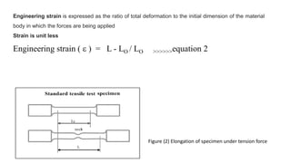
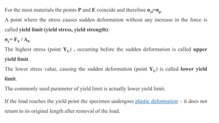
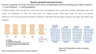
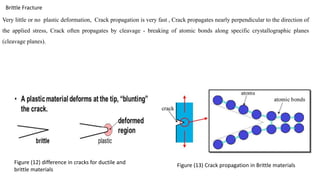
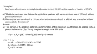
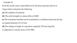
The document discusses materials testing and various types of tests, including destructive and non-destructive tests. Destructive tests include tensile tests, compression tests, torsion tests, impact tests, hardness tests, fatigue tests, and creep tests. Non-destructive tests include scanning electron microscopy, radiography, atomic force microscopy, liquid penetration testing, and ultrasonic testing. The document focuses on tensile tests and provides details on how they are conducted, what properties they measure (e.g. yield strength, ultimate tensile strength, modulus of elasticity), and how to interpret stress-strain curves. Examples of calculations using data from tensile tests are also provided.
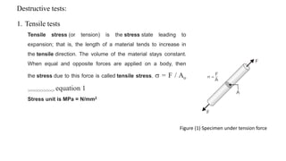
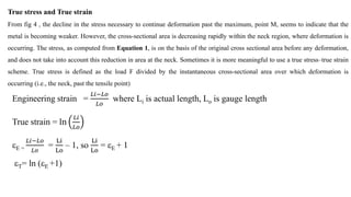
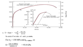
![Engineering stress E = F / Ao where Ao is original area
True stress (T) = F/ Ai , where Ai is the area where the fracture occurring at the necking region
Since the volume is constant Ao L0 = Ai Li >>>>> Ai = [
Li
Lo
] / Ao
T = F/ Ai =
F
Ao
[
Li
Lo
]
T = E (E +1)
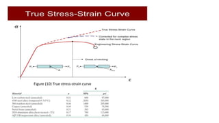
For some metals and alloys, the region of the true stress/ strain curve up to M’ is approximated by:
T = K T
n
Where K and n are constants depend on whether the material has been cold worked, heat treated, etc](https://image.slidesharecdn.com/520180327121805pm-230713160450-cd68c897/85/stress-strain-pptx-15-320.jpg)
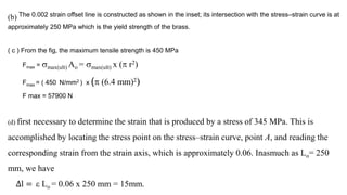
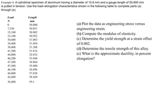
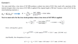
![Example 3:
A cylindrical specimen of steel having an original diameter of 12.8 mm is tensile tested to fracture and found to
have an engineering fracture strength of 460 MPa. If its cross-sectional diameter at fracture is 10.7 mm,
determine:
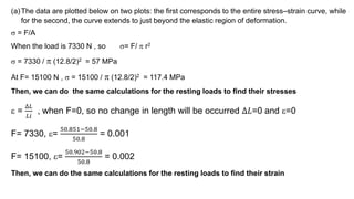
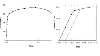
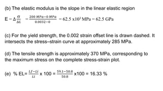
(a) The ductility in terms of percent reduction in area
(b) The true stress at fracture
(a) % RA= (Ao-Af / A0 ) x 100
%RA=
{
12.8
2
2−
10.7
2
2}
(10.7/2)2
x 100 = 30%
(b) True stress is defined the area is taken as the fracture area Af However, the load at fracture must
first be computed from the fracture strength as
F = f Ai = 460 MPa x [ (12.8/2 mm)2] = 59200 N
f represents engineering stress E which is determined using the initial area
T = F / Af
T = 59200/ (10.7/2)2
T = 660 MPa](https://image.slidesharecdn.com/520180327121805pm-230713160450-cd68c897/85/stress-strain-pptx-23-320.jpg)