This document contains chapter 6 from a textbook on mechanics of materials. It includes 13 multi-part example problems involving the calculation of shear and moment diagrams for beams and shafts subjected to different loading conditions. The problems cover statically determinate beams with various end supports and load configurations, including point loads, distributed loads, overhanging sections, and compound sections. The solutions show the application of the principles of equilibrium to draw shear and moment diagrams. Key steps include writing the shear and moment equations and evaluating the diagrams at specific locations.
![356
Section Properties:
Maximum Bending Stress: Applying the flexure formula
Ans.M = 129.2 kip # in = 10.8 kip # ft
10 =
M (10.5 - 3.4)
91.73
smax =
Mc
I
= 91.73 in4
+
1
12
(0.5)A103
B + 0.5(10)(5.5 - 3.40)2
+ 2c
1
12
(0.5)(33
) + 0.5(3)(3.40 - 2)2
d
INA =
1
12
(4)A0.53
B + 4(0.5)(3.40 - 0.25)2
=
0.25(4)(0.5) + 2[2(3)(0.5)] + 5.5(10)(0.5)
4(0.5) + 2[(3)(0.5)] + 10(0.5)
= 3.40 in.
y =
© y A
©A
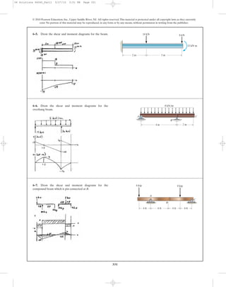
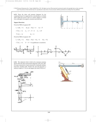
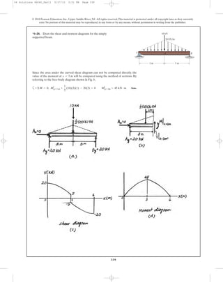
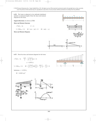
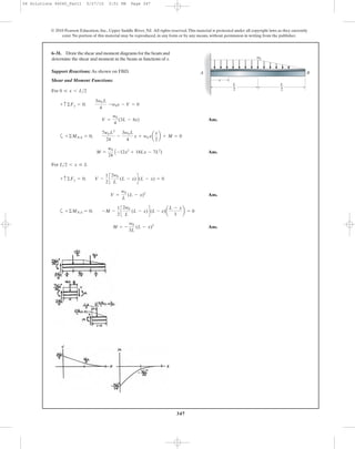
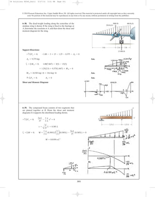
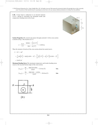
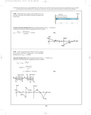
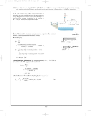
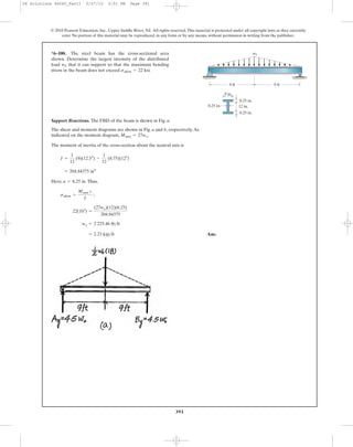
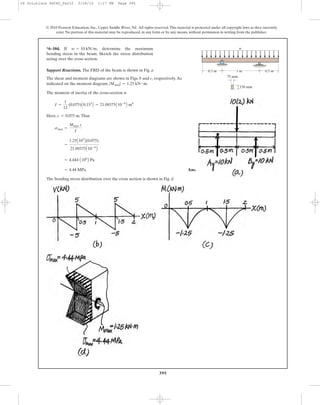
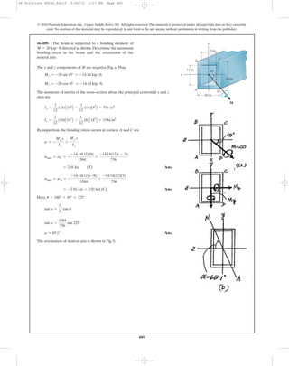
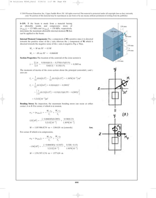
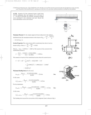
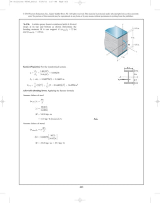
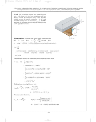
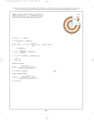
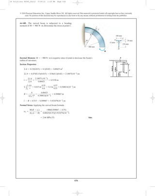
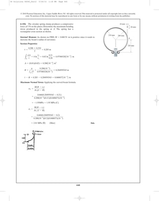
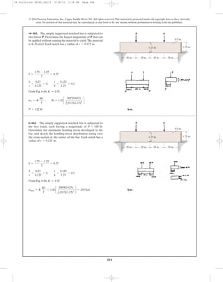
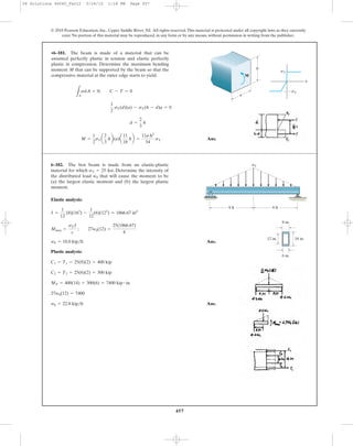
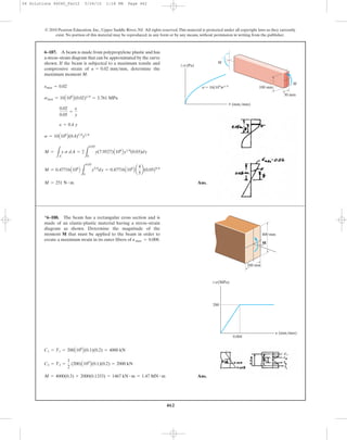
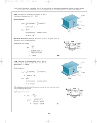
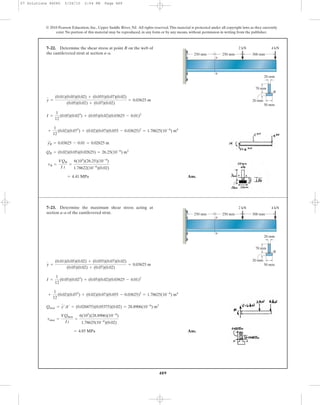
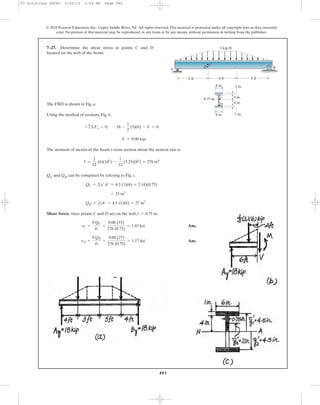
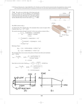
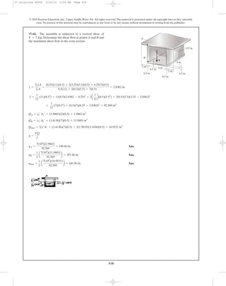
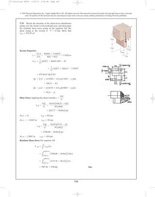
*6–48. Determine the moment M that will produce a
maximum stress of 10 ksi on the cross section.
© 2010 Pearson Education, Inc., Upper Saddle River, NJ. All rights reserved.This material is protected under all copyright laws as they currently
exist. No portion of this material may be reproduced, in any form or by any means, without permission in writing from the publisher.
3 in.
D
A B
0.5 in.
M
0.5 in.
3 in.
C
10 in.
0.5 in.0.5 in.
06 Solutions 46060_Part1 5/27/10 3:51 PM Page 356](https://image.slidesharecdn.com/ch06-07purebendingtransverseshear-180519192449/85/Ch06-07-pure-bending-amp-transverse-shear-29-320.jpg)
![357
Section Properties:
Maximum Bending Stress: Applying the flexure formula
Ans.
Ans.(sc)max =
4(103
)(12)(3.40)
91.73
= 1779.07 psi = 1.78 ksi
(st)max =
4(103
)(12)(10.5 - 3.40)
91.73
= 3715.12 psi = 3.72 ksi
smax =
Mc
I
= 91.73 in4
+
1
12
(0.5)A103
B + 0.5(10)(5.5 - 3.40)2
+ 2c
1
12
(0.5)(33
) + 0.5(3)(3.40 - 2)2
d
INA =
1
12
(4)A0.53
B + 4(0.5)(3.40 - 0.25)2
=
0.25(4)(0.5) + 2[2(3)(0.5)] + 5.5(10)(0.5)
4(0.5) + 2[(3)(0.5)] + 10(0.5)
= 3.40 in.
y =
© y A
©A
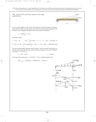
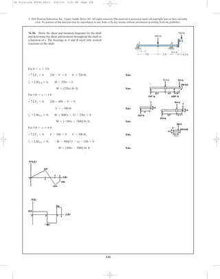
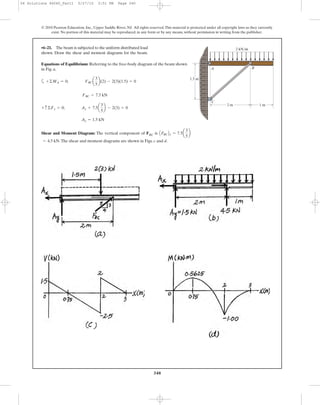
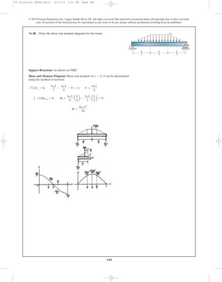
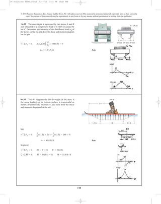
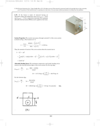
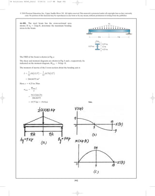
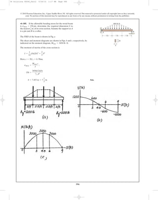
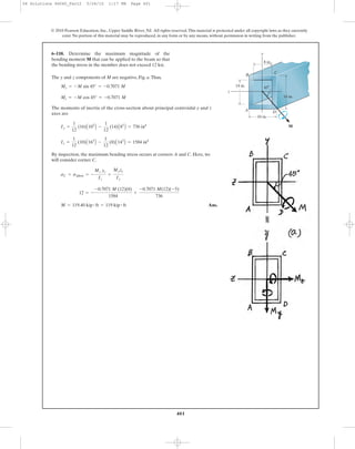
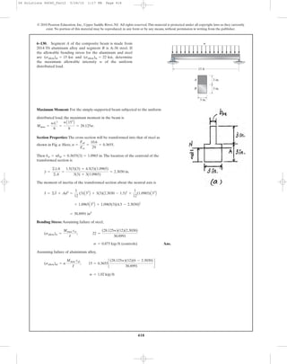
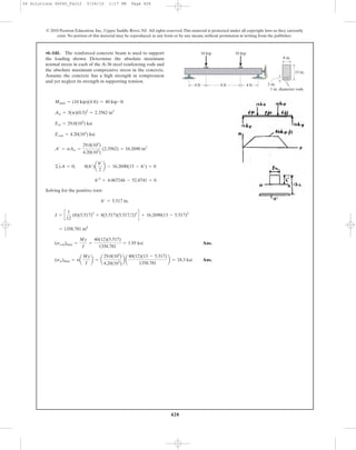
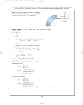
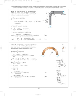
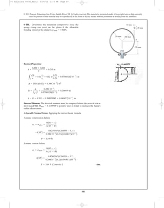
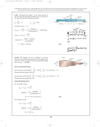
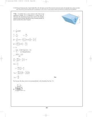
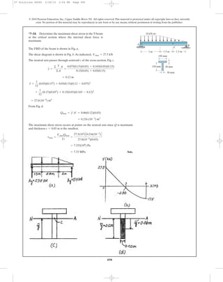
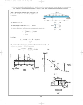
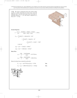
•6–49. Determine the maximum tensile and compressive
bending stress in the beam if it is subjected to a moment of
M = 4 kip # ft.
© 2010 Pearson Education, Inc., Upper Saddle River, NJ. All rights reserved.This material is protected under all copyright laws as they currently
exist. No portion of this material may be reproduced, in any form or by any means, without permission in writing from the publisher.
3 in.
D
A B
0.5 in.
M
0.5 in.
3 in.
C
10 in.
0.5 in.0.5 in.
06 Solutions 46060_Part1 5/27/10 3:51 PM Page 357](https://image.slidesharecdn.com/ch06-07purebendingtransverseshear-180519192449/85/Ch06-07-pure-bending-amp-transverse-shear-30-320.jpg)
![358
Ans.
Ans.sB =
30(13.24 - 10)(10-3
)
0.095883(10-6
)
= 1.01 MPa
sA =
30(35 - 13.24)(10-3
)
0.095883(10-6
)
= 6.81 MPa
= 0.095883(10-6
) m4
+ 2c
1
12
(5)(203
) + 5(20)(20 - 13.24)2
d + 2c
1
12
(12)(53
) + 12(5)(32.5 - 13.24)2
d
+ c
1
12
(34)(53
) + 34(5)(13.24 - 7.5)2
d
I = c
1
12
(50)(53
) + 50(5)(13.24 - 2.5)2
d
= 13.24 mm
y =
2.5(50)(5) + 7.5(34)(5) + 2[20(5)(20)] + 2[(32.5)(12)(5)]
50(5) + 34(5) + 2[5(20)] + 2[(12)(5)]
Ans.
Ans.M = 771 N # m
s =
Mc
I
; 175(106
) =
M(35 - 13.24)(10-3
)
0.095883(10-6
)
= 0.095883(10-6
) m4
+ 2c
1
12
(5)(203
) + 5(20)(20 - 13.24)2
d + 2c
1
12
(12)(53
) + 12(5)(32.5 - 13.24)2
d
I = c
1
12
(50)(53
) + 50(5)(13.24 - 2.5)2
d + c
1
12
(34)(53
) + 34(5)(13.24 - 7.5)2
d
y =
©y2
A
©A
=
2.5(50)(5) + 7.5(34)(5) + 2[20(5)(20)] + 2[(32.5)(12)(5)]
50(5) + 34(5) + 2[5(20)] + 2[(12)(5)]
= 13.24 mm
sC =
30(13.24)(10-3
)
0.095883(10-6
)
= 4.14 MPa
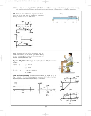
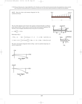
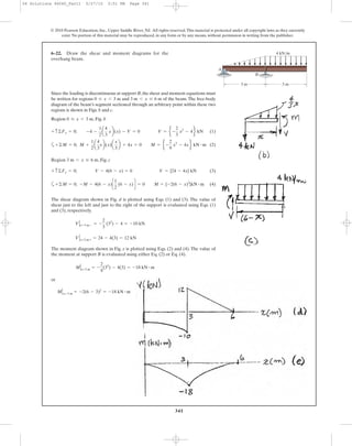
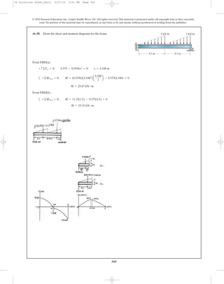
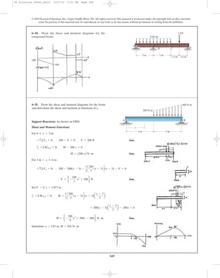
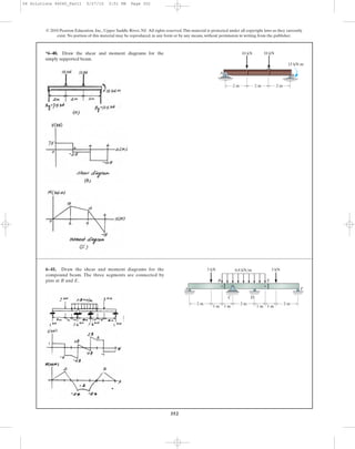
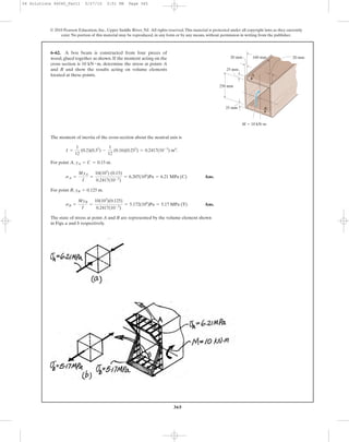
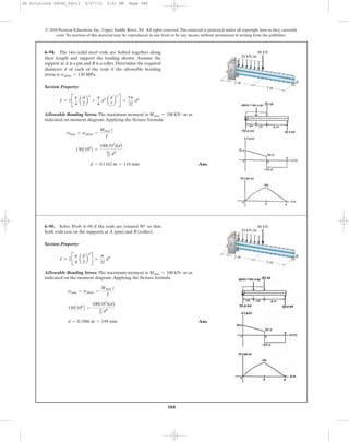
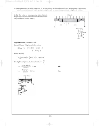
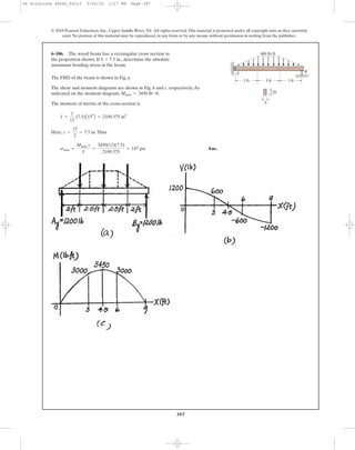
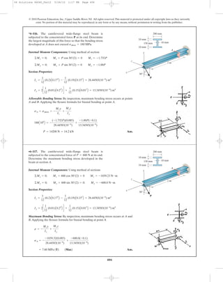
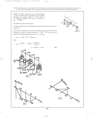
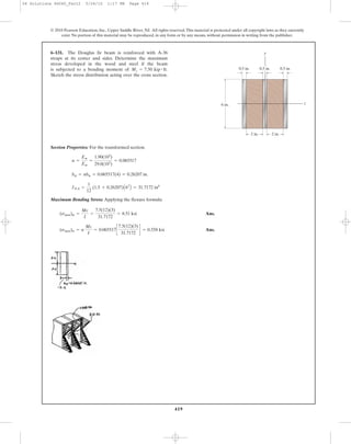
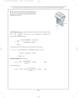
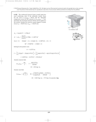
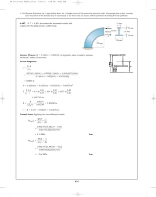
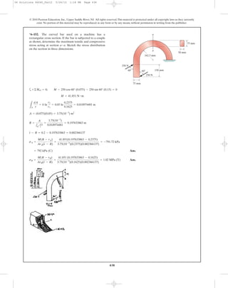
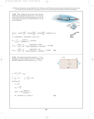
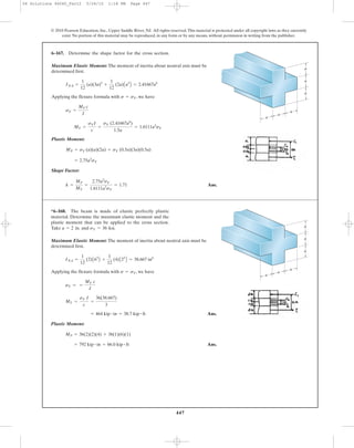
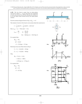
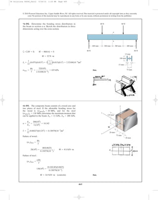
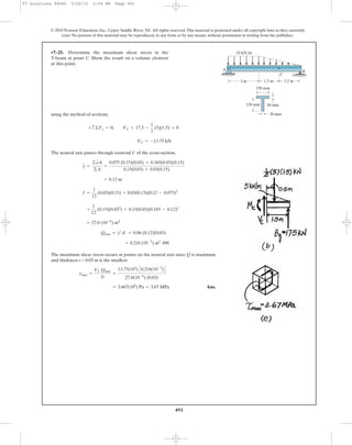
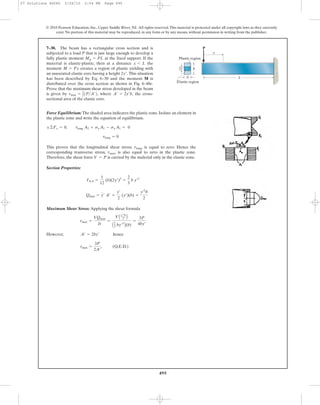
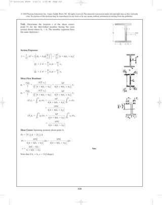
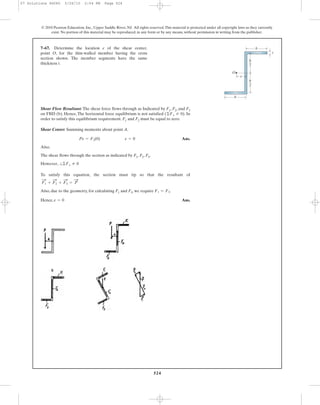
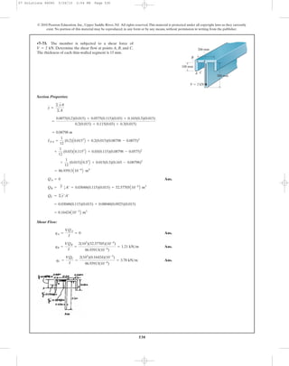
6–50. The channel strut is used as a guide rail for a trolley.
If the maximum moment in the strut is
determine the bending stress at points A, B, and C.
M = 30 N # m,
6–51. The channel strut is used as a guide rail for a
trolley. If the allowable bending stress for the material is
determine the maximum bending moment
the strut will resist.
sallow = 175 MPa,
© 2010 Pearson Education, Inc., Upper Saddle River, NJ. All rights reserved.This material is protected under all copyright laws as they currently
exist. No portion of this material may be reproduced, in any form or by any means, without permission in writing from the publisher.
50 mm
30 mm
A
B
C
5 mm
5 mm
5 mm
5 mm
5 mm
7 mm 7 mm10 mm
50 mm
30 mm
A
B
C
5 mm
5 mm
5 mm
5 mm
5 mm
7 mm 7 mm10 mm
06 Solutions 46060_Part1 5/27/10 3:51 PM Page 358](https://image.slidesharecdn.com/ch06-07purebendingtransverseshear-180519192449/85/Ch06-07-pure-bending-amp-transverse-shear-31-320.jpg)
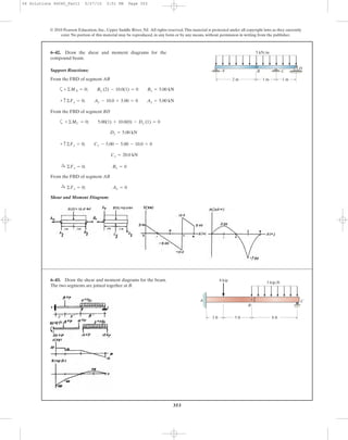
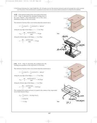
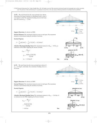
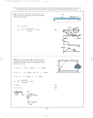
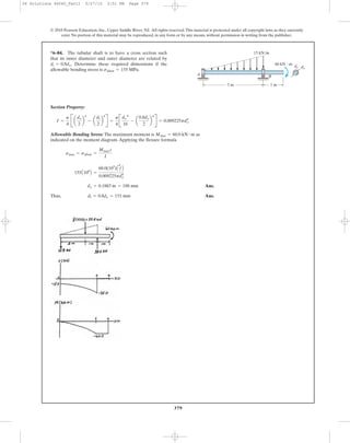
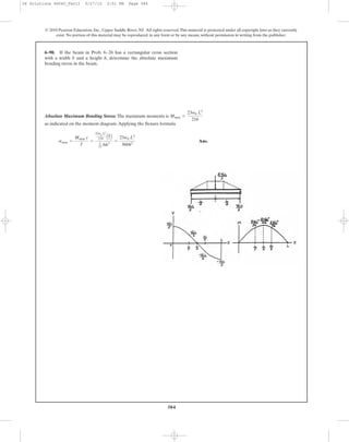
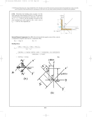
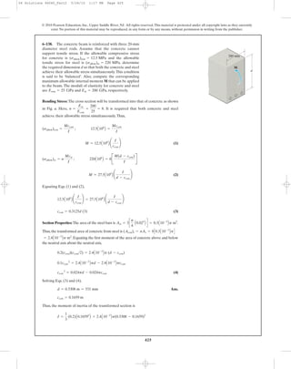
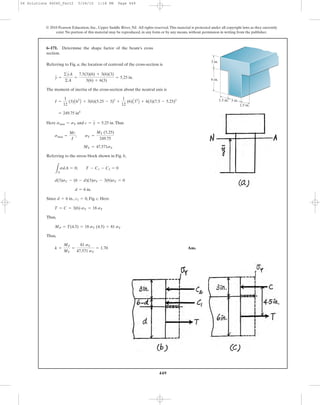
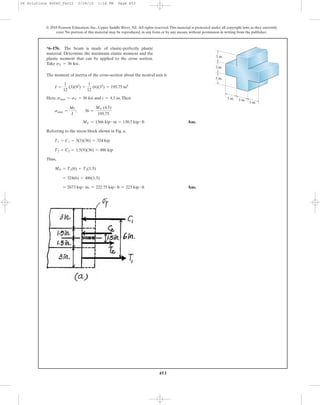
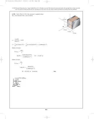
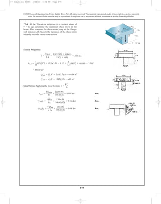
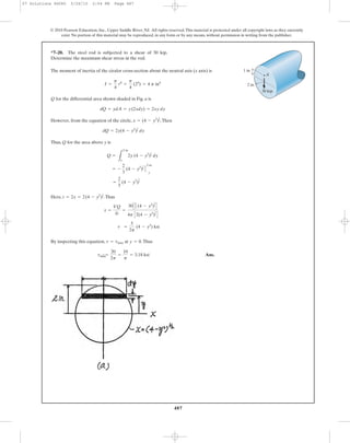
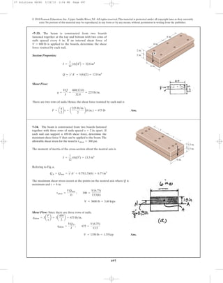
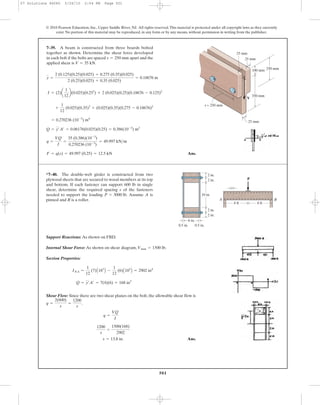
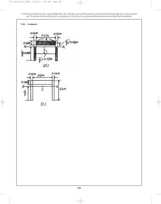
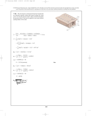
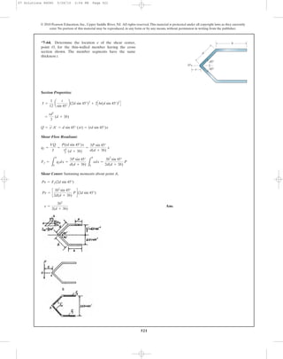
![•6–61. The beam is constructed from four boards as shown.
If it is subjected to a moment of determine
the resultant force the stress produces on the top board C.
Mz = 16 kip # ft,
364
*6–60. The beam is constructed from four boards as
shown. If it is subjected to a moment of
determine the stress at points A and B. Sketch a
three-dimensional view of the stress distribution.
Mz = 16 kip # ft,
© 2010 Pearson Education, Inc., Upper Saddle River, NJ. All rights reserved.This material is protected under all copyright laws as they currently
exist. No portion of this material may be reproduced, in any form or by any means, without permission in writing from the publisher.
10 in.
10 in.
1 in.
14 in.
1 in.
1 in.
Mz ϭ 16 kipиft
y
z
x
1 in.
A
C
B
10 in.
10 in.
1 in.
14 in.
1 in.
1 in.
Mz ϭ 16 kipиft
y
z
x
1 in.
A
C
B
Ans.
Ans.sB =
My
I
=
16(12)(9.3043)
1093.07
= 1.63 ksi
sA =
Mc
I
=
16(12)(21 - 9.3043)
1093.07
= 2.05 ksi
+
1
12
(1)(103
) + 1(10)(16 - 9.3043)2
= 1093.07 in4
I = 2c
1
12
(1)(103
) + 1(10)(9.3043 - 5)2
d +
1
12
(16)(13
) + 16(1)(10.5 - 9.3043)2
= 9.3043 in.
y =
2[5(10)(1)] + 10.5(16)(1) + 16(10)(1)
2(10)(1) + 16(1) + 10(1)
Ans.(FR)C =
1
2
(2.0544 + 0.2978)(10)(1) = 11.8 kip
sD =
My
I
=
16(12)(11 - 9.3043)
1093.07
= 0.2978 ksi
sA =
Mc
I
=
16(12)(21 - 9.3043)
1093.07
= 2.0544 ksi
+
1
12
(1)(103
) + 1(10)(16 - 9.3043)2
= 1093.07 in4
I = 2c
1
12
(1)(103
) + (10)(9.3043 - 5)2
d +
1
12
(16)(13
) + 16(1)(10.5 - 9.3043)2
y =
2[5(10)(1)] + 10.5(16)(1) + 16(10)(1)
2(10)(1) + 16(1) + 10(1)
= 9.3043 in.
06 Solutions 46060_Part1 5/27/10 3:51 PM Page 364](https://image.slidesharecdn.com/ch06-07purebendingtransverseshear-180519192449/85/Ch06-07-pure-bending-amp-transverse-shear-37-320.jpg)
![398
Location of neutral axis:
[1]
Taking positive root:
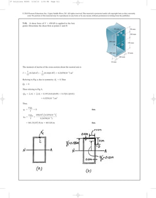
[2] Ans.
From Eq. [1].
From Eq. [2]
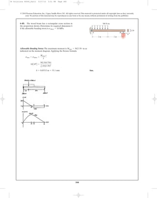
Ans.(smax)t =
3M
b h2
£
2Et + 2Ec
2Ec
≥
M =
1
3
bc(smax)t (h - c + c) ; (smax)t =
3M
bhc
M =
1
3
(h - c)2
(b)a
c
h - c
b(smax)t +
1
3
c2
b(smax)t
(smax)c =
c
h - c
(smax)t
M =
1
3
(h - c)2
(b)(smax)c +
1
3
c2
b(smax)t
M = c
1
2
(h - c)(smax)c (b)d a
2
3
b(h - c) + c
1
2
(c)(smax)t(b) d a
2
3
b(c)
©MNA = 0;
c =
h
A
Ec
Et
1 +
A
Ec
Et
=
h2Ec
2Et + 2Ec
c
h - c
=
A
Ec
Et
(h - c)Ec (emax)t
(h - c)
c
= cEt (emax)t ; Ec (h - c)2
= Etc2
(h - c)(smax)c = c(smax)t
©F = 0; -
1
2
(h - c)(smax)c (b) +
1
2
(c)(smax)t (b) = 0:+
(smax)c = Ec(emax)c =
Ec(emax)t (h - c)
c
(emax)c =
(emax)t (h - c)
c
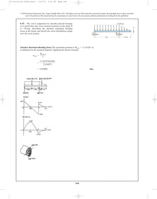
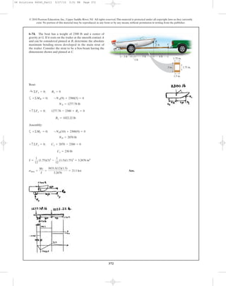
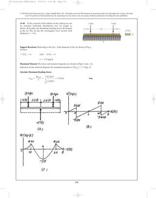
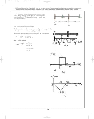
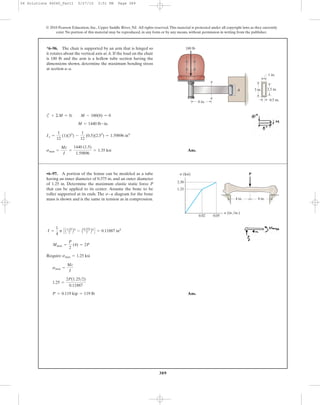
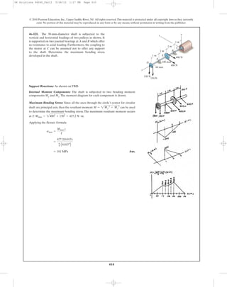
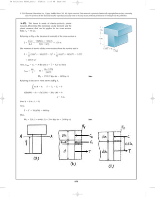
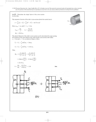
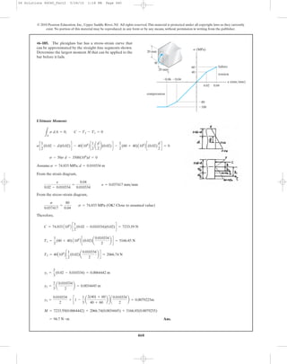
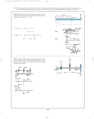
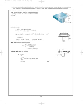
6–107. A beam is made of a material that has a modulus of
elasticity in compression different from that given for
tension. Determine the location c of the neutral axis, and
derive an expression for the maximum tensile stress in the
beam having the dimensions shown if it is subjected to the
bending moment M.
© 2010 Pearson Education, Inc., Upper Saddle River, NJ. All rights reserved.This material is protected under all copyright laws as they currently
exist. No portion of this material may be reproduced, in any form or by any means, without permission in writing from the publisher.
h
c
bEt
Ec
M
s
P
06 Solutions 46060_Part2 5/26/10 1:17 PM Page 398](https://image.slidesharecdn.com/ch06-07purebendingtransverseshear-180519192449/85/Ch06-07-pure-bending-amp-transverse-shear-71-320.jpg)
![402
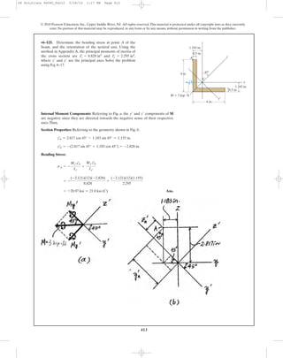
Internal Moment Components:
Section Properties:
Ans.
Maximum Bending Stress: Applying the flexure formula for biaxial at points A
and B
Ans.
Ans.
Orientation of Neutral Axis:
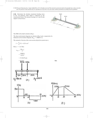
Ans.a = -3.74°
tan a =
57.6014(10-6
)
0.366827(10-3
)
tan (-22.62°)
tan a =
Iz
Iy
tan u
= 0.587 MPa (T)
sB = -
-480(0.057368)
57.6014(10-6
)
+
200(0.2)
0.366827(10-3
)
= -1.298 MPa = 1.30 MPa (C)
sA = -
-480(-0.142632)
57.6014(10-6
)
+
200(-0.2)
0.366827(10-3
)
s = -
Mzy
Iz
+
Myz
Iy
Iy =
1
12
(0.2)A0.43
B -
1
12
(0.18)A0.363
B = 0.366827A10-3
B m4
= 57.6014A10-6
B m4
+
1
12
(0.04)A0.183
B + 0.04(0.18)(0.110 - 0.057368)2
Iz =
1
12
(0.4)A0.023
B + (0.4)(0.02)(0.057368 - 0.01)2
= 0.057368 m = 57.4 mm
y =
©yA
©A
=
0.01(0.4)(0.02) + 2[(0.110)(0.18)(0.02)]
0.4(0.02) + 2(0.18)(0.02)
Mz = -
12
13
(520) = -480 N # m My =
5
13
(520) = 200 N # m
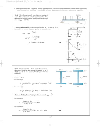
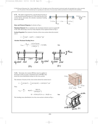
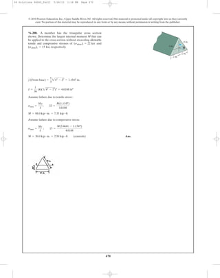
6–111. If the resultant internal moment acting on the
cross section of the aluminum strut has a magnitude of
and is directed as shown, determine the
bending stress at points A and B. The location of the
centroid C of the strut’s cross-sectional area must be
determined.Also, specify the orientation of the neutral axis.
y
M = 520 N # m
© 2010 Pearson Education, Inc., Upper Saddle River, NJ. All rights reserved.This material is protected under all copyright laws as they currently
exist. No portion of this material may be reproduced, in any form or by any means, without permission in writing from the publisher.
20 mm20 mm
z
B
C
–y
200 mm
y
M ϭ 520 Nиm
12
5 13
200 mm 200 mm
A
20 mm
06 Solutions 46060_Part2 5/26/10 1:17 PM Page 402](https://image.slidesharecdn.com/ch06-07purebendingtransverseshear-180519192449/85/Ch06-07-pure-bending-amp-transverse-shear-75-320.jpg)
![403
© 2010 Pearson Education, Inc., Upper Saddle River, NJ. All rights reserved.This material is protected under all copyright laws as they currently
exist. No portion of this material may be reproduced, in any form or by any means, without permission in writing from the publisher.
Internal Moment Components:
Section Properties:
Ans.
Maximum Bending Stress: By inspection, the maximum bending stress can occur at
either point A or B. Applying the flexure formula for biaxial bending at points A
and B
Ans.
Orientation of Neutral Axis:
Ans.a = -3.74°
tan a =
57.6014(10-6
)
0.366827(10-3
)
tan (-22.62°)
tan a =
Iz
Iy
tan u
= 0.587 MPa (T)
sB = -
-480(0.057368)
57.6014(10-6
)
+
200(0.2)
0.366827(10-3
)
= -1.298 MPa = 1.30 MPa (C) (Max)
sA = -
-480(-0.142632)
57.6014(10-6
)
+
200(-0.2)
0.366827(10-3
)
s = -
Mz y
Iz
+
My z
Iy
Iy =
1
12
(0.2)A0.43
B -
1
12
(0.18)A0.363
B = 0.366827A10-3
B m4
= 57.6014A10-6
B m4
+
1
12
(0.04)A0.183
B + 0.04(0.18)(0.110 - 0.057368)2
Iz =
1
12
(0.4)A0.023
B + (0.4)(0.02)(0.057368 - 0.01)2
= 0.057368 m = 57.4 mm
y =
© y A
©A
=
0.01(0.4)(0.02) + 2[(0.110)(0.18)(0.02)]
0.4(0.02) + 2(0.18)(0.02)
Mz = -
12
13
(520) = -480 N # m My =
5
13
(520) = 200 N # m
*6–112. The resultant internal moment acting on the
cross section of the aluminum strut has a magnitude of
and is directed as shown. Determine
maximum bending stress in the strut. The location of the
centroid C of the strut’s cross-sectional area must be
determined.Also, specify the orientation of the neutral axis.
y
M = 520 N # m
20 mm20 mm
z
B
C
–y
200 mm
y
M ϭ 520 Nиm
12
5 13
200 mm 200 mm
A
20 mm
06 Solutions 46060_Part2 5/26/10 1:17 PM Page 403](https://image.slidesharecdn.com/ch06-07purebendingtransverseshear-180519192449/85/Ch06-07-pure-bending-amp-transverse-shear-76-320.jpg)
![404
© 2010 Pearson Education, Inc., Upper Saddle River, NJ. All rights reserved.This material is protected under all copyright laws as they currently
exist. No portion of this material may be reproduced, in any form or by any means, without permission in writing from the publisher.
Equilibrium Condition:
[1]
[2]
[3]
Section Properties: The integrals are defined in Appendix A. Note that
.Thus,
From Eq. [1]
From Eq. [2]
From Eq. [3]
Solving for a, b, c:
Thus, (Q.E.D.)sx = - ¢
Mz Iy + My Iyz
Iy Iz - Iyz
2 ≤y + ¢
My Iy + MzIyz
Iy Iz - Iyz
2 ≤z
b = - ¢
MzIy + My Iyz
Iy Iz - Iyz
2 ≤ c =
My Iz + Mz Iyz
Iy Iz - Iyz
2
a = 0 (Since A Z 0)
Mz = -bIz - cIyz
My = bIyz + cIy
Aa = 0
LA
y dA =
LA
z dA = 0
= -a
LA
ydA - b
LA
y2
dA - c
LA
yz dA
=
LA
-y(a + by + cz) dA
Mz =
LA
-y sx dA
= a
LA
z dA + b
LA
yz dA + c
LA
z2
dA
=
LA
z(a + by + cz) dA
My =
LA
z sx dA
0 = a
LA
dA + b
LA
y dA + c
LA
z dA
0 =
LA
(a + by + cz) dA
0 =
LA
sx dA
sx = a + by + cz
6–113. Consider the general case of a prismatic beam
subjected to bending-moment components and
as shown, when the x, y, z axes pass through the centroid
of the cross section. If the material is linear-elastic, the
normal stress in the beam is a linear function of position
such that Using the equilibrium con-
ditions
determine the constants a, b, and c, and show that the
normal stress can be determined from the equation
where the moments and products of inertia are defined in
Appendix A.
s = [-1MzIy + MyIyz2y + 1MyIz + MzIyz2z]>1IyIz - Iyz
2
2,
1A - ys dA,Mz =My = 1A zs dA,0 = 1As dA,
s = a + by + cz.
Mz,My
y
y
z x
z
dA
My
C
Mz
s
06 Solutions 46060_Part2 5/26/10 1:17 PM Page 404](https://image.slidesharecdn.com/ch06-07purebendingtransverseshear-180519192449/85/Ch06-07-pure-bending-amp-transverse-shear-77-320.jpg)
 + [(4.80)(103
)(2.970378) + 0](2.125)}
[1.60319(2.970378) - (1.6875)2
]
s = - a
Mz Iy + My Iyz
Iy Iz - Iyz
2
by + a
My Iz + Mz Iyz
Iy Iz - Iyz
2
bz
Iyz = 2[1.5(1.125)(2)(0.25)] = 1.6875 in4
Iz =
1
12
(0.25)(3.25)3
+ 2c
1
12
(2)(0.25)3
+ (0.25)(2)(1.5)2
d = 2.970378 in4
Iy =
1
12
(3.25)(0.25)3
+ 2c
1
12
(0.25)(2)3
+ (0.25)(2)(1.125)2
d = 1.60319 in4
(My)max = 50(3) + 50(5) = 400 lb # ft = 4.80(103
)lb # in.
6–114. The cantilevered beam is made from the Z-section
having the cross-section shown. If it supports the two
loadings, determine the bending stress at the wall in the
beam at point A. Use the result of Prob. 6–113.
2 ft
50 lb
50 lb
3 ft
3 in.
0.25 in.
0.25 in.
0.25 in.
2.25 in.
2 in.
A
B
Using the equation developed in Prob. 6-113.
Ans.= 7.81 ksi
sB =
-[0 + (4.80)(103
)(1.6875)](-1.625) + [(4.80)(103
)(2.976378) + 0](0.125)
[(1.60319)(2.970378) - (1.6875)2
]
s = - a
Mz Iy + My Iyz
Iy Iz - Iyz
2
by + a
My Iz + Mz Iyz
Iy Iz - Iyz
2
bz
Iyz = 2[1.5(1.125)(2)(0.25)] = 1.6875 in4
Iz =
1
12
(0.25)(3.25)3
+ 2c
1
12
(2)(0.25)3
+ (0.25)(2)(1.5)2
d = 2.970378 in4
Iy =
1
12
(3.25)(0.25)3
+ 2c
1
12
(0.25)(2)3
+ (0.25)(2)(1.125)2
d = 1.60319 in4
(My)max = 50(3) + 50(5) = 400 lb # ft = 4.80(103
)lb # in.
6–115. The cantilevered beam is made from the Z-section
having the cross-section shown. If it supports the two
loadings, determine the bending stress at the wall in the
beam at point B. Use the result of Prob. 6–113.
2 ft
50 lb
50 lb
3 ft
3 in.
0.25 in.
0.25 in.
0.25 in.
2.25 in.
2 in.
A
B
06 Solutions 46060_Part2 5/26/10 1:17 PM Page 405](https://image.slidesharecdn.com/ch06-07purebendingtransverseshear-180519192449/85/Ch06-07-pure-bending-amp-transverse-shear-78-320.jpg)
 + [250(0.350)(10-3
) + 0](-0.175)
0.18125(10-3
)(0.350)(10-3
) - [0.1875(10-3
)]2
s =
-(Mz Iy + My Iyz)y + (My Iz + MzIyz)z
IyIz - Iyz
2
= -0.1875A10-3
B m4
Iyz = 0.15(0.05)(0.125)(-0.1) + 0.15(0.05)(-0.125)(0.1)
= 0.350(10-3
) m4
Iz =
1
12
(0.05)A0.33
B + 2c
1
12
(0.15)A0.053
B + 0.15(0.05)A0.1252
B d
= 0.18125A10-3
B m4
Iy =
1
12
(0.3)A0.053
B + 2c
1
12
(0.05)A0.153
B + 0.05(0.15)A0.12
B d
My = 250 N # m Mz = 0
6–122. Using the techniques outlined in Appendix A,
Example A.5 or A.6, the Z section has principal moments of
inertia of and
computed about the principal axes of inertia y and z,
respectively. If the section is subjected to an internal
moment of directed horizontally as shown,
determine the stress produced at point A. Solve the
problem using Eq. 6–17.
M = 250 N # m
Iz = 0.471110-3
2 m4
,Iy = 0.060110-3
2 m4
6–123. Solve Prob. 6–122 using the equation developed in
Prob. 6–113.
200 mm
50 mm
50 mm
300 mm
z¿
z
250 Nиm
y
y¿
A
32.9Њ
50 mm
200 mm
B
200 mm
50 mm
50 mm
300 mm
z¿
z
250 Nиm
y
y¿
A
32.9Њ
50 mm
200 mm
B
06 Solutions 46060_Part2 5/26/10 1:17 PM Page 411](https://image.slidesharecdn.com/ch06-07purebendingtransverseshear-180519192449/85/Ch06-07-pure-bending-amp-transverse-shear-84-320.jpg)
![420
© 2010 Pearson Education, Inc., Upper Saddle River, NJ. All rights reserved.This material is protected under all copyright laws as they currently
exist. No portion of this material may be reproduced, in any form or by any means, without permission in writing from the publisher.
Section Properties:
Maximum Bending Stress: Applying the flexure formula
Ans.
Ans.(smax)k =
Mc
I
=
900(12)(6 - 2.5247)
85.4168
= 439 psi
(smax)al = n
Mc
I
= 0.55789 c
900(12)(6 - 2.5247)
85.4170
d = 245 psi
= 85.4170 in4
+
1
12
(6.6947)A0.53
B + 6.6947(0.5)(5.75 - 2.5247)2
+
1
12
(1)A5.53
B + 1(5.5)(3.25 - 2.5247)2
INA =
1
12
(13)A0.53
B + 13(0.5)(2.5247 - 0.25)2
= 2.5247 in.
y =
©yA
©A
=
0.25(13)(0.5) + 2[(3.25)(5.5)(0.5)] + 5.75(6.6947)(0.5)
13(0.5) + 2(5.5)(0.5) + 6.6947(0.5)
bk = n bal = 0.55789(12) = 6.6947 in.
n =
Eal
Ek
=
10.6(103
)
19.0(103
)
= 0.55789
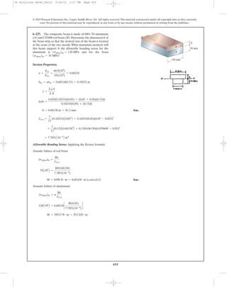
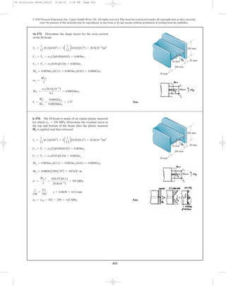
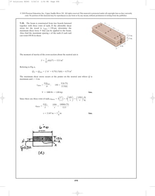
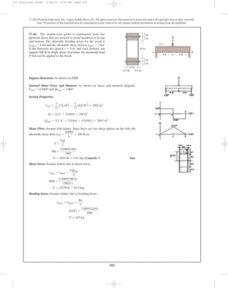
*6–132. The top plate is made of 2014-T6 aluminum and is
used to reinforce a Kevlar 49 plastic beam. Determine the
maximum stress in the aluminum and in the Kevlar if the
beam is subjected to a moment of M = 900 lb # ft.
0.5 in.
6 in.
0.5 in.
0.5 in.
12 in.
M
0.5 in.
06 Solutions 46060_Part2 5/26/10 1:17 PM Page 420](https://image.slidesharecdn.com/ch06-07purebendingtransverseshear-180519192449/85/Ch06-07-pure-bending-amp-transverse-shear-93-320.jpg)
![421
© 2010 Pearson Education, Inc., Upper Saddle River, NJ. All rights reserved.This material is protected under all copyright laws as they currently
exist. No portion of this material may be reproduced, in any form or by any means, without permission in writing from the publisher.
Section Properties:
Maximum Bending Stress: Applying the flexure formula
Assume failure of aluminium
Assume failure of Kevlar 49
Ans.= 16.4 kip # ft (Controls!)
M = 196.62 kip # in
8 =
M(6 - 2.5247)
85.4170
(sallow)k =
Mc
I
M = 1762 kip # in = 146.9 kip # ft
40 = 0.55789 c
M(6 - 2.5247)
85.4170
d
(sallow)al = n
Mc
I
= 85.4170 in4
+
1
12
(6.6947)A0.53
B + 6.6947(0.5)(5.75 - 2.5247)2
+
1
12
(1)A5.53
B + 1(5.5)(3.25 - 2.5247)2
INA =
1
12
(13)A0.53
B + 13(0.5)(2.5247 - 0.25)2
= 2.5247 in.
y =
© yA
©A
=
0.25(13)(0.5) + 2[(3.25)(5.5)(0.5)] + 5.75(6.6947(0.5)
13(0.5) + 2(5.5)(0.5) + 6.6947(0.5)
bk = n bal = 0.55789(12) = 6.6947 in.
n =
Eal
Ek
=
10.6(103
)
19.0(103
)
= 0.55789
•6–133. The top plate made of 2014-T6 aluminum is used
to reinforce a Kevlar 49 plastic beam. If the allowable
bending stress for the aluminum is and
for the Kevlar , determine the maximum
moment M that can be applied to the beam.
(sallow)k = 8 ksi
(sallow)al = 40 ksi
0.5 in.
6 in.
0.5 in.
0.5 in.
12 in.
M
0.5 in.
06 Solutions 46060_Part2 5/26/10 1:17 PM Page 421](https://image.slidesharecdn.com/ch06-07purebendingtransverseshear-180519192449/85/Ch06-07-pure-bending-amp-transverse-shear-94-320.jpg)
![430
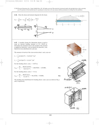
Normal Stress: Curved-beam formula
[1]
[2]
[3]
Denominator of Eq. [1] becomes,
Using Eq. [2],
But,
Then,
Eq. [1] becomes
Using Eq. [2],
Using Eq. [3],
=
Mr
AI
C
LA
y
r + y
dA - y
LA
dA
r + y
S
s =
Mr
AI
CA - ¢A -
LA
y
r + y
dA≤ - y
LA
dA
r + y
S
s =
Mr
AI
(A - rA¿ - yA¿)
s =
Mr
AI
(A - rA¿)
Ar(rA¿ - A) :
A
r
I
1A y dA = 0, as
y
r
: 0
=
A
r LA
¢
y2
1 + y
r
≤dA - A1A y dA -
Ay
r LA
¢
y
1 + y
r
≤ dA
= A
LA
y2
r + y
dA - A1A y dA - Ay
LA
y
r + y
dA
Ar(rA¿ - A) = -A
LA
¢
ry
r + y
+ y - y≤dA - Ay
LA
y
r + y
dA
Ar(rA¿ - A) = Ar¢A -
LA
y
r + y
dA - A≤ = -Ar
LA
y
r + y
dA
= A -
LA
y
r + y
dA
=
LA
a
r - r - y
r + y
+ 1b dA
rA¿ = r
LA
dA
r
=
LA
a
r
r + y
- 1 + 1bdA
r = r + y
s =
M(A - rA¿)
Ar(rA¿ - A)
s =
M(R - r)
Ar(r - R)
where A¿ =
LA
dA
r
and R =
A
1A
dA
r
=
A
A¿
6–143. For the curved beam in Fig. 6–40a, show that when
the radius of curvature approaches infinity, the curved-beam
formula, Eq. 6–24, reduces to the flexure formula, Eq. 6–13.
© 2010 Pearson Education, Inc., Upper Saddle River, NJ. All rights reserved.This material is protected under all copyright laws as they currently
exist. No portion of this material may be reproduced, in any form or by any means, without permission in writing from the publisher.
06 Solutions 46060_Part2 5/26/10 1:17 PM Page 430](https://image.slidesharecdn.com/ch06-07purebendingtransverseshear-180519192449/85/Ch06-07-pure-bending-amp-transverse-shear-103-320.jpg)
![446
© 2010 Pearson Education, Inc., Upper Saddle River, NJ. All rights reserved.This material is protected under all copyright laws as they currently
exist. No portion of this material may be reproduced, in any form or by any means, without permission in writing from the publisher.
Ans.stop = sbottom = 293.5 - 250 = 43.5 MPa
y
250
=
0.115
293.5
; y = 0.09796 m = 98.0 mm
s =
Mp c
I
=
211.25(103
)(0.115)
82.78333(10-6
)
= 293.5 MPa
= 0.000845(250)(106
) = 211.25 kN # m
Mp = 0.003sY (0.215) + 0.002sY (0.1) = 0.000845 sY
C2 = T2 = sY (0.1)(0.02) = 0.002sY
C1 = T1 = sY (0.2)(0.015) = 0.003sY
Ix =
1
12
(0.2)(0.23)3
-
1
12
(0.18)(0.2)3
= 82.78333(10-6
)m4
•6–165. The beam is made of an elastic plastic material for
which Determine the residual stress in the
beam at its top and bottom after the plastic moment is
applied and then released.
Mp
sY = 250 MPa.
200 mm
15 mm
15 mm
20 mm
200 mm
Mp
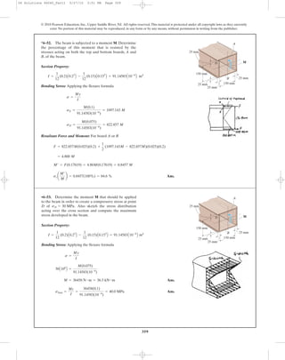
Plastic analysis:
Elastic analysis:
Shape factor:
Ans.=
3h
2
c
4bt(h - t) + t(h - 2t)2
bh3
- (b - t)(h - 2t)3
d
k =
MP
MY
=
[bt(h - t) + t
4 (h - 2t)2
]sY
bh3
- (b - t)(h - 2t)3
6h sY
=
bh3
- (b - t)(h - 2t)3
6h
sY
MY =
sy I
c
=
sYA 1
12 B[bh3
- (b - t)(h - 2t)3
]
h
2
=
1
12
[bh3
- (b - t)(h - 2 t)3
]
I =
1
12
bh3
-
1
12
(b - t)(h - 2t)3
= sYcbt(h - t) +
t
4
(h - 2t)2
d
MP = sY bt(h - t) + sY a
h - 2t
2
b(t)a
h - 2t
2
b
T1 = C1 = sY bt; T2 = C2 = sY a
h - 2t
2
bt
6–166. The wide-flange member is made from an elastic-
plastic material. Determine the shape factor.
t
b
h
t
t
06 Solutions 46060_Part2 5/26/10 1:18 PM Page 446](https://image.slidesharecdn.com/ch06-07purebendingtransverseshear-180519192449/85/Ch06-07-pure-bending-amp-transverse-shear-119-320.jpg)
![459
© 2010 Pearson Education, Inc., Upper Saddle River, NJ. All rights reserved.This material is protected under all copyright laws as they currently
exist. No portion of this material may be reproduced, in any form or by any means, without permission in writing from the publisher.
Maximum Internal Moment: The maximum internal moment occurs at
the mid span as shown on FBD.
Stress–Strain Relationship: Using the stress–strain relationship. the bending stress
can be expressed in terms of y using .
When , and
Resultant Internal Moment: The resultant internal moment M can be evaluated
from the integal .
Equating
Ans.P = 0.100 kip = 100 lb
M = 4.00P(12) = 4.798
= 4.798 kip # in
= 80B
1 + (0.0225)2
y2
2(0.0225)2
tan-1
(0.0225y) -
y
2(0.0225)
R 2
2in.
0
= 80
L
2in
0
y tan-1
(0.0225y) dy
= 2
L
2in
0
yC20 tan
-1
(0.0225y)D(2dy)
M = 2
LA
ysdA
LA
ysdA
smax = 0.8994 ksiy = 2 in.emax = 0.003 in.>in.
= 20 tan-1
(0.0225y)
= 20 tan-1
[15(0.0015y)]
s = 20 tan-1
(15e)
e = 0.0015y
M = 4.00P
*6–184. The beam is made of a polyester that has the
stress–strain curve shown. If the curve can be represented
by the equation where
is in radians, determine the magnitude of the force P that
can be applied to the beam without causing the maximum
strain in its fibers at the critical section to exceed
Pmax = 0.003 in.>in.
tan-1
115P2s = [20 tan-1
115P2] ksi,
8 ft 8 ft
P
2 in.
4 in.
P(in./in.)
Ϯs(ksi)
s ϭ 20 tanϪ1
(15 P)
06 Solutions 46060_Part2 5/26/10 1:18 PM Page 459](https://image.slidesharecdn.com/ch06-07purebendingtransverseshear-180519192449/85/Ch06-07-pure-bending-amp-transverse-shear-132-320.jpg)
![463
© 2010 Pearson Education, Inc., Upper Saddle River, NJ. All rights reserved.This material is protected under all copyright laws as they currently
exist. No portion of this material may be reproduced, in any form or by any means, without permission in writing from the publisher.
Ans.
Note:The centroid of a trapezodial area was used in calculation of moment areas.
= 882.09 kip # in. = 73.5 kip # ft
M = 81(3.6680) + 266(2.1270) + 36(0.5333)
C3 = T3 =
1
2
(0.4)(60)(3) = 36 kip
C2 = T2 =
1
2
(1.2666)(60 + 80)(3) = 266 kip
C1 = T1 =
1
2
(0.3333)(80 + 82)(3) = 81 kip
s - 80
0.03 - 0.025
=
90 - 80
0.05 - 0.025
; s = 82 ksi
•6–189. The bar is made of an aluminum alloy having a
stress–strain diagram that can be approximated by the
straight line segments shown.Assuming that this diagram is
the same for both tension and compression, determine the
moment the bar will support if the maximum strain at the
top and bottom fibers of the beam is Pmax = 0.03.
90
0.050.006 0.025
80
60
4 in. M
3 in.
P(in./in.)
Ϯs(ksi)
Section Properties:
Bending Stress: Applying the flexure formula
Resultant Force:
Ans.= 5883 N = 5.88 kN
FR =
1
2
(1.0815 + 1.6234)A106
B (0.015)(0.29)
sA =
650(0.044933)
17.99037(10-6
)
= 1.6234 MPa
sB =
650(0.044933 - 0.015)
17.99037(10-6
)
= 1.0815 MPa
s =
My
I
= 17.99037 A10-6
B m4
+
1
12
(0.04)A0.1253
B + 0.04(0.125)(0.0775 - 0.044933)2
INA =
1
12
(0.29)A0.0153
B + 0.29(0.015)(0.044933 - 0.0075)2
= 0.044933 m
y =
0.0075(0.29)(0.015) + 2[0.0775(0.125)(0.02)]
0.29(0.015) + 2(0.125)(0.02)
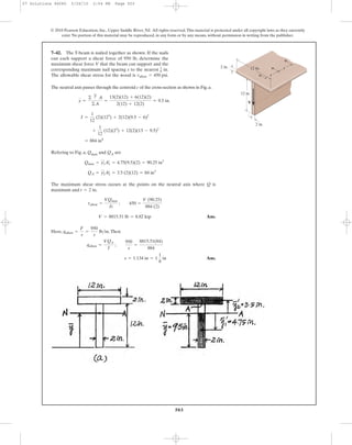
6–190. The beam is made from three boards nailed together
as shown. If the moment acting on the cross section is
determine the resultant force the bending
stress produces on the top board.
M = 650 N # m,
M ϭ 650 Nиm
250 mm
15 mm
125 mm 20 mm
20 mm
06 Solutions 46060_Part2 5/26/10 1:18 PM Page 463](https://image.slidesharecdn.com/ch06-07purebendingtransverseshear-180519192449/85/Ch06-07-pure-bending-amp-transverse-shear-136-320.jpg)
![464
© 2010 Pearson Education, Inc., Upper Saddle River, NJ. All rights reserved.This material is protected under all copyright laws as they currently
exist. No portion of this material may be reproduced, in any form or by any means, without permission in writing from the publisher.
Section Properties:
Maximum Bending Stress: Applying the flexure formula
Ans.
Ans.(smax)c =
650(0.044933)
17.99037(10-6
)
= 1.62 MPa (C)
(smax)t =
650(0.14 - 0.044933)
17.99037(10-6
)
= 3.43 MPa (T)
s =
My
I
= 17.99037A10-6
B m4
+
1
12
(0.04)A0.1253
B + 0.04(0.125)(0.0775 - 0.044933)2
INA =
1
12
(0.29)A0.0153
B + 0.29(0.015)(0.044933 - 0.0075)2
= 0.044933 m
y =
0.0075(0.29)(0.015) + 2[0.0775(0.125)(0.02)]
0.29(0.015) + 2(0.125)(0.02)
6–191. The beam is made from three boards nailed together
as shown. Determine the maximum tensile and compressive
stresses in the beam.
M ϭ 650 Nиm
250 mm
15 mm
125 mm 20 mm
20 mm
06 Solutions 46060_Part2 5/26/10 1:18 PM Page 464](https://image.slidesharecdn.com/ch06-07purebendingtransverseshear-180519192449/85/Ch06-07-pure-bending-amp-transverse-shear-137-320.jpg)
![467
© 2010 Pearson Education, Inc., Upper Saddle River, NJ. All rights reserved.This material is protected under all copyright laws as they currently
exist. No portion of this material may be reproduced, in any form or by any means, without permission in writing from the publisher.
Maximum Bending Stress: The moment of inertia about y axis must be
determined first in order to use Flexure Formula
Thus,
Ans.
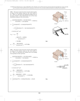
Maximum Bending Stress: Using integration
Ans.smax = 0.410 N>mm2
= 0.410 MPa
125A103
B =
smax
5
(1.5238) A106
B
125A103
B =
smax
5
B -
3
2
y2
(100 - y)
3
2 -
8
15
y(100 - y)
5
2 -
16
105
(100 - y)
7
2 R 2
100mm
0
M =
smax
5 L
100mm
0
y2
2100 - y dy
dM = 2[y(s dA)] = 2byc a
smax
100
byd(2z dy)r
smax =
Mc
I
=
125(0.1)
30.4762(10-6
)
= 0.410 MPa
= 30.4762 A10-6
B mm4
= 30.4762 A10-6
B m4
= 20B -
3
2
y2
(100 - y)
3
2 -
8
15
y(100 - y)
5
2 -
16
105
(100 - y)
7
2 R 2
100mm
0
= 20
L
100mm
0
y2
2100 - y dy
= 2
L
100mm
0
y2
(2z) dy
I =
LA
y2
dA
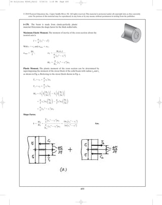
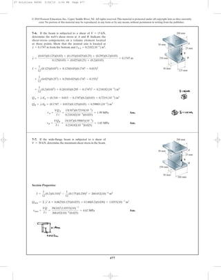
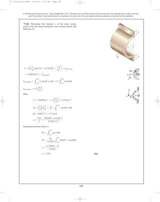
6–195. A shaft is made of a polymer having a parabolic
cross section. If it resists an internal moment of
, determine the maximum bending stress
developed in the material (a) using the flexure formula and
(b) using integration. Sketch a three-dimensional view of
the stress distribution acting over the cross-sectional area.
Hint: The moment of inertia is determined using Eq.A–3 of
Appendix A.
M = 125 N # m
y
z
x
M ϭ 125 N·m
50 mm
100 mm
50 mm
y ϭ 100 – z2
/25
06 Solutions 46060_Part2 5/26/10 1:18 PM Page 467](https://image.slidesharecdn.com/ch06-07purebendingtransverseshear-180519192449/85/Ch06-07-pure-bending-amp-transverse-shear-140-320.jpg)
![472
© 2010 Pearson Education, Inc., Upper Saddle River, NJ. All rights reserved.This material is protected under all copyright laws as they currently
exist. No portion of this material may be reproduced, in any form or by any means, without permission in writing from the publisher.
The moment of inertia of the cross-section about the neutral axis is
From Fig. a,
Applying the shear formula,
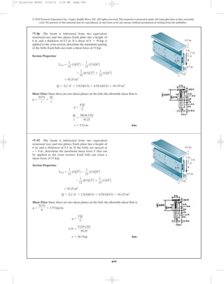
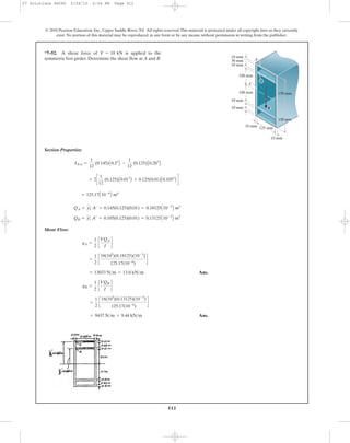
Ans.
The shear stress component at A is represented by the volume element shown in
Fig. b.
= 2.559(106
) Pa = 2.56 MPa
tA =
VQA
It
=
20(103
)[0.64(10-3
)]
0.2501(10-3
)(0.02)
QA = y¿A¿ = 0.16 (0.02)(0.2) = 0.64(10-3
) m3
I =
1
12
(0.2)(0.343
) -
1
12
(0.18)(0.33
) = 0.2501(10-3
) m4
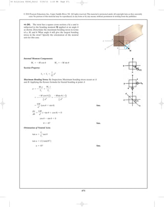
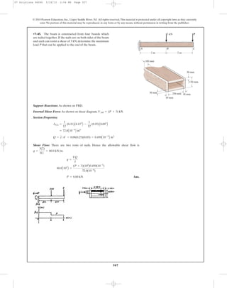
•7–1. If the wide-flange beam is subjected to a shear of
determine the shear stress on the web at A.
Indicate the shear-stress components on a volume element
located at this point.
V = 20 kN,
A
B
V
20 mm
20 mm
20 mm
300 mm
200 mm
200 mm
07 Solutions 46060 5/26/10 2:04 PM Page 472](https://image.slidesharecdn.com/ch06-07purebendingtransverseshear-180519192449/85/Ch06-07-pure-bending-amp-transverse-shear-145-320.jpg)
![473
© 2010 Pearson Education, Inc., Upper Saddle River, NJ. All rights reserved.This material is protected under all copyright laws as they currently
exist. No portion of this material may be reproduced, in any form or by any means, without permission in writing from the publisher.
The moment of inertia of the cross-section about the neutral axis is
From Fig. a.
The maximum shear stress occurs at the points along neutral axis since Q is
maximum and thicknest t is the smallest.
Ans.= 3.459(106
) Pa = 3.46 MPa
tmax =
VQmax
It
=
20(103
) [0.865(10-3
)]
0.2501(10-3
) (0.02)
Qmax = ©y¿A¿ = 0.16 (0.02)(0.2) + 0.075 (0.15)(0.02) = 0.865(10-3
) m3
I =
1
12
(0.2)(0.343
) -
1
12
(0.18)(0.33
) = 0.2501(10-3
) m4
7–2. If the wide-flange beam is subjected to a shear of
determine the maximum shear stress in the beam.V = 20 kN,
A
B
V
20 mm
20 mm
20 mm
300 mm
200 mm
200 mm
07 Solutions 46060 5/26/10 2:04 PM Page 473](https://image.slidesharecdn.com/ch06-07purebendingtransverseshear-180519192449/85/Ch06-07-pure-bending-amp-transverse-shear-146-320.jpg)
![478
© 2010 Pearson Education, Inc., Upper Saddle River, NJ. All rights reserved.This material is protected under all copyright laws as they currently
exist. No portion of this material may be reproduced, in any form or by any means, without permission in writing from the publisher.
Ans.Vw = 30 - 2(1.457) = 27.1 kN
Vf = 1.457 kN
= 11.1669(10)6
[ 0.024025y -
1
2
y3
]
0.155
0.125
Vf =
L
tf dA = 55.8343(10)6
L
0.155
0.125
(0.024025 - y2
)(0.2 dy)
tf =
30(10)3
(0.1)(0.024025 - y2
)
268.652(10)-6
(0.2)
Q = a
0.155 + y
2
b(0.155 - y)(0.2) = 0.1(0.024025 - y2
)
I =
1
12
(0.2)(0.310)3
-
1
12
(0.175)(0.250)3
= 268.652(10)-6
m4
*7–8. If the wide-flange beam is subjected to a shear of
determine the shear force resisted by the web
of the beam.
V = 30 kN,
A
B
V
30 mm
25 mm
30 mm
250 mm
200 mm
200 mm
Ans.V = 32132 lb = 32.1 kip
8(103
) = -
V(3.3611)
6.75(2)(1)
tmax = tallow =
VQmax
I t
Qmax = ©y¿A¿ = 2 (0.91665)(1.8333)(1) = 3.3611 in3
+ 2 a
1
12
b(1)(23
) + 2(1)(2)(2 - 1.1667)2
= 6.75 in4
I =
1
12
(5)(13
) + 5 (1)(1.1667 - 0.5)2
y =
(0.5)(1)(5) + 2 [(2)(1)(2)]
1 (5) + 2(1)(2)
= 1.1667 in.
•7–9. Determine the largest shear force V that the member
can sustain if the allowable shear stress is tallow = 8 ksi.
V
3 in. 1 in.
1 in.
1 in.
3 in.
07 Solutions 46060 5/26/10 2:04 PM Page 478](https://image.slidesharecdn.com/ch06-07purebendingtransverseshear-180519192449/85/Ch06-07-pure-bending-amp-transverse-shear-151-320.jpg)
![479
© 2010 Pearson Education, Inc., Upper Saddle River, NJ. All rights reserved.This material is protected under all copyright laws as they currently
exist. No portion of this material may be reproduced, in any form or by any means, without permission in writing from the publisher.
Ans.tmax =
VQmax
I t
=
18(3.3611)
6.75(2)(1)
= 4.48 ksi
Qmax = ©y¿A¿ = 2(0.91665)(1.8333)(1) = 3.3611 in3
+ 2 a
1
12
b(1)(23
) + 2(1)(2)(2 - 1.1667) = 6.75 in4
I =
1
12
(5)(13
) + 5(1)(1.1667 - 0.5)2
y =
(0.5)(1)(5) + 2 [(2)(1)(2)]
1 (5) + 2(1)(2)
= 1.1667 in.
7–10. If the applied shear force determine the
maximum shear stress in the member.
V = 18 kip,
V
3 in. 1 in.
1 in.
1 in.
3 in.
Ans.V = 100 kN
7(106
) =
V[(0.075)(0.1)(0.05) + 2(0.05)(0.1)(0.05)]
125(10-6
)(0.1)
tallow =
VQmax
It
I =
1
12
(0.2)(0.2)3
-
1
12
(0.1)(0.1)3
= 125(10-6
) m4
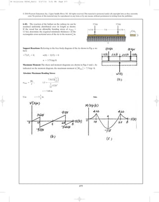
7–11. The wood beam has an allowable shear stress of
Determine the maximum shear force V that
can be applied to the cross section.
tallow = 7 MPa.
50 mm
50 mm
200 mm
100 mm
50 mm
V
50 mm
07 Solutions 46060 5/26/10 2:04 PM Page 479](https://image.slidesharecdn.com/ch06-07purebendingtransverseshear-180519192449/85/Ch06-07-pure-bending-amp-transverse-shear-152-320.jpg)
![482
© 2010 Pearson Education, Inc., Upper Saddle River, NJ. All rights reserved.This material is protected under all copyright laws as they currently
exist. No portion of this material may be reproduced, in any form or by any means, without permission in writing from the publisher.
The maximum shear stress occur when
Ans.The faector =
tmax
tavg
=
4V
3 pc2
V
pc2
=
4
3
tavg =
V
A
=
V
p c2
tmax =
4V
3 pc2
y = 0
t =
VQ
I t
=
V[2
3 (c2
- y2
)
3
2]
(p
4 c4
)(22c2
- y2
)
=
4V
3pc4
[c2
- y2
)
Q =
L
x
y
2y2c2
- y2
dy = -
2
3
(c2
- y2
)
3
2 |
x
y =
2
3
(c2
- y2
)
2
3
dQ = ydA = 2y2c2
- y2
dy
dA = 2xdy = 22c2
- y2
dy
t = 2x = 22c2
- y2
x = 2c2
- y2
; I =
p
4
c4
7–15. Plot the shear-stress distribution over the cross
section of a rod that has a radius c. By what factor is the
maximum shear stress greater than the average shear stress
acting over the cross section?
c
V
y
07 Solutions 46060 5/26/10 2:04 PM Page 482](https://image.slidesharecdn.com/ch06-07purebendingtransverseshear-180519192449/85/Ch06-07-pure-bending-amp-transverse-shear-155-320.jpg)
![484
© 2010 Pearson Education, Inc., Upper Saddle River, NJ. All rights reserved.This material is protected under all copyright laws as they currently
exist. No portion of this material may be reproduced, in any form or by any means, without permission in writing from the publisher.
The moment of inertia of the cross-section about the neutral axis is
From Fig. a,
The maximum shear stress occurs at the points along the neutral axis since Q is
maximum and thickness is the smallest.
Ans.= 37.36(106
) Pa = 37.4 MPa
tmax =
VQmax
It
=
600(103
)[1.09125(10-3
)]
0.175275(10-3
) (0.1)
t = 0.1 m
= 1.09125(10-3
) m3
Qmax = ©y¿A¿ = 0.09(0.03)(0.3) + 0.0375(0.075)(0.1)
I =
1
12
(0.3)(0.213
) -
1
12
(0.2)(0.153
) = 0.175275(10-3
) m4
•7–17. Determine the maximum shear stress in the strut if
it is subjected to a shear force of V = 600 kN.
V
150 mm
30 mm
100 mm
100 mm
100 mm
30 mm
07 Solutions 46060 5/26/10 2:04 PM Page 484](https://image.slidesharecdn.com/ch06-07purebendingtransverseshear-180519192449/85/Ch06-07-pure-bending-amp-transverse-shear-157-320.jpg)

![486
© 2010 Pearson Education, Inc., Upper Saddle River, NJ. All rights reserved.This material is protected under all copyright laws as they currently
exist. No portion of this material may be reproduced, in any form or by any means, without permission in writing from the publisher.
The moment of inertia of the cross-section about the neutral axis is
For , Fig. a, Q as a function of y is
For , Fig. b, Q as a function of y is0 … y 6 0.075 m
Q = y¿A¿ =
1
2
(0.105 + y) (0.105 - y)(0.3) = 1.65375(10-3
) - 0.15y2
0.075 m 6 y … 0.105 m
I =
1
12
(0.3)(0.213
) -
1
12
(0.2)(0.153
) = 0.175275(10-3
) m4
7–19. Plot the intensity of the shear stress distributed over
the cross section of the strut if it is subjected to a shear force
of V = 600 kN.
V
150 mm
30 mm
100 mm
100 mm
100 mm
30 mm
Q = ©y¿A¿ = 0.09 (0.03)(0.3) +
1
2
(0.075 + y)(0.075 - y)(0.1) = 1.09125(10-3
) - 0.05 y2
For , .Thus,
At and ,
For , .Thus,
At and ,
The plot shear stress distribution over the cross-section is shown in Fig. c.
t|y=0 = 37.4 MPa ty=0.075 m = 27.7 MPa
y = 0.075 my = 0
t =
VQ
It
=
600(103
) [1.09125(10-3
) - 0.05y2
]
0.175275(10-3
) (0.1)
= (37.3556 - 1711.60 y2
) MPa
t = 0.1 m0 … y 6 0.075 m
t|y=0.015 m = 9.24 MPa ty=0.105 m = 0
y = 0.105 my = 0.075 m
t =
VQ
It
=
600(103
) C1.65375(10-3
) - 0.15y2
D
0.175275(10-3
) (0.3)
= (18.8703 - 1711.60y2
) MPa
t = 0.3 m0.075 m 6 y … 0.105 m
07 Solutions 46060 5/26/10 2:04 PM Page 486](https://image.slidesharecdn.com/ch06-07purebendingtransverseshear-180519192449/85/Ch06-07-pure-bending-amp-transverse-shear-159-320.jpg)
![510510
© 2010 Pearson Education, Inc., Upper Saddle River, NJ. All rights reserved.This material is protected under all copyright laws as they currently
exist. No portion of this material may be reproduced, in any form or by any means, without permission in writing from the publisher.
The moment of inertia of the cross-section about the neutral axis is
Refering to Fig. a Fig. b,
Due to symmety, the shear flow at points A and , Fig. a, and at points B and ,
Fig. b, are the same.Thus
Ans.
Ans.= 462.46(103
) N>m = 462 kN>m
qB =
1
2
a
VQB
I
b =
1
2
c
300(103
) C0.751(10-3
)D
0.24359(10-3
)
s
= 228.15(103
) N>m = 228 kN>m
qA =
1
2
a
VQA
I
b =
1
2
c
300(103
) C0.3705(10-3
)D
0.24359(10-3
)
s
B¿A¿
QB = 2yœ
zA2
œ
+ y3
œ
A3
œ
= 2[0.1(0.2)(0.01)] + 0.195(0.01)(0.18) = 0.751(10-3
) m3
QA = y1
œ
A1
œ
= 0.195 (0.01)(0.19) = 0.3705 (10-3
) m3
I =
1
12
(0.2)(0.43
) -
1
12
(0.18)(0.383
) = 0.24359(10-3
) m4
7–50. A shear force of is applied to the box
girder. Determine the shear flow at points A and B.
V = 300 kN
100 mm
90 mm90 mm
200 mm
200 mm
180 mm
190 mm
10 mm
10 mm
V
A D
C
B
07 Solutions 46060 5/26/10 2:04 PM Page 510](https://image.slidesharecdn.com/ch06-07purebendingtransverseshear-180519192449/85/Ch06-07-pure-bending-amp-transverse-shear-183-320.jpg)
![514
© 2010 Pearson Education, Inc., Upper Saddle River, NJ. All rights reserved.This material is protected under all copyright laws as they currently
exist. No portion of this material may be reproduced, in any form or by any means, without permission in writing from the publisher.
Ans.
Ans.qB =
VQB
I
=
150(8.1818)(10-6
)
0.98197(10-6
)
= 1.25 kN>m
qA =
VQA
I
=
150(9.0909)(10-6
)
0.98197(10-6
)
= 1.39 kN>m
QB = yB¿A¿ = 0.027272(0.03)(0.01) = 8.1818(10-6
) m3
QA = yA¿A¿ = 0.022727(0.04)(0.01) = 9.0909(10-6
) m3
yA¿ = 0.027727 - 0.005 = 0.022727 m
yB¿ = 0.055 - 0.027727 = 0.027272 m
+
1
12
(0.04)(0.01)3
+ 0.04(0.01)(0.055 - 0.027727)2
= 0.98197(10-6
) m4
+ 2c
1
12
(0.01)(0.06)3
+ 0.01(0.06)(0.03 - 0.027727)2
d
I = 2c
1
12
(0.03)(0.01)3
+ 0.03(0.01)(0.027727 - 0.005)2
d
y =
2[0.005(0.03)(0.01)] + 2[0.03(0.06)(0.01)] + 0.055(0.04)(0.01)
2(0.03)(0.01) + 2(0.06)(0.01) + 0.04(0.01)
= 0.027727 m
7–54. The aluminum strut is 10 mm thick and has the cross
section shown. If it is subjected to a shear of, ,
determine the shear flow at points A and B.
V = 150 N
30 mm
40 mm
30 mm
V
A
B40 mm
10 mm
10 mm
10 mm10 mm
= 0.98197(10-6
) m4
+
1
12
(0.04)(0.01)3
+ 0.04(0.01)(0.055 - 0.027727)2
+ 2c
1
12
(0.01)(0.06)3
+ 0.01(0.06)(0.03 - 0.027727)2
d
I = 2c
1
12
(0.03)(0.01)3
+ 0.03(0.01)(0.027727 - 0.005)2
d
= 0.027727 m
y =
2[0.005(0.03)(0.01)] + 2[0.03(0.06)(0.01)] + 0.055(0.04)(0.01)
2(0.03)(0.01) + 2(0.06)(0.01) + 0.04(0.01)
7–55. The aluminum strut is 10 mm thick and has the cross
section shown. If it is subjected to a shear of ,
determine the maximum shear flow in the strut.
V = 150 N
30 mm
40 mm
30 mm
V
A
B40 mm
10 mm
10 mm
10 mm10 mm
Qmax = (0.055 - 0.027727)(0.04)(0.01) + 2[(0.06 - 0.027727)(0.01)]a
0.06 - 0.0277
2
b
Ans.qmax =
1
2
a
VQmax
I
b =
1
2
a
150(21.3(10-6
))
0.98197(10-6
)
b = 1.63 kN>m
= 21.3(10-6
) m3
07 Solutions 46060 5/26/10 2:04 PM Page 514](https://image.slidesharecdn.com/ch06-07purebendingtransverseshear-180519192449/85/Ch06-07-pure-bending-amp-transverse-shear-187-320.jpg)
![515
© 2010 Pearson Education, Inc., Upper Saddle River, NJ. All rights reserved.This material is protected under all copyright laws as they currently
exist. No portion of this material may be reproduced, in any form or by any means, without permission in writing from the publisher.
y =
©yA
©A
=
0.25(11)(0.5) + 2[4.5(8)(0.5)] + 6.25(10)(0.5)
11(0.5) + 2(8)(0.5) + 10(0.5)
= 3.70946 in.
*7–56. The beam is subjected to a shear force of
. Determine the shear flow at points A and B.V = 5 kip
A
V
0.5 in.
0.5 in.
5 in.
5 in.
0.5 in.
2 in. 0.5 in.
8 in.
B
A
C
D
I =
1
12
(11)(0.53
) + 11(0.5)(3.70946 - 0.25)2
+ 2c
1
12
(0.5)(83
) + 0.5(8)(4.5 - 3.70946)2
d
Ans.
Ans.qB =
1
2
a
VQB
I
b =
1
2
a
5(103
)(12.7027)
145.98
b = 218 lb>in.
qA =
1
2
a
VQA
I
b =
1
2
a
5(103
)(19.02703)
145.98
b = 326 lb>in.
QB = yB
œ
A¿ = 2.54054(10)(0.5) = 12.7027 in3
QA = yA
œ
A¿ = 3.45946(11)(0.5) = 19.02703 in3
yB
œ
= 6.25 - 3.70946 = 2.54054 in.
yA
œ
= 3.70946 - 0.25 = 3.45946 in.
= 145.98 in4
+
1
12
(10)(0.53
) + 10(0.5)(6.25 - 3.70946)2
Ans.= 414 lb>in.
qmax =
1
2
a
VQmax
I
b =
1
2
a
5(103
)(24.177)
145.98
b
= 24.177 in3
Qmax = 3.4594 (11)(0.5) + 2[(1.6047)(0.5)(3.7094 - 0.5)]
= 145.98 in4
+
1
12
(10)(0.53
) + 10(0.5)(2.54052
)
I =
1
12
(11)(0.53
) + 11(0.5)(3.45952
) + 2c
1
12
(0.5)(83
) + 0.5(8)(0.79052
)d
y =
©yA
©A
=
0.25(11)(0.5) + 2[4.5(8)(0.5)] + 6.25(10)(0.5)
11(0.5) + 2(8)(0.5) + 10(0.5)
= 3.70946 in.
•7–57. The beam is constructed from four plates and is
subjected to a shear force of . Determine the
maximum shear flow in the cross section.
V = 5 kip
A
V
0.5 in.
0.5 in.
5 in.
5 in.
0.5 in.
2 in. 0.5 in.
8 in.
B
A
C
D
07 Solutions 46060 5/26/10 2:04 PM Page 515](https://image.slidesharecdn.com/ch06-07purebendingtransverseshear-180519192449/85/Ch06-07-pure-bending-amp-transverse-shear-188-320.jpg)
![516
© 2010 Pearson Education, Inc., Upper Saddle River, NJ. All rights reserved.This material is protected under all copyright laws as they currently
exist. No portion of this material may be reproduced, in any form or by any means, without permission in writing from the publisher.
Ans.qA =
75(103
)(0.3450)(10-3
)
0.12025(10-3
)
= 215 kN>m
q =
VQ
I
QA = yA
œ
A¿ = 0.0575(0.2)(0.03) = 0.3450(10-3
) m3
+ 2c
1
12
(0.03)(0.23
) + 0.03(0.2)(0.13 - 0.0725)2
d = 0.12025(10-3
) m4
I =
1
12
(0.4)(0.033
) + 0.4(0.03)(0.0725 - 0.015)2
y =
©yA
©A
=
0.015(0.4)(0.03) + 2[0.13(0.2)(0.03)]
0.4(0.03) + 2(0.2)(0.03)
= 0.0725 m
7–58. The channel is subjected to a shear of .
Determine the shear flow developed at point A.
V = 75 kN
200 mm
30 mm
30 mm
V ϭ 75 kN
30 mm
400 mm
A
Ans.qmax =
75(103
)(0.37209)(10-3
)
0.12025(10-3
)
= 232 kN>m
Qmax = y¿A¿ = 0.07875(0.1575)(0.03) = 0.37209(10-3
) m3
= 0.12025(10-3
) m4
+ 2c
1
12
(0.03)(0.23
) + 0.03(0.2)(0.13 - 0.0725)2
d
I =
1
12
(0.4)(0.033
) + 0.4(0.03)(0.0725 - 0.015)2
= 0.0725 m
y =
©yA
©A
=
0.015(0.4)(0.03) + 2[0.13(0.2)(0.03)]
0.4(0.03) + 2(0.2)(0.03)
7–59. The channel is subjected to a shear of .
Determine the maximum shear flow in the channel.
V = 75 kN
200 mm
30 mm
30 mm
V ϭ 75 kN
30 mm
400 mm
A
07 Solutions 46060 5/26/10 2:04 PM Page 516](https://image.slidesharecdn.com/ch06-07purebendingtransverseshear-180519192449/85/Ch06-07-pure-bending-amp-transverse-shear-189-320.jpg)
![517
© 2010 Pearson Education, Inc., Upper Saddle River, NJ. All rights reserved.This material is protected under all copyright laws as they currently
exist. No portion of this material may be reproduced, in any form or by any means, without permission in writing from the publisher.
Section Properties:
Shear Flow:
Ans.
At Ans.y = 0, q = qmax = 424 lb>in.
= {424 - 136y2
} lb>in.
=
2(103
)(0.55243 - 0.17678y2
)
2.604167
q =
VQ
I
= 0.55243 - 0.17678y2
Q = y¿A¿ = [0.25(3.53553) + 0.5y]a2.5 -
y
sin 45°
b(0.25)
INA = 2c
1
12
(0.35355)A3.535533
B d = 2.604167 in4
h = 5 cos 45° = 3.53553 in.
b =
0.25
sin 45°
= 0.35355 in.
*7–60. The angle is subjected to a shear of .
Sketch the distribution of shear flow along the leg AB.
Indicate numerical values at all peaks.
V = 2 kip
45Њ 45Њ
V
A
B
5 in.
5 in.
0.25 in.
07 Solutions 46060 5/26/10 2:04 PM Page 517](https://image.slidesharecdn.com/ch06-07purebendingtransverseshear-180519192449/85/Ch06-07-pure-bending-amp-transverse-shear-190-320.jpg)
![519
© 2010 Pearson Education, Inc., Upper Saddle River, NJ. All rights reserved.This material is protected under all copyright laws as they currently
exist. No portion of this material may be reproduced, in any form or by any means, without permission in writing from the publisher.
Here
Therefore
Here
Ans.
occurs at ; therefore
; therefore
QEDtmax =
2V
A
A = 2pRt
tmax =
V
pR t
y = 0tmax
t =
V
pR2
t
2R2
- y2
cos u =
2R2
- y2
R
t =
VQ
I t
=
V(2R2
t cos u)
pR3
t(2t)
=
V cosu
pR t
=
R3
t
2
[u -
sin 2u
2
] Η
2p
0
=
R3
t
2
[2p - 0] = pR3
t
I =
L
2p
0
R3
t sin2
u du = R3
t
L
2p
0
(1 - cos 2u)
2
du
dI = y2
dA = y2
R t du = R3
t sin2
u du
= R2
t [-cos (p - u) - (-cosu)] = 2R2
t cosu
Q =
L
p-u
u
R2
t sin u du = R2
t(-cosu) |
p- u
u
dQ = R2
t sin u du
y = R sin u
dQ = y dA = yR t du
dA = R t du
7–62. Determine the shear-stress variation over the cross
section of the thin-walled tube as a function of elevation y and
show that , where Hint: Choose a
differential area element . Using
formulate Q for a circular section from to and show
that where cos u = 2R2
- y2
>R.Q = 2R2
t cos u,
(p - u)u
dQ = ydA,dA = Rt du
A = 2prt.tmax = 2V>A
t
y
du
ds
R
u
07 Solutions 46060 5/26/10 2:04 PM Page 519](https://image.slidesharecdn.com/ch06-07purebendingtransverseshear-180519192449/85/Ch06-07-pure-bending-amp-transverse-shear-192-320.jpg)
![526
© 2010 Pearson Education, Inc., Upper Saddle River, NJ. All rights reserved.This material is protected under all copyright laws as they currently
exist. No portion of this material may be reproduced, in any form or by any means, without permission in writing from the publisher.
Summing moments about A.
(1)
From Eq, (1).
Ans.e =
t
12I
(6h1 h2
b + 3h2
b2
- 8h1
3
b) =
b(6h1 h2
+ 3h2
b - 8h1
3
)
2h3
+ 6bh2
- (h - 2h1)3
I =
t
12
(2h3
+ 6bh2
- (h - 2h1)3
)
Pe =
Pt
2I
[h1 h2
b - h1
2
hb +
h2
b2
2
+ hh1
2
b -
4
3
h1
3
b]
F =
L
q2 dx =
Pt
2I L
b
0
[h1 (h - h1) + hx]dx =
Pt
2I
ah1 hb - h1
2
b +
hb2
2
b
q2 =
VQ2
I
=
Pt
2I
(h1 (h - h1) + hx)
Q2 = ©y¿A¿ =
1
2
(h - h1)h1 t +
h
2
(x)(t) =
1
2
t[h1 (h - h1) + hx]
V =
L
q1 dy =
Pt
2I L
h1
0
(hy - 2h1 y + y2
)dy =
Pt
2I
c
hh1
2
2
-
2
3
h1
3
d
q1 =
VQ
I
=
Pt(hy - 2h1 y + y2
)
2I
Q1 = y¿A¿ =
1
2
(h - 2h1 + y)yt =
t(hy - 2h1 y + y2
)
2
=
th3
6
+
bth2
2
-
t(h - 2h1)3
12
I =
1
12
(t)(h3
) + 2b(t)a
h
2
b
2
+
1
12
(t)[h3
- (h - 2h1)3
]
Pe = F(h) + 2V(b)
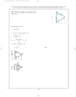
•7–69. Determine the location e of the shear center,
point O, for the thin-walled member having the cross
section shown. The member segments have the same
thickness t.
h
b
e
O
h1
h1
07 Solutions 46060 5/26/10 2:04 PM Page 526](https://image.slidesharecdn.com/ch06-07purebendingtransverseshear-180519192449/85/Ch06-07-pure-bending-amp-transverse-shear-199-320.jpg)


![01 01 chapgere[1]](https://cdn.slidesharecdn.com/ss_thumbnails/01-01chapgere1-130611230425-phpapp02-thumbnail.jpg?width=640&height=640&fit=bounds)


