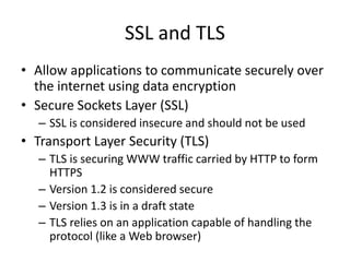
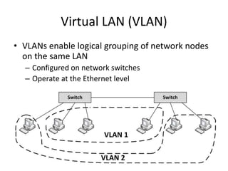
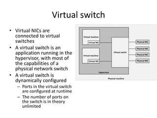
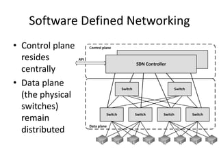
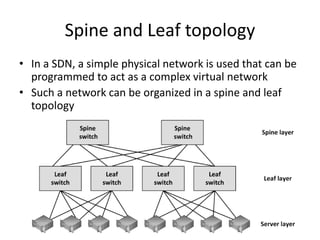
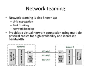
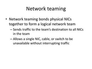
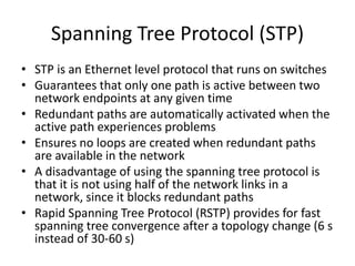
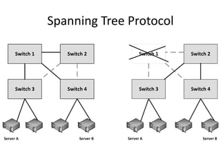
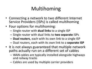
IT Infrastructure Architecture
Networking – Part 2
(chapter 8)
Infrastructure Building Blocks
and Concepts
Presentation layer
Presentation layer
• This layer takes the data provided by the
application layer and converts it into a
standard format that the other layers can
understand
• Many protocols are implemented in the
presentation layer
– SSL and TLS are the most important ones
SSL and TLS
• Allow applications to communicate securely over
the internet using data encryption
• Secure Sockets Layer (SSL)
– SSL is considered insecure and should not be used
• Transport Layer Security (TLS)
– TLS is securing WWW traffic carried by HTTP to form
HTTPS
– Version 1.2 is considered secure
– Version 1.3 is in a draft state
– TLS relies on an application capable of handling the
protocol (like a Web browser)
Application layer
Application layer
• This layer interacts with the operating system
or application
• Examples:
– HTTP
– FTP
– SMTP and POP3 (e-mail)
– CIFS Windows file sharing
Application layer
• This layer also contains the relatively simple
infrastructure services
• Examples:
– BOOTP
– DHCP
– DNS
– NTP
• These infrastructure services are used by the
infrastructure itself
– Not necessarily used by upper layer applications
• If infrastructure services fail, usually the entire
infrastructure fails!
BOOTP and DHCP
• BOOTP automatically assigns IP addresses to hosts
– Uses a centralized BOOTP server
– BOOTP requires manual configuration for each host in the network
• DHCP is an extension to BOOTP
– It superseded BOOTP because it has more options
• DHCP dynamically assigns network related parameters to hosts:
– IP addresses
– Subnet masks
– Default gateway to be used for routing
– DNS server to be used
• A DHCP assigned IP address has a limited life span
– Typically a few hours
– This is called a lease
DNS
• For example,
www.sjaaklaan.com is
translated to 217.149.139.184
• This IP address is used by the
browser to connect to the web
server
• DNS distributes the
responsibility of mapping
domain names to IP addresses
by designating authoritative
name servers for each domain
• DNS is a distributed database that links IP addresses with
domain names
• Translates domain names, meaningful to humans, into IP
addresses
DNSSEC
• DNS has a number of security issues
– DNS was not designed with security in mind
– Updates to DNS records are done in non-encrypted
clear text
– Authorization is based on IP addresses only
• DNSSEC is a set of extensions to DNS
– Provides origin authentication of DNS data
– Provides data integrity
• DNSSEC is not in wide spread use today
– All DNS servers must implement DNSSEC in order to
make full use of all benefits
IPAM systems
• IP address management (IPAM) systems are
appliances that can be used to plan, track, and
manage IP addresses in a network
• IPAM systems integrate DNS, DHCP, and IP
address administration in one high available
redundant set of appliances
Network Time Protocol (NTP)
• NTP ensures all infrastructure components use the
same time in their real-time clocks
• Particularly important for:
– Log file analysis
– Clustering software
– Kerberos authentication
• NTP can maintain time:
– To within 10 milliseconds over the internet
– Accurate to 0.2 milliseconds or better in LANs
• When the time in an operating system is incorrect,
the NTP client in the operating system changes the
operating system clock
Network Time Protocol (NTP)
• NTP servers can be implemented as:
– Software on operating systems, routers, and switches
– Dedicated hardware appliances – often using some
external signal like long wave radio clocks or GPS clocks
– NTP time synchronization services on the internet
• NTP provides time in Coordinated Universal Time (UTC,
previously known as GMT)
• The translation to the local time zone, including the
switch to and from daylight saving time, is done at the
operating system level, not in NTP clocks
Network Time Protocol (NTP)
• NTP operates within a
hierarchy
• Each level in the
hierarchy is assigned a
number called the
stratum
• The stratum defines its
distance from the
reference clock
Network virtualization
Virtual LAN (VLAN)
• VLANs enable logical grouping of network nodes
on the same LAN
– Configured on network switches
– Operate at the Ethernet level
Virtual LAN (VLAN)
• VLANs:
– Allow segmenting a network at the data link layer
– Allow end stations to be grouped together even if
they are not physically connected to the same switch
– Can adapt to changes in network requirements and
allow simplified administration
– Enhance security by preventing traffic in one VLAN
from being seen by hosts in a different VLAN
• For VLANs to communicate with each other a
router is needed
VXLAN
• Virtual Extensible LAN (VXLAN) is an
encapsulation protocol
• Can be used to create a logical switched layer 2
network across routed layer 3 networks
• Only servers within the same logical network
can communicate with each other
• VXLANs are heavily used in multi-tenant cloud
environments
Virtual NICs
• Virtual machines are only aware of virtual Network
Interface Controllers (NICs) provided to them
• Virtual machines running on physical machines share
physical NICs
• Communications between virtual machines on the
same physical machine are routed directly in memory
space by the hypervisor, without using the physical NIC
• The hypervisor routes Ethernet packages from the
virtual NIC on the virtual machine to the physical NIC on
the physical machine
Virtual switch
• Virtual NICs are
connected to virtual
switches
• A virtual switch is an
application running in the
hypervisor, with most of
the capabilities of a
physical network switch
• A virtual switch is
dynamically configured
– Ports in the virtual switch
are configured at runtime
– The number of ports on
the switch is in theory
unlimited
Virtual switch
• Availability:
– No cable disconnects
– No need for auto-detecting network speed
– No network hubs, routers, adapters, or cables that
could physically fail
• Security:
– No easy way to intercept network communications
between virtual machines from outside of the
physical machine
Software Defined Networking
• Software Defined Networking (SDN) allows
networks to be defined and controlled using
software external to the physical networking
devices
• A set of physical network switches can be
programmed as a virtual network:
– Hierarchical
– Complex
– Secured
• A virtual network can easily be changed without
touching the physical network components
Software Defined Networking
• Control plane
resides
centrally
• Data plane
(the physical
switches)
remain
distributed
Software Defined Networking
• SDN can be controlled from a single management
console
• Provides open APIs that can be used to manage the
network using third party software
• In an SDN, the distributed data plane devices are
only forwarding network packets based on ARP or
routing rules that are preloaded into the devices by
the SDN controller in the control plane
– This allows the physical devices to be much simpler and
more cost effective
Network Function Virtualization
• Network Function Virtualization (NFV) is a way to
virtualize networking devices
– Firewalls
– VPN gateways
– Load balancers
• NFV appliances are implemented as virtual machines
running applications that perform the network functions
• NFV virtual appliances can be created and configured
dynamically and on-demand using APIs
• Example:
– Deploy a new firewall as part of a script that creates a
number of connected virtual machines in a cloud
environment
Network availability
Layered network topology
• A network
infrastructure should
be built up in layers
– Improve availability
and performance
– Provides scalability
– Provides deterministic
routing
– Avoids unmanaged ad-
hoc data streams
• Provides high
availability
– Because the layering
provides multiple
paths to any piece of
equipment
Layered network topology
• Core layer
– This is the center of the network
• Distribution layer
– An intermediate layer between the core layer in the datacenter
and the access switches in the patch closets
– Combines the access layer data and sends its combined data to
one or two ports on the core switches
• Access layer
– Connect workstations and servers to the distribution layer
– For servers, located at the top of the individual server racks or in
blade enclosures
– For workstations, placed in patch closets in various parts of the
building
Spine and Leaf topology
• In a SDN, a simple physical network is used that can be
programmed to act as a complex virtual network
• Such a network can be organized in a spine and leaf
topology
Spine and Leaf topology
• Characteristics:
– The spine switches are not interconnected
– Each leaf switch is connected to all spine switches
– Each server is connected to two leaf switches
– The connections between spine and leaf switches
typically have ten times the bandwidth of the
connectivity between the leaf switches and the
servers
Spine and Leaf topology
• Benefits:
– Highly scalable
• There are no interconnects between the spine switches
– Simple to scale
• Just add spine or leaf servers
– With today’s high density switches, many physical
servers can be connected using relatively few
switches
– Each server is always exactly four hops away from
every other server
• Leads to a very predictable latency
Network teaming
• Network teaming is also known as:
– Link aggregation
– Port trunking
– Network bonding
• Provides a virtual network connection using multiple
physical cables for high availability and increased
bandwidth
Network teaming
• Network teaming bonds physical NICs
together to form a logical network team
– Sends traffic to the team’s destination to all NICs
in the team
– Allows a single NIC, cable, or switch to be
unavailable without interrupting traffic
Spanning Tree Protocol (STP)
• STP is an Ethernet level protocol that runs on switches
• Guarantees that only one path is active between two
network endpoints at any given time
• Redundant paths are automatically activated when the
active path experiences problems
• Ensures no loops are created when redundant paths
are available in the network
• A disadvantage of using the spanning tree protocol is
that it is not using half of the network links in a
network, since it blocks redundant paths
• Rapid Spanning Tree Protocol (RSTP) provides for fast
spanning tree convergence after a topology change (6 s
instead of 30-60 s)
Spanning Tree Protocol
Multihoming
• Connecting a network to two different Internet
Service Providers (ISPs) is called multihoming
• Four options for multihoming:
– Single router with dual links to a single ISP
– Single router with dual links to two separate ISPs
– Dual routers, each with its own link to a single ISP
– Dual routers, each with its own link to a separate ISP
• It is not always guaranteed that multiple network
paths actually run on a different set of cables
– WAN cables are typically installed alongside highways
and railway tracks
– Cables are used by multiple carrier providers
Network performance
Nielsen’s law
• Network connection speeds for high-end home users increase 50%
per year, they double every 21 months
• Bandwidths should be 15 Gbit/s in 2025, for about $50 per month
Please note that the vertical scale is logarithmic instead of linear
Throughput and bandwidth
• Throughput is the amount of data that is
transferred through the network during a specific
time interval
• Throughput is limited by the available bandwidth
• When an application requires more throughput
than a network connection can deliver:
– Queues in the network components temporarily
buffer data
– Buffered data is sent as soon as the network
connection is free again
– When more data arrives than the queues can store in
the buffer, packet loss occurs
Latency
• Latency is defined as the time from the start of
packet transmission to the start of packet
reception
• Latency is dependent on:
– The physical distance a packet has to travel
– The number of switches and routers the packet has to
pass
• Rules of thumb:
– 6 ms latency per 100 km
– WANs: Each switch in the path adds 10 ms to the one-
way delay
– LANs: add 1 ms for each switch
Latency
• One-way latency: the time from the source
sending a packet to the destination receiving it
• Round-trip latency: the one-way latency from
source to destination plus the one-way latency
from the destination back to the source
• “ping” can be used to measure round-trip
latency
Quality of Service (QoS)
• Quality of service (QoS) is the ability to
provide different data flow priority to different
applications, users, or types of data
• QoS allows better service to certain important
data flows compared to less important data
flows
• QoS is mainly used for real-time applications
like video and audio streams and VoIP
telephony
Quality of Service (QoS)
• Four basic ways to implement QoS:
– Congestion management
• Defines what must be done if the amount of data to be
sent exceeds the bandwidth of the network link
• Packets can either be dropped or queued
– Queue management
• When queues are full, packets will be dropped
• Queue management defines criteria for dropping
packets that are of lower priority before dropping
higher priority packets
Quality of Service (QoS)
– Link efficiency
• Ensures the link is used in an optimized way
• For instance by fragmenting large packets with a low
QoS, allowing packets with a high QoS to be sent
between the fragments of low QoS packets
– Traffic shaping
• Limiting the full bandwidth of streams with a low QoS
to benefit streams with a high QoS
• High QoS streams have a reserved amount of
bandwidth
WAN link compression
• Data compression reduces the size of data
before it is transmitted over a WAN
connection
• WAN acceleration appliances:
– Provide compression
– Perform some caching of regularly used data at
remote sites
Network security
Firewalls
• Firewalls separate two or more LAN or WAN segments for
security reasons
• Firewalls block all unpermitted network traffic between
network segments
• Permitted traffic must be explicitly enabled by configuring
the firewall to allow it
• Firewalls can be implemented:
– In hardware appliances
– As an application on physical servers
– In virtual machines
• Host based firewalls
– Protect a server or end user computer against network based
attacks
– Part of the operating system
Firewalls
• Firewalls use one or more of the following methods to
control traffic:
– Packet filtering
• Data packets are analyzed using preconfigured filters
• This functionality is almost always available on routers and most
operating systems
– Proxy (also known as application layer firewalls)
• A proxy terminates the session on the application level on behalf of
the server (proxy) or the client (reverse proxy) and creates a new
session to the client or server
– Stateful inspection
• Inspects the placement of each individual packet within a packet
stream
• Maintains records of all connections passing through the firewall and
determines whether a packet is the start of a new connection, part of
an existing connection, or is an invalid packet
IDS/IPS
• An Intrusion Detection System (IDS) or Intrusion
Prevention System (IPS) detects and – if possible
– prevents activities that compromise system
security, or are a hacking attempt
• An IDS/IPS monitors for suspicious activity and
alerts the systems manager when these activities
are detected
• An IPS can stop attacks by changing firewall rules
on the fly
IDS/IPS
• Two types of IDS/IPS systems:
– A Network-based IDS (NIDS) is placed at a
strategic point in the network
• Monitors traffic to and from all devices on that network
• The NIDS is not part of the network flow, but just “looks
at it”, to avoid detection of the NIDS by hackers
– A Host-based IDS (HIDS) runs on individual servers
or network devices
• It monitors the network traffic of that device
• It also monitors user behavior and the alteration of
critical (system) files
DMZ
• DMZ is short for De-Militarized Zone, also known as screened
subnet, or the Perimeter Network
• A DMZ is a network that serves as a buffer between a secure
protected internal network and the insecure internet
RADIUS
• Remote Authentication Dial In User Service (RADIUS) is
a networking protocol that provides centralized user
and authorization management for network devices
– Routers
– Modem servers
– Switches
– VPN routers
– Wireless network access points
• RADIUS
– Authenticates users or devices before granting them
access to a network
– Authorizes users or devices for certain network services
Network Access Control (NAC)
• Network Access Control (NAC) is used at the
network end points, where end user devices (like
laptops) can be connected to the network
• It allows predefined levels of network access
based on:
– A client's identity (is the laptop known to the
organization?)
– The groups to which a client belongs
– The degree to which a client’s device complies with
the organization's governance policies (does it run the
most recent virus scanner?)
Network Access Control (NAC)
• If a client device is not compliant, NAC
provides a mechanism to automatically bring
it into compliance
• For instance:
– Installing the latest virus scanner updates while
connected on an isolated LAN segment
– After the update finishes, access is granted to the
rest of the network

08. networking-part-2

  • 1.
    IT Infrastructure Architecture Networking– Part 2 (chapter 8) Infrastructure Building Blocks and Concepts
  • 2.
  • 3.
    Presentation layer • Thislayer takes the data provided by the application layer and converts it into a standard format that the other layers can understand • Many protocols are implemented in the presentation layer – SSL and TLS are the most important ones
  • 4.
    SSL and TLS •Allow applications to communicate securely over the internet using data encryption • Secure Sockets Layer (SSL) – SSL is considered insecure and should not be used • Transport Layer Security (TLS) – TLS is securing WWW traffic carried by HTTP to form HTTPS – Version 1.2 is considered secure – Version 1.3 is in a draft state – TLS relies on an application capable of handling the protocol (like a Web browser)
  • 5.
  • 6.
    Application layer • Thislayer interacts with the operating system or application • Examples: – HTTP – FTP – SMTP and POP3 (e-mail) – CIFS Windows file sharing
  • 7.
    Application layer • Thislayer also contains the relatively simple infrastructure services • Examples: – BOOTP – DHCP – DNS – NTP • These infrastructure services are used by the infrastructure itself – Not necessarily used by upper layer applications • If infrastructure services fail, usually the entire infrastructure fails!
  • 8.
    BOOTP and DHCP •BOOTP automatically assigns IP addresses to hosts – Uses a centralized BOOTP server – BOOTP requires manual configuration for each host in the network • DHCP is an extension to BOOTP – It superseded BOOTP because it has more options • DHCP dynamically assigns network related parameters to hosts: – IP addresses – Subnet masks – Default gateway to be used for routing – DNS server to be used • A DHCP assigned IP address has a limited life span – Typically a few hours – This is called a lease
  • 9.
    DNS • For example, www.sjaaklaan.comis translated to 217.149.139.184 • This IP address is used by the browser to connect to the web server • DNS distributes the responsibility of mapping domain names to IP addresses by designating authoritative name servers for each domain • DNS is a distributed database that links IP addresses with domain names • Translates domain names, meaningful to humans, into IP addresses
  • 10.
    DNSSEC • DNS hasa number of security issues – DNS was not designed with security in mind – Updates to DNS records are done in non-encrypted clear text – Authorization is based on IP addresses only • DNSSEC is a set of extensions to DNS – Provides origin authentication of DNS data – Provides data integrity • DNSSEC is not in wide spread use today – All DNS servers must implement DNSSEC in order to make full use of all benefits
  • 11.
    IPAM systems • IPaddress management (IPAM) systems are appliances that can be used to plan, track, and manage IP addresses in a network • IPAM systems integrate DNS, DHCP, and IP address administration in one high available redundant set of appliances
  • 12.
    Network Time Protocol(NTP) • NTP ensures all infrastructure components use the same time in their real-time clocks • Particularly important for: – Log file analysis – Clustering software – Kerberos authentication • NTP can maintain time: – To within 10 milliseconds over the internet – Accurate to 0.2 milliseconds or better in LANs • When the time in an operating system is incorrect, the NTP client in the operating system changes the operating system clock
  • 13.
    Network Time Protocol(NTP) • NTP servers can be implemented as: – Software on operating systems, routers, and switches – Dedicated hardware appliances – often using some external signal like long wave radio clocks or GPS clocks – NTP time synchronization services on the internet • NTP provides time in Coordinated Universal Time (UTC, previously known as GMT) • The translation to the local time zone, including the switch to and from daylight saving time, is done at the operating system level, not in NTP clocks
  • 14.
    Network Time Protocol(NTP) • NTP operates within a hierarchy • Each level in the hierarchy is assigned a number called the stratum • The stratum defines its distance from the reference clock
  • 15.
  • 16.
    Virtual LAN (VLAN) •VLANs enable logical grouping of network nodes on the same LAN – Configured on network switches – Operate at the Ethernet level
  • 17.
    Virtual LAN (VLAN) •VLANs: – Allow segmenting a network at the data link layer – Allow end stations to be grouped together even if they are not physically connected to the same switch – Can adapt to changes in network requirements and allow simplified administration – Enhance security by preventing traffic in one VLAN from being seen by hosts in a different VLAN • For VLANs to communicate with each other a router is needed
  • 18.
    VXLAN • Virtual ExtensibleLAN (VXLAN) is an encapsulation protocol • Can be used to create a logical switched layer 2 network across routed layer 3 networks • Only servers within the same logical network can communicate with each other • VXLANs are heavily used in multi-tenant cloud environments
  • 19.
    Virtual NICs • Virtualmachines are only aware of virtual Network Interface Controllers (NICs) provided to them • Virtual machines running on physical machines share physical NICs • Communications between virtual machines on the same physical machine are routed directly in memory space by the hypervisor, without using the physical NIC • The hypervisor routes Ethernet packages from the virtual NIC on the virtual machine to the physical NIC on the physical machine
  • 20.
    Virtual switch • VirtualNICs are connected to virtual switches • A virtual switch is an application running in the hypervisor, with most of the capabilities of a physical network switch • A virtual switch is dynamically configured – Ports in the virtual switch are configured at runtime – The number of ports on the switch is in theory unlimited
  • 21.
    Virtual switch • Availability: –No cable disconnects – No need for auto-detecting network speed – No network hubs, routers, adapters, or cables that could physically fail • Security: – No easy way to intercept network communications between virtual machines from outside of the physical machine
  • 22.
    Software Defined Networking •Software Defined Networking (SDN) allows networks to be defined and controlled using software external to the physical networking devices • A set of physical network switches can be programmed as a virtual network: – Hierarchical – Complex – Secured • A virtual network can easily be changed without touching the physical network components
  • 23.
    Software Defined Networking •Control plane resides centrally • Data plane (the physical switches) remain distributed
  • 24.
    Software Defined Networking •SDN can be controlled from a single management console • Provides open APIs that can be used to manage the network using third party software • In an SDN, the distributed data plane devices are only forwarding network packets based on ARP or routing rules that are preloaded into the devices by the SDN controller in the control plane – This allows the physical devices to be much simpler and more cost effective
  • 25.
    Network Function Virtualization •Network Function Virtualization (NFV) is a way to virtualize networking devices – Firewalls – VPN gateways – Load balancers • NFV appliances are implemented as virtual machines running applications that perform the network functions • NFV virtual appliances can be created and configured dynamically and on-demand using APIs • Example: – Deploy a new firewall as part of a script that creates a number of connected virtual machines in a cloud environment
  • 26.
  • 27.
    Layered network topology •A network infrastructure should be built up in layers – Improve availability and performance – Provides scalability – Provides deterministic routing – Avoids unmanaged ad- hoc data streams • Provides high availability – Because the layering provides multiple paths to any piece of equipment
  • 28.
    Layered network topology •Core layer – This is the center of the network • Distribution layer – An intermediate layer between the core layer in the datacenter and the access switches in the patch closets – Combines the access layer data and sends its combined data to one or two ports on the core switches • Access layer – Connect workstations and servers to the distribution layer – For servers, located at the top of the individual server racks or in blade enclosures – For workstations, placed in patch closets in various parts of the building
  • 29.
    Spine and Leaftopology • In a SDN, a simple physical network is used that can be programmed to act as a complex virtual network • Such a network can be organized in a spine and leaf topology
  • 30.
    Spine and Leaftopology • Characteristics: – The spine switches are not interconnected – Each leaf switch is connected to all spine switches – Each server is connected to two leaf switches – The connections between spine and leaf switches typically have ten times the bandwidth of the connectivity between the leaf switches and the servers
  • 31.
    Spine and Leaftopology • Benefits: – Highly scalable • There are no interconnects between the spine switches – Simple to scale • Just add spine or leaf servers – With today’s high density switches, many physical servers can be connected using relatively few switches – Each server is always exactly four hops away from every other server • Leads to a very predictable latency
  • 32.
    Network teaming • Networkteaming is also known as: – Link aggregation – Port trunking – Network bonding • Provides a virtual network connection using multiple physical cables for high availability and increased bandwidth
  • 33.
    Network teaming • Networkteaming bonds physical NICs together to form a logical network team – Sends traffic to the team’s destination to all NICs in the team – Allows a single NIC, cable, or switch to be unavailable without interrupting traffic
  • 34.
    Spanning Tree Protocol(STP) • STP is an Ethernet level protocol that runs on switches • Guarantees that only one path is active between two network endpoints at any given time • Redundant paths are automatically activated when the active path experiences problems • Ensures no loops are created when redundant paths are available in the network • A disadvantage of using the spanning tree protocol is that it is not using half of the network links in a network, since it blocks redundant paths • Rapid Spanning Tree Protocol (RSTP) provides for fast spanning tree convergence after a topology change (6 s instead of 30-60 s)
  • 35.
  • 36.
    Multihoming • Connecting anetwork to two different Internet Service Providers (ISPs) is called multihoming • Four options for multihoming: – Single router with dual links to a single ISP – Single router with dual links to two separate ISPs – Dual routers, each with its own link to a single ISP – Dual routers, each with its own link to a separate ISP • It is not always guaranteed that multiple network paths actually run on a different set of cables – WAN cables are typically installed alongside highways and railway tracks – Cables are used by multiple carrier providers
  • 37.
  • 38.
    Nielsen’s law • Networkconnection speeds for high-end home users increase 50% per year, they double every 21 months • Bandwidths should be 15 Gbit/s in 2025, for about $50 per month Please note that the vertical scale is logarithmic instead of linear
  • 39.
    Throughput and bandwidth •Throughput is the amount of data that is transferred through the network during a specific time interval • Throughput is limited by the available bandwidth • When an application requires more throughput than a network connection can deliver: – Queues in the network components temporarily buffer data – Buffered data is sent as soon as the network connection is free again – When more data arrives than the queues can store in the buffer, packet loss occurs
  • 40.
    Latency • Latency isdefined as the time from the start of packet transmission to the start of packet reception • Latency is dependent on: – The physical distance a packet has to travel – The number of switches and routers the packet has to pass • Rules of thumb: – 6 ms latency per 100 km – WANs: Each switch in the path adds 10 ms to the one- way delay – LANs: add 1 ms for each switch
  • 41.
    Latency • One-way latency:the time from the source sending a packet to the destination receiving it • Round-trip latency: the one-way latency from source to destination plus the one-way latency from the destination back to the source • “ping” can be used to measure round-trip latency
  • 42.
    Quality of Service(QoS) • Quality of service (QoS) is the ability to provide different data flow priority to different applications, users, or types of data • QoS allows better service to certain important data flows compared to less important data flows • QoS is mainly used for real-time applications like video and audio streams and VoIP telephony
  • 43.
    Quality of Service(QoS) • Four basic ways to implement QoS: – Congestion management • Defines what must be done if the amount of data to be sent exceeds the bandwidth of the network link • Packets can either be dropped or queued – Queue management • When queues are full, packets will be dropped • Queue management defines criteria for dropping packets that are of lower priority before dropping higher priority packets
  • 44.
    Quality of Service(QoS) – Link efficiency • Ensures the link is used in an optimized way • For instance by fragmenting large packets with a low QoS, allowing packets with a high QoS to be sent between the fragments of low QoS packets – Traffic shaping • Limiting the full bandwidth of streams with a low QoS to benefit streams with a high QoS • High QoS streams have a reserved amount of bandwidth
  • 45.
    WAN link compression •Data compression reduces the size of data before it is transmitted over a WAN connection • WAN acceleration appliances: – Provide compression – Perform some caching of regularly used data at remote sites
  • 46.
  • 47.
    Firewalls • Firewalls separatetwo or more LAN or WAN segments for security reasons • Firewalls block all unpermitted network traffic between network segments • Permitted traffic must be explicitly enabled by configuring the firewall to allow it • Firewalls can be implemented: – In hardware appliances – As an application on physical servers – In virtual machines • Host based firewalls – Protect a server or end user computer against network based attacks – Part of the operating system
  • 48.
    Firewalls • Firewalls useone or more of the following methods to control traffic: – Packet filtering • Data packets are analyzed using preconfigured filters • This functionality is almost always available on routers and most operating systems – Proxy (also known as application layer firewalls) • A proxy terminates the session on the application level on behalf of the server (proxy) or the client (reverse proxy) and creates a new session to the client or server – Stateful inspection • Inspects the placement of each individual packet within a packet stream • Maintains records of all connections passing through the firewall and determines whether a packet is the start of a new connection, part of an existing connection, or is an invalid packet
  • 49.
    IDS/IPS • An IntrusionDetection System (IDS) or Intrusion Prevention System (IPS) detects and – if possible – prevents activities that compromise system security, or are a hacking attempt • An IDS/IPS monitors for suspicious activity and alerts the systems manager when these activities are detected • An IPS can stop attacks by changing firewall rules on the fly
  • 50.
    IDS/IPS • Two typesof IDS/IPS systems: – A Network-based IDS (NIDS) is placed at a strategic point in the network • Monitors traffic to and from all devices on that network • The NIDS is not part of the network flow, but just “looks at it”, to avoid detection of the NIDS by hackers – A Host-based IDS (HIDS) runs on individual servers or network devices • It monitors the network traffic of that device • It also monitors user behavior and the alteration of critical (system) files
  • 51.
    DMZ • DMZ isshort for De-Militarized Zone, also known as screened subnet, or the Perimeter Network • A DMZ is a network that serves as a buffer between a secure protected internal network and the insecure internet
  • 52.
    RADIUS • Remote AuthenticationDial In User Service (RADIUS) is a networking protocol that provides centralized user and authorization management for network devices – Routers – Modem servers – Switches – VPN routers – Wireless network access points • RADIUS – Authenticates users or devices before granting them access to a network – Authorizes users or devices for certain network services
  • 53.
    Network Access Control(NAC) • Network Access Control (NAC) is used at the network end points, where end user devices (like laptops) can be connected to the network • It allows predefined levels of network access based on: – A client's identity (is the laptop known to the organization?) – The groups to which a client belongs – The degree to which a client’s device complies with the organization's governance policies (does it run the most recent virus scanner?)
  • 54.
    Network Access Control(NAC) • If a client device is not compliant, NAC provides a mechanism to automatically bring it into compliance • For instance: – Installing the latest virus scanner updates while connected on an isolated LAN segment – After the update finishes, access is granted to the rest of the network