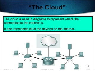
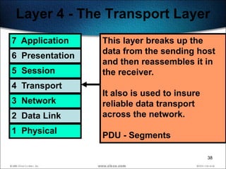
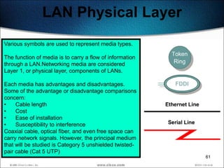
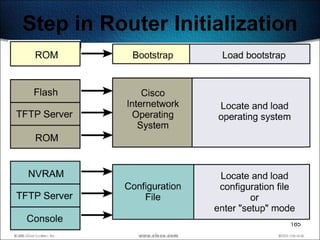
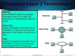
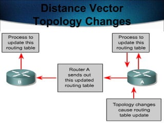
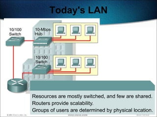
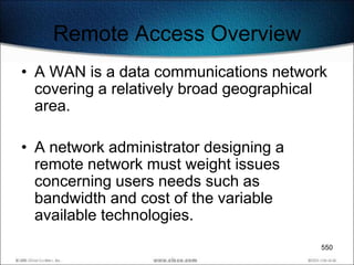
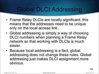
This document discusses networking devices and technologies used to connect local area networks (LANs) and wide area networks (WANs). It describes common physical layer components used in Ethernet LANs such as twisted pair cable, fiber optic cable, and connectors. It also discusses serial connection options and devices used for WAN connections including CSU/DSUs and their roles as data terminal equipment (DTE) and data circuit-terminating equipment (DCE).


![Setup Mode
Setup is not intended as the mode for entering complex protocol features in the
router. The purpose of the setup mode is to permit the administrator to install a
minimal configuration for a router, unable to locate a configuration from another
source.
In the setup mode, default answers appear in square brackets [ ] following the
question. Press the Enter key to use these defaults.
During the setup process, Ctrl-C can be pressed at any time to terminate the
process. When setup is terminated using Ctrl-C, all interfaces will be
administratively shutdown.
When the configuration process is completed in setup mode, the following options
will be displayed:
[0] Go to the IOS command prompt without saving this config.
[1] Return back to the setup without saving this config.
[2] Save this configuration to nvram and exit.
Enter your selection [2]: 180](https://image.slidesharecdn.com/ccnapresentation-13020219098042-phpapp02/85/Ccna-Presentation-180-320.jpg)


![Configuring Default Routes
Default routes are used to route packets with destinations that do
not match any of the other routes in the routing table.
A default route is actually a special static route that uses this format:
ip route 0.0.0.0 0.0.0.0 [next-hop-address | outgoing interface]
This is sometimes referred to as a ―Quad-Zero‖ route.
Example using next hop address:
Router(config)#ip route 0.0.0.0 0.0.0.0 172.16.4.1
Example using the exit interface:
Router(config)#ip route 0.0.0.0 0.0.0.0 s0/0 240](https://image.slidesharecdn.com/ccnapresentation-13020219098042-phpapp02/85/Ccna-Presentation-240-320.jpg)


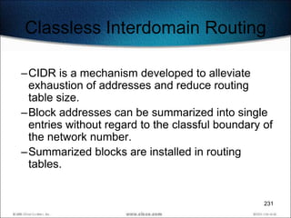
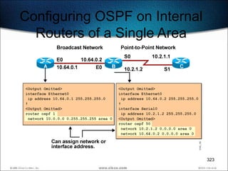
![Configuring Basic OSPF:
Single Area
Router(config)#
router ospf process-id
• Turns on one or more OSPF routing processes in
the IOS software.
Router(config-router)#
network address inverse-mask area [area-id]
• Router OSPF subordinate command that defines
the interfaces (by network number) that OSPF
will run on. Each network number must be
defined to a specific area.
322](https://image.slidesharecdn.com/ccnapresentation-13020219098042-phpapp02/85/Ccna-Presentation-322-320.jpg)

![Verifying OSPF Operation
(Cont.)
Router#
show ip ospf
• Displays the OSPF router ID, timers, and statistics
Router#
show ip ospf neighbor [detail]
• Displays information about the OSPF neighbors,
including Designated Router (DR) and Backup
Designated Router (BDR) information on
broadcast networks
325](https://image.slidesharecdn.com/ccnapresentation-13020219098042-phpapp02/85/Ccna-Presentation-325-320.jpg)
![The show ip route ospf
Command
RouterA# show ip route ospf
Codes: C - connected, S - static, I - IGRP, R - RIP, M - mobile,
B - BGP, D - EIGRP, EX - EIGRP external, O - OSPF,
IA - OSPF inter area, E1 - OSPF external type 1,
E2 - OSPF external type 2, E - EGP, i - IS-IS, L1 - IS-IS
level-1, L2 - IS-IS level-2, * - candidate default
Gateway of last resort is not set
10.0.0.0 255.255.255.0 is subnetted, 2 subnets
O 10.2.1.0 [110/10] via 10.64.0.2, 00:00:50, Ethernet0
326](https://image.slidesharecdn.com/ccnapresentation-13020219098042-phpapp02/85/Ccna-Presentation-326-320.jpg)


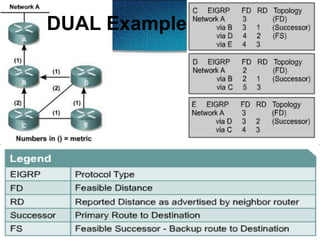


![show ip eigrp topology
show ip eigrp topology
[active | pending | successors]
360](https://image.slidesharecdn.com/ccnapresentation-13020219098042-phpapp02/85/Ccna-Presentation-360-320.jpg)


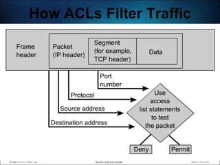


![Standard ACLs
Standard ACLs check the source address of IP packets that are routed.
The comparison will result in either permit or deny access for an entire protocol
suite, based on the network, subnet, and host addresses.
The standard version of the access-list global configuration command is used to
define a standard ACL with a number in the range of 1 to 99 (also from 1300 to
1999 in recent IOS).
If there is no wildcard mask. the default mask is used, which is 0.0.0.0.
(This only works with Standard ACLs and is the same thing as using host.)
The full syntax of the standard ACL command is:
Router(config)#access-list access-list-number
{deny | permit} source [source-wildcard ] [log]
The no form of this command is used to remove a standard ACL. This is the syntax:
384
Router(config)#no access-list access-list-number](https://image.slidesharecdn.com/ccnapresentation-13020219098042-phpapp02/85/Ccna-Presentation-384-320.jpg)


![Static NAT Configuration
• To form NAT table
Router(config)#IP Nat inside source static [inside local
source IP address] [inside global source IP address]
• Assign NAT to an Interface
Router(config)#Interface [Serial x/y]
Router(config-if)#IP NAT [Inside]
• See Example
450
Fig. 2 Address shortage and possible solutions (TI1332EU02TI_0003 New Address Concepts, 5)](https://image.slidesharecdn.com/ccnapresentation-13020219098042-phpapp02/85/Ccna-Presentation-450-320.jpg)


![Dynamic NAT Configuration
• Specify inside addresses to be translated
Router(config)#IP Nat inside source list [standard Access
List number] pool [NAT Pool Name]
• Specify NAT pool
Router(config)#IP Nat pool [NAT Pool Name] [First inside
global address] [Last inside global address] netmask
[subnet mask]
• Assign NAT to an Interface
Router(config)#Interface [Serial x/y]
Router(config-if)#IP NAT [Inside]
• See Example
453
Fig. 2 Address shortage and possible solutions (TI1332EU02TI_0003 New Address Concepts, 5)](https://image.slidesharecdn.com/ccnapresentation-13020219098042-phpapp02/85/Ccna-Presentation-453-320.jpg)

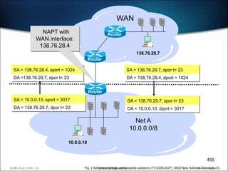

![PAT Configuration
• Specify inside addresses to be translated
Router(config)#IP Nat inside source list [standard Access
List number] pool [NAT Pool Name] overload
• Specify PAT pool
Router(config)#IP Nat pool [NAT Pool Name] [First inside
global address] [Last inside global address] netmask
[subnet mask]
• Assign PAT to an Interface
Router(config)#Interface [Serial x/y]
Router(config-if)#IP NAT [Inside]
• See Example
457
Fig. 2 Address shortage and possible solutions (TI1332EU02TI_0003 New Address Concepts, 5)](https://image.slidesharecdn.com/ccnapresentation-13020219098042-phpapp02/85/Ccna-Presentation-457-320.jpg)


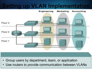


![Verifying the VLAN
Configuration
Switch#show vlan [id | name] [vlan_num | vlan_name]
VLAN Name Status Ports
---- -------------------------------- --------- -------------------------------
1 default active Fa0/1, Fa0/2, Fa0/5, Fa0/7
Fa0/8, Fa0/9, Fa0/11, Fa0/12
Gi0/1, Gi0/2
2 VLAN0002 active
51 VLAN0051 active
52 VLAN0052 active
…
VLAN Type SAID MTU Parent RingNo BridgeNo Stp BrdgMode Trans1 Trans2
---- ----- ---------- ----- ------ ------ -------- ---- -------- ------ ------
1 enet 100001 1500 - - - - - 1002 1003
2 enet 100002 1500 - - - - - 0 0
51 enet 100051 1500 - - - - - 0 0
52 enet 100052 1500 - - - - - 0 0
…
Remote SPAN VLANs
------------------------------------------------------------------------------
Primary Secondary Type Ports 526
------- --------- ----------------- ------------------------------------------](https://image.slidesharecdn.com/ccnapresentation-13020219098042-phpapp02/85/Ccna-Presentation-526-320.jpg)
![Verifying the VLAN Port
Configuration
Switch#show running-config interface {fastethernet |
gigabitethernet} slot/port
• Displays the running configuration of the interface
Switch#show interfaces [{fastethernet | gigabitethernet}
slot/port] switchport
• Displays the switch port configuration of the interface
Switch#show mac-address-table interface interface-id [vlan
vlan-id] [ | {begin | exclude | include} expression]
• Displays the MAC address table information for the specified
interface in the specified VLAN
527](https://image.slidesharecdn.com/ccnapresentation-13020219098042-phpapp02/85/Ccna-Presentation-527-320.jpg)

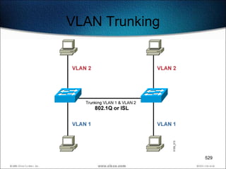


![Configuring ISL Trunking
Switch(config)#interface fastethernet 2/1
• Enters interface configuration mode
Switch(config-if)#switchport mode trunk
• Configures the interface as a Layer 2 trunk
Switch(config-if)#switchport trunk encapsulation [isl|dot1q]
• Selects the encapsulation
533](https://image.slidesharecdn.com/ccnapresentation-13020219098042-phpapp02/85/Ccna-Presentation-533-320.jpg)
![Verifying ISL Trunking
Switch#show running-config interface {fastethernet |
gigabitethernet} slot/port
Switch#show interfaces [fastethernet | gigabitethernet]
slot/port [ switchport | trunk ]
Switch#show interfaces fastethernet 2/1 trunk
Port Mode Encapsulation Status Native VLAN
Fa2/1 desirable isl trunking 1
Port VLANs allowed on trunk
Fa2/1 1-1005
Port VLANs allowed and active in management domain
Fa2/1 1-2,1002-1005
Port VLANs in spanning tree forwarding state and not pruned
Fa2/1 1-2,1002-1005
534](https://image.slidesharecdn.com/ccnapresentation-13020219098042-phpapp02/85/Ccna-Presentation-534-320.jpg)

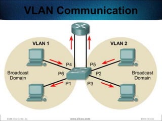
![Verifying 802.1Q Trunking
Switch#show running-config interface {fastethernet |
gigabitethernet} slot/port
Switch#show interfaces [fastethernet | gigabitethernet]
slot/port [ switchport | trunk ]
Switch#show interfaces gigabitEthernet 0/1 switchport
Name: Gi0/1
Switchport: Enabled
Administrative Mode: trunk
Operational Mode: trunk
Administrative Trunking Encapsulation: dot1q
Operational Trunking Encapsulation: dot1q
Negotiation of Trunking: On
Access Mode VLAN: 1 (default)
Trunking Native Mode VLAN: 1 (default)
Trunking VLANs Enabled: ALL
Pruning VLANs Enabled: 2-1001
. . .
537](https://image.slidesharecdn.com/ccnapresentation-13020219098042-phpapp02/85/Ccna-Presentation-537-320.jpg)


![PPP Configuration Commands
• To enable PPP
– Router(config-if)#encapsulation ppp
• To configure PAP authentication
– Router(Config-if)#ppp authentication pap
– Router(Config-if)#ppp pap username .. password ..
• To configure Compression
– Router(Config-if)#compress [predictor|stack|mppc]
571](https://image.slidesharecdn.com/ccnapresentation-13020219098042-phpapp02/85/Ccna-Presentation-571-320.jpg)


![Ccna presentation{complete]](https://cdn.slidesharecdn.com/ss_thumbnails/ccnapresentationcomplete-130702012220-phpapp02-thumbnail.jpg?width=640&height=640&fit=bounds)


