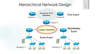
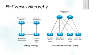
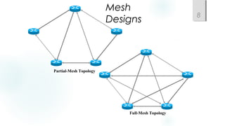
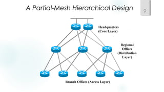
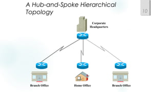
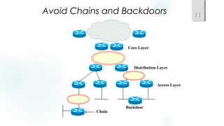
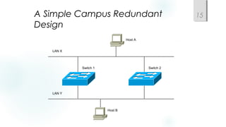
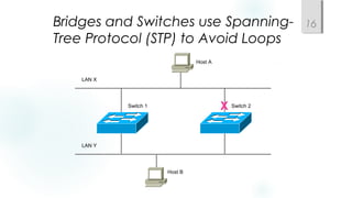
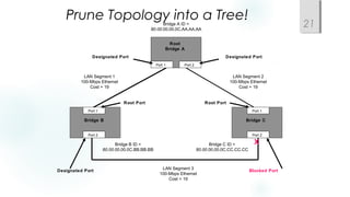
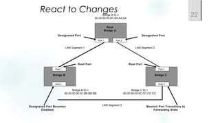
Top-Down Network Design
Chapter Five
Designing a Network Topology
Copyright 2010 Cisco Press & Priscilla Oppenheimer
Topology 2
• A branch of mathematics concerned with those
properties of geometric configurations that are
unaltered by elastic deformations such as
stretching or twisting
• A term used in the computer networking field to
describe the structure of a network
Network Topology Design
Themes
 Hierarchy
 Redundancy
 Modularity
 Well-defined entries and exits
 Protected perimeters
3
Why Use a Hierarchical Model?
 Reduces workload on network devices
 Avoids devices having to communicate with too many other
devices (reduces “CPU adjacencies”)
 Constrains broadcast domains
 Enhances simplicity and understanding
 Facilitates changes
 Facilitates scaling to a larger size
4
Hierarchical Network Design 5
Enterprise WAN
Backbone
Campus A Campus B
Campus C
Building C-1 Building C-2
Campus C Backbone
Core Layer
Distribution
Layer
Access Layer
Cisco’s Hierarchical Design
Model
 A core layer of high-end routers and switches that are optimized for
availability and speed
 A distribution layer of routers and switches that implement policies
and segment traffic
 An access layer that connects users via hubs, switches, and other
devices
6
Flat Versus Hierarchy 7
Flat Loop Topology
Headquarters in
Medford
Grants Pass
Branch Office
Ashland
Branch
Office
Klamath Falls
Branch Office
Headquarters in
Medford
Ashland
Branch
Office
Klamath Falls
Branch Office
Grants Pass
Branch
Office
White City
Branch Office
Hierarchical Redundant Topology
Mesh
Designs
8
Partial-Mesh Topology
Full-Mesh Topology
A Partial-Mesh Hierarchical Design 9
Headquarters
(Core Layer)
Branch Offices (Access Layer)
Regional
Offices
(Distribution
Layer)
A Hub-and-Spoke Hierarchical
Topology 10
Corporate
Headquarters
Branch Office Branch OfficeHome Office
Avoid Chains and Backdoors 11
Core Layer
Distribution Layer
Access Layer
Chain
Backdoor
How Do You Know When You Have
a Good Design?
 When you already know how to add a new
building, floor, WAN link, remote site, e-
commerce service, and so on
 When new additions cause only local
change, to the directly-connected devices
 When your network can double or triple in
size without major design changes
 When troubleshooting is easy because there
are no complex protocol interactions to
wrap your brain around
12
Cisco’s SAFE Security Reference
Architecture
13
Campus Topology Design
 Use a hierarchical, modular approach
 Minimize the size of bandwidth domains
 Minimize the size of broadcast domains
 Provide redundancy
 Mirrored servers
 Multiple ways for workstations to reach a router for off-net
communications
14
A Simple Campus Redundant
Design
15
Host A
Host B
LAN X
LAN Y
Switch 1 Switch 2
Bridges and Switches use Spanning-
Tree Protocol (STP) to Avoid Loops
16
X
Host A
Host B
LAN X
LAN Y
Switch 1 Switch 2
Bridges (Switches) Running STP
 Participate with other bridges in the election of a single
bridge as the Root Bridge.
 Calculate the distance of the shortest path to the Root
Bridge and choose a port (known as the Root Port) that
provides the shortest path to the Root Bridge.
 For each LAN segment, elect a Designated Bridge and a
Designated Port on that bridge. The Designated Port is a
port on the LAN segment that is closest to the Root Bridge.
(All ports on the Root Bridge are Designated Ports.)
 Select bridge ports to be included in the spanning tree.
The ports selected are the Root Ports and Designated
Ports. These ports forward traffic. Other ports block traffic.
17
Elect a Root 18
Bridge B Bridge C
Bridge A ID =
80.00.00.00.0C.AA.AA.AA
Bridge B ID =
80.00.00.00.0C.BB.BB.BB
Bridge C ID =
80.00.00.00.0C.CC.CC.CC
Port 1
Port 2
Port 1
Port 2
Port 1 Port 2
LAN Segment 2
100-Mbps Ethernet
Cost = 19
LAN Segment 1
100-Mbps Ethernet
Cost = 19
LAN Segment 3
100-Mbps Ethernet
Cost = 19
Root
Bridge A
Lowest Bridge ID
Wins!
Determine Root Ports 19
Bridge B Bridge C
Root
Bridge A
Bridge A ID =
80.00.00.00.0C.AA.AA.AA
Bridge B ID =
80.00.00.00.0C.BB.BB.BB
Bridge C ID =
80.00.00.00.0C.CC.CC.CC
Port 1
Port 2
Port 1
Port 2
Port 1 Port 2
LAN Segment 2
100-Mbps Ethernet
Cost = 19
LAN Segment 1
100-Mbps Ethernet
Cost = 19
LAN Segment 3
100-Mbps Ethernet
Cost = 19
Root Port Root Port
Lowest Cost
Wins!
Determine Designated Ports
20
Bridge B Bridge C
Root
Bridge A
Bridge A ID =
80.00.00.00.0C.AA.AA.AA
Bridge B ID =
80.00.00.00.0C.BB.BB.BB
Bridge C ID =
80.00.00.00.0C.CC.CC.CC
Port 1
Port 2
Port 1
Port 2
Port 1 Port 2
LAN Segment 2
100-Mbps Ethernet
Cost = 19
LAN Segment 1
100-Mbps Ethernet
Cost = 19
LAN Segment 3
100-Mbps Ethernet
Cost = 19
Root Port Root Port
Designated Port Designated Port
Designated Port
Lowest Bridge ID
Wins!
Bridge B Bridge C
Root
Bridge A
Bridge A ID =
80.00.00.00.0C.AA.AA.AA
Bridge B ID =
80.00.00.00.0C.BB.BB.BB
Bridge C ID =
80.00.00.00.0C.CC.CC.CC
Port 1
Port 2
Port 1
Port 2
Port 1 Port 2
LAN Segment 2
100-Mbps Ethernet
Cost = 19
LAN Segment 1
100-Mbps Ethernet
Cost = 19
LAN Segment 3
100-Mbps Ethernet
Cost = 19
Root Port Root Port
Designated Port Designated Port
Designated Port Blocked Port
X
Prune Topology into a Tree!
21
React to Changes
22
Bridge B Bridge C
Root
Bridge A
Bridge A ID =
80.00.00.00.0C.AA.AA.AA
Bridge B ID =
80.00.00.00.0C.BB.BB.BB
Bridge C ID =
80.00.00.00.0C.CC.CC.CC
Port 1
Port 2
Port 1
Port 2
Port 1 Port 2
LAN Segment 2LAN Segment 1
LAN Segment 3
Root Port Root Port
Designated Port Designated Port
Designated Port Becomes
Disabled
Blocked Port Transitions to
Forwarding State
Scaling the Spanning Tree Protocol
 Keep the switched network small
 It shouldn’t span more than seven switches
 Use BPDU skew detection on Cisco switches
 Use IEEE 802.1w
 Provides rapid reconfiguration of the spanning tree
 Also known as RSTP
23
Virtual LANs (VLANs)
 An emulation of a standard LAN that allows data transfer
to take place without the traditional physical restraints
placed on a network
 A set of devices that belong to an administrative group
 Designers use VLANs to constrain broadcast traffic
24
VLANs versus Real LANs 25
Switch A
Station A1 Station A2 Station A3
Network A
Switch B
Station B1 Station B2 Station B3
Network B
A Switch with VLANs 26
Station A1 Station A2 Station A3
VLAN A
Station B1 Station B2 Station B3
VLAN B
VLANs Span Switches 27
Switch A
Station B1 Station B2 Station B3
Switch B
Station B4 Station B5 Station B6
Station A1 Station A2 Station A3 Station A4 Station A5 Station A6
VLAN B
VLAN A
VLAN B
VLAN A
WLANs and VLANs
 A wireless LAN (WLAN) is often implemented as a VLAN
 Facilitates roaming
 Users remain in the same VLAN and IP subnet as they
roam, so there’s no need to change addressing
information
 Also makes it easier to set up filters (access control lists) to
protect the wired network from wireless users
28
Workstation-to-Router
Communication
 Proxy ARP (not a good idea)
 Listen for route advertisements (not a great idea either)
 ICMP router solicitations (not widely used)
 Default gateway provided by DHCP (better idea but no
redundancy)
 Use Hot Standby Router Protocol (HSRP) for redundancy
29
HSRP 30
Active Router
Standby Router
Virtual Router
Workstation
Enterprise Internetwork
Multihoming the Internet Connection 31
Enterprise
Enterprise
Enterprise
ISP 1
ISP 1 ISP 2
ISP 1
ISP 1 ISP 2
Enterprise
Option A
Option B
Option C
Option D
Paris NY
Paris NY
Security Topologies 32
Enterprise
Network
DMZ
Web, File, DNS, Mail Servers
Internet
Security Topologies 33
Internet
Enterprise Network
DMZ
Web, File, DNS, Mail Servers
Firewall
Summary
 Use a systematic, top-down approach
 Plan the logical design before the physical design
 Topology design should feature hierarchy, redundancy,
modularity, and security
34
Review Questions
 Why are hierarchy and modularity
important for network designs?
 What are the three layers of Cisco’s
hierarchical network design?
 What are the major components of Cisco’s
enterprise composite network model?
 What are the advantages and
disadvantages of the various options for
multihoming an Internet connection?
35

Chapter05

  • 1.
    Top-Down Network Design ChapterFive Designing a Network Topology Copyright 2010 Cisco Press & Priscilla Oppenheimer
  • 2.
    Topology 2 • Abranch of mathematics concerned with those properties of geometric configurations that are unaltered by elastic deformations such as stretching or twisting • A term used in the computer networking field to describe the structure of a network
  • 3.
    Network Topology Design Themes Hierarchy  Redundancy  Modularity  Well-defined entries and exits  Protected perimeters 3
  • 4.
    Why Use aHierarchical Model?  Reduces workload on network devices  Avoids devices having to communicate with too many other devices (reduces “CPU adjacencies”)  Constrains broadcast domains  Enhances simplicity and understanding  Facilitates changes  Facilitates scaling to a larger size 4
  • 5.
    Hierarchical Network Design5 Enterprise WAN Backbone Campus A Campus B Campus C Building C-1 Building C-2 Campus C Backbone Core Layer Distribution Layer Access Layer
  • 6.
    Cisco’s Hierarchical Design Model A core layer of high-end routers and switches that are optimized for availability and speed  A distribution layer of routers and switches that implement policies and segment traffic  An access layer that connects users via hubs, switches, and other devices 6
  • 7.
    Flat Versus Hierarchy7 Flat Loop Topology Headquarters in Medford Grants Pass Branch Office Ashland Branch Office Klamath Falls Branch Office Headquarters in Medford Ashland Branch Office Klamath Falls Branch Office Grants Pass Branch Office White City Branch Office Hierarchical Redundant Topology
  • 8.
  • 9.
    A Partial-Mesh HierarchicalDesign 9 Headquarters (Core Layer) Branch Offices (Access Layer) Regional Offices (Distribution Layer)
  • 10.
    A Hub-and-Spoke Hierarchical Topology10 Corporate Headquarters Branch Office Branch OfficeHome Office
  • 11.
    Avoid Chains andBackdoors 11 Core Layer Distribution Layer Access Layer Chain Backdoor
  • 12.
    How Do YouKnow When You Have a Good Design?  When you already know how to add a new building, floor, WAN link, remote site, e- commerce service, and so on  When new additions cause only local change, to the directly-connected devices  When your network can double or triple in size without major design changes  When troubleshooting is easy because there are no complex protocol interactions to wrap your brain around 12
  • 13.
    Cisco’s SAFE SecurityReference Architecture 13
  • 14.
    Campus Topology Design Use a hierarchical, modular approach  Minimize the size of bandwidth domains  Minimize the size of broadcast domains  Provide redundancy  Mirrored servers  Multiple ways for workstations to reach a router for off-net communications 14
  • 15.
    A Simple CampusRedundant Design 15 Host A Host B LAN X LAN Y Switch 1 Switch 2
  • 16.
    Bridges and Switchesuse Spanning- Tree Protocol (STP) to Avoid Loops 16 X Host A Host B LAN X LAN Y Switch 1 Switch 2
  • 17.
    Bridges (Switches) RunningSTP  Participate with other bridges in the election of a single bridge as the Root Bridge.  Calculate the distance of the shortest path to the Root Bridge and choose a port (known as the Root Port) that provides the shortest path to the Root Bridge.  For each LAN segment, elect a Designated Bridge and a Designated Port on that bridge. The Designated Port is a port on the LAN segment that is closest to the Root Bridge. (All ports on the Root Bridge are Designated Ports.)  Select bridge ports to be included in the spanning tree. The ports selected are the Root Ports and Designated Ports. These ports forward traffic. Other ports block traffic. 17
  • 18.
    Elect a Root18 Bridge B Bridge C Bridge A ID = 80.00.00.00.0C.AA.AA.AA Bridge B ID = 80.00.00.00.0C.BB.BB.BB Bridge C ID = 80.00.00.00.0C.CC.CC.CC Port 1 Port 2 Port 1 Port 2 Port 1 Port 2 LAN Segment 2 100-Mbps Ethernet Cost = 19 LAN Segment 1 100-Mbps Ethernet Cost = 19 LAN Segment 3 100-Mbps Ethernet Cost = 19 Root Bridge A Lowest Bridge ID Wins!
  • 19.
    Determine Root Ports19 Bridge B Bridge C Root Bridge A Bridge A ID = 80.00.00.00.0C.AA.AA.AA Bridge B ID = 80.00.00.00.0C.BB.BB.BB Bridge C ID = 80.00.00.00.0C.CC.CC.CC Port 1 Port 2 Port 1 Port 2 Port 1 Port 2 LAN Segment 2 100-Mbps Ethernet Cost = 19 LAN Segment 1 100-Mbps Ethernet Cost = 19 LAN Segment 3 100-Mbps Ethernet Cost = 19 Root Port Root Port Lowest Cost Wins!
  • 20.
    Determine Designated Ports 20 BridgeB Bridge C Root Bridge A Bridge A ID = 80.00.00.00.0C.AA.AA.AA Bridge B ID = 80.00.00.00.0C.BB.BB.BB Bridge C ID = 80.00.00.00.0C.CC.CC.CC Port 1 Port 2 Port 1 Port 2 Port 1 Port 2 LAN Segment 2 100-Mbps Ethernet Cost = 19 LAN Segment 1 100-Mbps Ethernet Cost = 19 LAN Segment 3 100-Mbps Ethernet Cost = 19 Root Port Root Port Designated Port Designated Port Designated Port Lowest Bridge ID Wins!
  • 21.
    Bridge B BridgeC Root Bridge A Bridge A ID = 80.00.00.00.0C.AA.AA.AA Bridge B ID = 80.00.00.00.0C.BB.BB.BB Bridge C ID = 80.00.00.00.0C.CC.CC.CC Port 1 Port 2 Port 1 Port 2 Port 1 Port 2 LAN Segment 2 100-Mbps Ethernet Cost = 19 LAN Segment 1 100-Mbps Ethernet Cost = 19 LAN Segment 3 100-Mbps Ethernet Cost = 19 Root Port Root Port Designated Port Designated Port Designated Port Blocked Port X Prune Topology into a Tree! 21
  • 22.
    React to Changes 22 BridgeB Bridge C Root Bridge A Bridge A ID = 80.00.00.00.0C.AA.AA.AA Bridge B ID = 80.00.00.00.0C.BB.BB.BB Bridge C ID = 80.00.00.00.0C.CC.CC.CC Port 1 Port 2 Port 1 Port 2 Port 1 Port 2 LAN Segment 2LAN Segment 1 LAN Segment 3 Root Port Root Port Designated Port Designated Port Designated Port Becomes Disabled Blocked Port Transitions to Forwarding State
  • 23.
    Scaling the SpanningTree Protocol  Keep the switched network small  It shouldn’t span more than seven switches  Use BPDU skew detection on Cisco switches  Use IEEE 802.1w  Provides rapid reconfiguration of the spanning tree  Also known as RSTP 23
  • 24.
    Virtual LANs (VLANs) An emulation of a standard LAN that allows data transfer to take place without the traditional physical restraints placed on a network  A set of devices that belong to an administrative group  Designers use VLANs to constrain broadcast traffic 24
  • 25.
    VLANs versus RealLANs 25 Switch A Station A1 Station A2 Station A3 Network A Switch B Station B1 Station B2 Station B3 Network B
  • 26.
    A Switch withVLANs 26 Station A1 Station A2 Station A3 VLAN A Station B1 Station B2 Station B3 VLAN B
  • 27.
    VLANs Span Switches27 Switch A Station B1 Station B2 Station B3 Switch B Station B4 Station B5 Station B6 Station A1 Station A2 Station A3 Station A4 Station A5 Station A6 VLAN B VLAN A VLAN B VLAN A
  • 28.
    WLANs and VLANs A wireless LAN (WLAN) is often implemented as a VLAN  Facilitates roaming  Users remain in the same VLAN and IP subnet as they roam, so there’s no need to change addressing information  Also makes it easier to set up filters (access control lists) to protect the wired network from wireless users 28
  • 29.
    Workstation-to-Router Communication  Proxy ARP(not a good idea)  Listen for route advertisements (not a great idea either)  ICMP router solicitations (not widely used)  Default gateway provided by DHCP (better idea but no redundancy)  Use Hot Standby Router Protocol (HSRP) for redundancy 29
  • 30.
    HSRP 30 Active Router StandbyRouter Virtual Router Workstation Enterprise Internetwork
  • 31.
    Multihoming the InternetConnection 31 Enterprise Enterprise Enterprise ISP 1 ISP 1 ISP 2 ISP 1 ISP 1 ISP 2 Enterprise Option A Option B Option C Option D Paris NY Paris NY
  • 32.
  • 33.
    Security Topologies 33 Internet EnterpriseNetwork DMZ Web, File, DNS, Mail Servers Firewall
  • 34.
    Summary  Use asystematic, top-down approach  Plan the logical design before the physical design  Topology design should feature hierarchy, redundancy, modularity, and security 34
  • 35.
    Review Questions  Whyare hierarchy and modularity important for network designs?  What are the three layers of Cisco’s hierarchical network design?  What are the major components of Cisco’s enterprise composite network model?  What are the advantages and disadvantages of the various options for multihoming an Internet connection? 35

Editor's Notes

  • #3 Did you know that according to topologists, a coffee cup and donut are the same shape? If they were made of clay, for example, consider how easy it would be to mold the one to look like the other, while retaining the most significant characteristics (such as the roundedness and the hole). Just like with coffee and donuts made of clay, in the networking field, during the logical design phase, we are more concerned with the overall architecture, shape, size, and interconnectedness of a network, than with the physical details. For more information regarding topology, coffee, and donuts, see: http://en.wikipedia.org/wiki/Topology
  • #13 Said by Dr. Peter Welcher, consultant and author of many networking articles in magazines, etc.
  • #18 If all ports have equal distance to the Root Bridge, then the Designated Port is chosen by lowest sender Bridge ID. If the IDs are the same, then the port is chosen by lowest Port ID. In general, STP checks for the best information by using these four criteria in the following order: Lowest Root Bridge ID Lowest path cost to the Root Bridge Lowest sender Bridge ID Lowest Port ID See Top-Down Network Design for more details.
  • #26 To understand VLANs, it helps to think about real (non-virtual) LANs first. Imagine two switches that are not connected to each other in any way. Switch A connects stations in Network A and Switch B connects stations in Network B, When Station A1 sends a broadcast, Station A2 and Station A3 receive the broadcast, but none of the stations in Network B receive the broadcast, because the two switches are not connected. This same configuration can be implemented through configuration options in a single switch, with the result looking like the next slide.
  • #27 Through the configuration of the switch there are now two virtual LANs implemented in a single switch, instead of two separate physical LANs. This is the beauty of VLANs. The broadcast, multicast, and unknown-destination traffic originating with any member of VLAN A is forwarded to all other members of VLAN A, and not to a member of VLAN B. VLAN A has the same properties as a physically separate LAN bounded by routers. The protocol behavior in this slide is exactly the same as the protocol behavior in the previous slide.
  • #28 VLANs can span multiple switches. In this slide, both switches contain stations that are members of VLAN A and VLAN B. This design introduces a new problem, the solution to which is specified in the IEEE 802.1Q standard and the Cisco proprietary Inter-Switch Link (ISL) protocol. The problem has to do with the forwarding of broadcast, multicast, or unknown-destination frames from a member of a VLAN on one switch to the members of the same VLAN on the other switch. In this slide, all frames going from Switch A to Switch B take the same interconnection path. The 802.1Q standard and Cisco's ISL protocol define a method for Switch B to recognize whether an incoming frame belongs to VLAN A or to VLAN B. As a frame leaves Switch A, a special header is added to the frame, called the VLAN tag. The VLAN tag contains a VLAN identifier (ID) that specifies to which VLAN the frame belongs. Because both switches have been configured to recognize VLAN A and VLAN B, they can exchange frames across the interconnection link, and the recipient switch can determine the VLAN into which those frames should be sent by examining the VLAN tag. The link between the two switches is sometimes called a trunk link or simply a trunk. Trunk links allow the network designer to stitch together VLANs that span multiple switches. A major design consideration is determining the scope of each VLAN and how many switches it should span. Most designers try to keep the scope small. Each VLAN is a broadcast domain. In general, a single broadcast domain should be limited to a few hundred workstations (or other devices, such as IP phones).