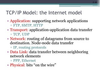
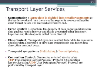
Network Model
1
Outline
2.1 PROTOCOL LAYERING
▫ 2.1.1 Scenarios
▫ 2.1.2 Principles of Protocol Layering
▫ 2.1.3 Logical Connections
2.2 TCP/IP PROTOCOL SUITE
▫ 2.2.1 Layered Architecture
▫ 2.2.2 Layers in the TCP/IP Protocol Suite
▫ 2.2.3 Description of Each Layer
2.3 THE OSI MODEL
▫ 2.3.1 OSI versus TCP/IP
▫ 2.3.2 Lack of OSI Model’s Success
2
Layered Tasks
• Computer networks are complex systems
▫ Tasks involve varieties of hardware and software
components, and protocols
• Networking task is divided into several subtasks,
or layers.
3
Why layering?
• Networks are complex!
• We need a way to organize the structure of
network functionalities and to reduce the
design complexities
• Benefits of layering
▫ Interoperability
▫ Reuse
▫ Hiding underlying details
2-4
Protocol interfaces
• Each protocol offers an interface to its users, and
expects one from the layers on which it builds
▫ Syntax and semantics
 Data formats
 Interface characteristics, e.g. IP service model
• Protocols build upon each other
▫ Add value
 E.g., a reliable protocol running on top of IP
▫ Reuse
 E.g., OS provides TCP, so apps don’t have to rewrite
2-5
Real World Example
• Communication between managers of two
companies
6
Communicate
Logical Connection
• Communication takes place thru many layers
7
Logical communication
Secretary:
types a letter
Delivery boy:
drops the letter
Secretary:
reads and reports
the message
Delivery boy:
takes the letter
Post office:
Processes and routes the letter
Postal truck
Network Model
• Network models are responsible or establishing
a connection among the sender and receiver and
transmitting the data.
• There are two computer network models on
which data communication process relies :
▫ OSI Model
▫ TCP/IP Model .
10
TCP/IP Model
• The TCP/IP model was developed prior to the OSI model.
• The TCP/IP model is not exactly similar to the OSI model.
• The TCP/IP model consists of five layers: the application layer,
transport layer, network layer, data link layer and physical
layer.
• The first four layers provide physical standards, network
interface, internetworking, and transport functions that
correspond to the first four layers of the OSI model and these
four layers are represented in TCP/IP model by a single layer
called the application layer.
• TCP/IP is a hierarchical protocol made up of interactive
modules, and each of them provides specific functionality.
11
TCP/Internet Layer Model
Application Layer
Transport Layer
Network Layer
Data Link Layer
Physical Layer
12
• The Internet Protocol Stack
User
Transmission
Medium
Hardware
Software
TCP/IP Model: the Internet model
Application
Transport
Network
Data link
Physical1
2
3
4
Network
Data link
Physical
Application
Transport
Network
Data link
Physical
5
• Each layer relies on services from layer below
• Each layer exports services to layer above
• Interface between layers defines interaction
▫ Hides implementation details
▫ Layers can change without disturbing other layers
2-13
TCP/IP Model: the Internet model
• Application: supporting network applications
▫ FTP, SMTP, HTTP
• Transport: application-application data transfer
▫ TCP, UDP
• Network: routing of datagrams from source to
destination. Node-node data transfer
▫ IP, routing protocols
• Data Link: data transfer between neighboring
network elements
▫ PPP, Ethernet
• Physical: bits “on the wire”
2-14
15
16
Application Layer
• It is the topmost layer in the TCP/IP model.
• It is responsible for handling high-level protocols, issues of
representation.
• This layer allows the user to interact with the application.
• It facilitates the user to use the services of the network.
• It is used to develop network-based applications.
• It provides user services like user login, naming network devices,
formatting messages, and e-mails, transfer of files etc.
• When one application layer protocol wants to communicate with
another application layer, it forwards its data to the transport
layer.
17
Application Layer
• The only layer to interact with user
18
Responsible for providing services to the user
SMTP HTTP FTP SMTP HTTP FTP
Data
Data H5
Application
Layer
to Transport from Transport
Data H5
Data
Logical communication
Transport Layer
• The transport layer is a 4th layer from the top.
• It is responsible for end to end data transmission
service using connection oriented or either through
connection-less protocols.
• TCP and UDP are two transport layer protocols that
provide a different set of services to the network
layer.
• It provide multiplexing/demultiplexing service.
• It also provides other services such as reliable data
transfer, bandwidth guarantees, and delay
guarantees.
19
Transport Layer
• Duties/services
▫ Service-point addressing/Port Address
▫ Segmentation and reassembly
▫ Connection control
▫ Flow control (end-to-end)
▫ Error control (end-to-end)
20
Responsible for delivery of a message
from one process to another
Transport Layer Services
• Segmentation : Large data is divided into smaller segments at
the senders end and then these smaller segments are recombined in
exact format before it is received at receivers end.
• Error Control : Distortion, Un-delivery of data packets and noise in
data packets results in error and this is prevented using Transport
Layer too and this feature is called Error Control.
• Flow Control : Transport-Layer ensures that faster data transmission
and slow data absorption or slow data transmission and faster data
absorption must not occur.
• Transport-Layer performs Multiplexing & De-multiplexing.
• Connection Control: Connection oriented service using
TCP(Transmission Control Protocol) Protocol & Connection
less service using UDP(User Data-gram Protocol) Protocol are
performed by transport layer.
21
Transport Layer
22
Transport
Layer
Data
Data1 Data2 Data3H4 H4 H4
to Network
Data
Data1 Data2 Data3H4 H4 H4
from Network
(segments)
Process Process … Process Process …
PORT # PORT #
Network Layer
• Duties/services
▫ Logical addressing
▫ Routing
23
Responsible for the delivery of packets
from the original source to the destination
Network Layer
24
Network
Layer
Data
from Transport
to Data Link
Data
to Transport
from Data Link
Data H3 Data H3
(packet)
Network Layer
25
Network 1
Network 6
Network 5
1.1 1.2
6.6
6.1
6.3
5.7
5.2
Network 3
3.8
3.3
Router
Data 1.1 5.7
1.1, 1.2, 6.1, 5.7, ... are logical addresses
R1
R3
R2
Data Link Layer
• Framing: The data link layer divides the stream of bits received from the network layer into
manageable data units called frames.
• Physical addressing: If frames are to be distributed to different systems on the network, the
data link layer adds a header to the frame to define the sender and/or receiver of the frame. If
the frame is intended for a system outside the sender's network, the receiver address is the
address of the device that connects the network to the next one.
• Flow control (hop-to-hop): A receiving node can receive the frames at a faster rate than it can
process the frame. Without flow control, the receiver's buffer can overflow, and frames can get
lost. To overcome this problem, the data link layer uses the flow control to prevent the sending
node on one side of the link from overwhelming the receiving node on another side of the link.
• Error control (hop-to-hop):The data link layer adds reliability to the physical layer by adding
mechanisms to detect and retransmit damaged or lost frames. It also uses a mechanism to
recognize duplicate frames. Error control is normally achieved through a trailer added to the
end of the frame.
• Access control:. When two or more devices are connected to the same link, data link layer
protocols are necessary to determine which device has control over the link at any given time.
26
Data Link Layer
27
Data Link
Layer
Data
from Network
to Physical
Data
to Network
from Physical
Data H2 Data H2
(frame)
T2 T2
Responsible for transmitting frames
from one hop (node) to the next
Data Link Layer
28
3B
A3, 3B, 82, 9F, ... are physical addresses
9F 82 A3
Data 9FT2 A3
Data
H2
Data Link Layer
29
Network 1
Network 6
Network 5
1.1 1.2
6.6
6.1
6.3
5.7
5.2
Network 3
3.8
3.3
Data 1.15.7
97 32
25
79
62
54
74
12
88
Data 1.15.7 2597
Data 1.15.7 6279
Data 1.15.7 7454
R1
R3
R2
Physical Layer
• Physical Layer is the bottom-most layer.
• It is associated with the electrical, mechanical
and transmission media .
• Physical layer deals with all the physical devices
that can be used for data communication.
30
The physical layer is responsible for movements of
individual bits from one hop (node) to the next
Physical Layer
31
Physical
Layer
Data
from Data Link to Data Link
Data
01001011 01001011
Transmission medium
(bits)
Physical Layer Functions
• Physical characteristics of interfaces and medium
• Representation of bits: Data consists of a stream of
bits (sequence of 0s or 1s) with no interpretation.
• Data rate: The number of bits sent per second.
• Synchronization of bits: the sender and the receiver
clocks must be synchronized.
• Line configuration: Point to Point or Multipoint
• Physical topology: Bus/ Star/Mesh…
• Transmission mode: Simplex/Half/Full
32
The Big Picture
33
L5 data H5
L4 data H4
L3 data H3
L2 dataT2 H2
0111011010101001010101001
L5 data H5
L4 data H4
L3 data H3
L2 dataT2 H2
0111010101010010101010101
5
4
3
2
1
5
4
3
2
1
Transmission medium
Network
D.L.
P.L.
D.L.
P.L.
Network
D.L.
P.L.
D.L.
P.L.
Internet Model
Application
Transport
Network
Data Link
Physical
34
Application
Transport
Network
Data Link
Physical
Transmission medium
sender
router
router
receiver
Internet Model
35
Protocol Suites
• A set of protocols must be constructed
▫ to ensure that the resulting communication
system is complete and efficient
• Each protocol should handle a part of
communication not handled by other protocols
• How can we guarantee that protocols work well
together?
▫ Instead of creating each protocol in isolation,
protocols are designed in complete, cooperative
sets called suites or families
36
36
Internet Protocol Suite
37
Layer Protocols
Application HTTP, FTP, Telnet, SMTP, ...
Transport TCP, UDP, SCTP, ...
Network IP (IPv4), IPv6, ICMP, IGMP, ...
Data Link Ethernet, Wi-Fi, PPP, ...
Physical RS-232, DSL, 10Base-T, ...
OSI Model
• OSI stands for Open System Interconnection.
• Before networks came into existence, computers could
only communicate from the same manufacturers.
• OSI was designed by ISO (International Organization for
Standardization) in late 1970’s.
• To break this barrier so that Computers from different
manufacturer could communicate with each other.
• OSI is a “Layered Approach”, which is a logical
representation of how Data Communication should
occur.
38
OSI Model
• OSI has 7 different layers
• Two new layers is added
▫ Presentation Layer
▫ Session Layer
• It is divided into two groups,
▫ Top 3 layers defines how
application within end
stations will communicate
with each other and with the
user (Software Layer).
▫ Bottom 4 layers defines how
actually data is transferred
(Hardware Layer).
▫ https://www.youtube.com/w
atch?v=fiMswfo45DQ
39
7.Application Layer
6.Presentation Layer
5.Session Layer
4.Transport Layer
3.Network Layer
2.Data Link Layer
1.Physical Layer
User
Transmission
Medium
Session Layer
• This layer is responsible for establishment of
connection, maintenance of sessions, authentication
and also ensures security.
• Duties/services
▫ Dialog Controller :
 Allows the two processes to establish, use and terminate a
connection.
 Communication in half-duplex or full-duplex.
▫ Synchronization :
 allows a process to add checkpoints
 data is re-synchronized
 Session recovery
40
Presentation Layer
• A Presentation layer is mainly concerned with the
syntax and semantics of the information exchanged
between the two systems.
• It acts as a data translator for a network.
• This layer is a part of the operating system that
converts the data from one presentation format to
another format.
• The Presentation layer is also known as the syntax
layer.
41
Presentation Layer functions
• Duties/services
▫ Data translation: For example, ASCII to EBCDIC.
▫ Encryption/Decryption
▫ Compression: Reduces the number of bits that
need to be transmitted on the network.
42
44
OSI TCP/IP
It is developed by ISO (International
Standard Organization)
It is developed by ARPANET (Advanced
Research Project Agency Network).
OSI refers to Open Systems
Interconnection.
TCP refers to Transmission Control Protocol.
OSI follows a vertical approach. TCP/IP follows a horizontal approach.
In the OSI model, the transport layer is
only connection-oriented.
A layer of the TCP/IP model is both
connection-oriented and connectionless.
Session and presentation layers are a
part of the OSI model.
There is no session and presentation layer in
the TCP model.
TCP/IP is more reliable OSI is less reliable
45

02 network models

  • 1.
  • 2.
    Outline 2.1 PROTOCOL LAYERING ▫2.1.1 Scenarios ▫ 2.1.2 Principles of Protocol Layering ▫ 2.1.3 Logical Connections 2.2 TCP/IP PROTOCOL SUITE ▫ 2.2.1 Layered Architecture ▫ 2.2.2 Layers in the TCP/IP Protocol Suite ▫ 2.2.3 Description of Each Layer 2.3 THE OSI MODEL ▫ 2.3.1 OSI versus TCP/IP ▫ 2.3.2 Lack of OSI Model’s Success 2
  • 3.
    Layered Tasks • Computernetworks are complex systems ▫ Tasks involve varieties of hardware and software components, and protocols • Networking task is divided into several subtasks, or layers. 3
  • 4.
    Why layering? • Networksare complex! • We need a way to organize the structure of network functionalities and to reduce the design complexities • Benefits of layering ▫ Interoperability ▫ Reuse ▫ Hiding underlying details 2-4
  • 5.
    Protocol interfaces • Eachprotocol offers an interface to its users, and expects one from the layers on which it builds ▫ Syntax and semantics  Data formats  Interface characteristics, e.g. IP service model • Protocols build upon each other ▫ Add value  E.g., a reliable protocol running on top of IP ▫ Reuse  E.g., OS provides TCP, so apps don’t have to rewrite 2-5
  • 6.
    Real World Example •Communication between managers of two companies 6 Communicate
  • 7.
    Logical Connection • Communicationtakes place thru many layers 7 Logical communication Secretary: types a letter Delivery boy: drops the letter Secretary: reads and reports the message Delivery boy: takes the letter Post office: Processes and routes the letter Postal truck
  • 8.
    Network Model • Networkmodels are responsible or establishing a connection among the sender and receiver and transmitting the data. • There are two computer network models on which data communication process relies : ▫ OSI Model ▫ TCP/IP Model . 10
  • 9.
    TCP/IP Model • TheTCP/IP model was developed prior to the OSI model. • The TCP/IP model is not exactly similar to the OSI model. • The TCP/IP model consists of five layers: the application layer, transport layer, network layer, data link layer and physical layer. • The first four layers provide physical standards, network interface, internetworking, and transport functions that correspond to the first four layers of the OSI model and these four layers are represented in TCP/IP model by a single layer called the application layer. • TCP/IP is a hierarchical protocol made up of interactive modules, and each of them provides specific functionality. 11
  • 10.
    TCP/Internet Layer Model ApplicationLayer Transport Layer Network Layer Data Link Layer Physical Layer 12 • The Internet Protocol Stack User Transmission Medium Hardware Software
  • 11.
    TCP/IP Model: theInternet model Application Transport Network Data link Physical1 2 3 4 Network Data link Physical Application Transport Network Data link Physical 5 • Each layer relies on services from layer below • Each layer exports services to layer above • Interface between layers defines interaction ▫ Hides implementation details ▫ Layers can change without disturbing other layers 2-13
  • 12.
    TCP/IP Model: theInternet model • Application: supporting network applications ▫ FTP, SMTP, HTTP • Transport: application-application data transfer ▫ TCP, UDP • Network: routing of datagrams from source to destination. Node-node data transfer ▫ IP, routing protocols • Data Link: data transfer between neighboring network elements ▫ PPP, Ethernet • Physical: bits “on the wire” 2-14
  • 13.
  • 14.
  • 15.
    Application Layer • Itis the topmost layer in the TCP/IP model. • It is responsible for handling high-level protocols, issues of representation. • This layer allows the user to interact with the application. • It facilitates the user to use the services of the network. • It is used to develop network-based applications. • It provides user services like user login, naming network devices, formatting messages, and e-mails, transfer of files etc. • When one application layer protocol wants to communicate with another application layer, it forwards its data to the transport layer. 17
  • 16.
    Application Layer • Theonly layer to interact with user 18 Responsible for providing services to the user SMTP HTTP FTP SMTP HTTP FTP Data Data H5 Application Layer to Transport from Transport Data H5 Data Logical communication
  • 17.
    Transport Layer • Thetransport layer is a 4th layer from the top. • It is responsible for end to end data transmission service using connection oriented or either through connection-less protocols. • TCP and UDP are two transport layer protocols that provide a different set of services to the network layer. • It provide multiplexing/demultiplexing service. • It also provides other services such as reliable data transfer, bandwidth guarantees, and delay guarantees. 19
  • 18.
    Transport Layer • Duties/services ▫Service-point addressing/Port Address ▫ Segmentation and reassembly ▫ Connection control ▫ Flow control (end-to-end) ▫ Error control (end-to-end) 20 Responsible for delivery of a message from one process to another
  • 19.
    Transport Layer Services •Segmentation : Large data is divided into smaller segments at the senders end and then these smaller segments are recombined in exact format before it is received at receivers end. • Error Control : Distortion, Un-delivery of data packets and noise in data packets results in error and this is prevented using Transport Layer too and this feature is called Error Control. • Flow Control : Transport-Layer ensures that faster data transmission and slow data absorption or slow data transmission and faster data absorption must not occur. • Transport-Layer performs Multiplexing & De-multiplexing. • Connection Control: Connection oriented service using TCP(Transmission Control Protocol) Protocol & Connection less service using UDP(User Data-gram Protocol) Protocol are performed by transport layer. 21
  • 20.
    Transport Layer 22 Transport Layer Data Data1 Data2Data3H4 H4 H4 to Network Data Data1 Data2 Data3H4 H4 H4 from Network (segments) Process Process … Process Process … PORT # PORT #
  • 21.
    Network Layer • Duties/services ▫Logical addressing ▫ Routing 23 Responsible for the delivery of packets from the original source to the destination
  • 22.
    Network Layer 24 Network Layer Data from Transport toData Link Data to Transport from Data Link Data H3 Data H3 (packet)
  • 23.
    Network Layer 25 Network 1 Network6 Network 5 1.1 1.2 6.6 6.1 6.3 5.7 5.2 Network 3 3.8 3.3 Router Data 1.1 5.7 1.1, 1.2, 6.1, 5.7, ... are logical addresses R1 R3 R2
  • 24.
    Data Link Layer •Framing: The data link layer divides the stream of bits received from the network layer into manageable data units called frames. • Physical addressing: If frames are to be distributed to different systems on the network, the data link layer adds a header to the frame to define the sender and/or receiver of the frame. If the frame is intended for a system outside the sender's network, the receiver address is the address of the device that connects the network to the next one. • Flow control (hop-to-hop): A receiving node can receive the frames at a faster rate than it can process the frame. Without flow control, the receiver's buffer can overflow, and frames can get lost. To overcome this problem, the data link layer uses the flow control to prevent the sending node on one side of the link from overwhelming the receiving node on another side of the link. • Error control (hop-to-hop):The data link layer adds reliability to the physical layer by adding mechanisms to detect and retransmit damaged or lost frames. It also uses a mechanism to recognize duplicate frames. Error control is normally achieved through a trailer added to the end of the frame. • Access control:. When two or more devices are connected to the same link, data link layer protocols are necessary to determine which device has control over the link at any given time. 26
  • 25.
    Data Link Layer 27 DataLink Layer Data from Network to Physical Data to Network from Physical Data H2 Data H2 (frame) T2 T2 Responsible for transmitting frames from one hop (node) to the next
  • 26.
    Data Link Layer 28 3B A3,3B, 82, 9F, ... are physical addresses 9F 82 A3 Data 9FT2 A3 Data H2
  • 27.
    Data Link Layer 29 Network1 Network 6 Network 5 1.1 1.2 6.6 6.1 6.3 5.7 5.2 Network 3 3.8 3.3 Data 1.15.7 97 32 25 79 62 54 74 12 88 Data 1.15.7 2597 Data 1.15.7 6279 Data 1.15.7 7454 R1 R3 R2
  • 28.
    Physical Layer • PhysicalLayer is the bottom-most layer. • It is associated with the electrical, mechanical and transmission media . • Physical layer deals with all the physical devices that can be used for data communication. 30 The physical layer is responsible for movements of individual bits from one hop (node) to the next
  • 29.
    Physical Layer 31 Physical Layer Data from DataLink to Data Link Data 01001011 01001011 Transmission medium (bits)
  • 30.
    Physical Layer Functions •Physical characteristics of interfaces and medium • Representation of bits: Data consists of a stream of bits (sequence of 0s or 1s) with no interpretation. • Data rate: The number of bits sent per second. • Synchronization of bits: the sender and the receiver clocks must be synchronized. • Line configuration: Point to Point or Multipoint • Physical topology: Bus/ Star/Mesh… • Transmission mode: Simplex/Half/Full 32
  • 31.
    The Big Picture 33 L5data H5 L4 data H4 L3 data H3 L2 dataT2 H2 0111011010101001010101001 L5 data H5 L4 data H4 L3 data H3 L2 dataT2 H2 0111010101010010101010101 5 4 3 2 1 5 4 3 2 1 Transmission medium
  • 32.
  • 33.
  • 34.
    Protocol Suites • Aset of protocols must be constructed ▫ to ensure that the resulting communication system is complete and efficient • Each protocol should handle a part of communication not handled by other protocols • How can we guarantee that protocols work well together? ▫ Instead of creating each protocol in isolation, protocols are designed in complete, cooperative sets called suites or families 36 36
  • 35.
    Internet Protocol Suite 37 LayerProtocols Application HTTP, FTP, Telnet, SMTP, ... Transport TCP, UDP, SCTP, ... Network IP (IPv4), IPv6, ICMP, IGMP, ... Data Link Ethernet, Wi-Fi, PPP, ... Physical RS-232, DSL, 10Base-T, ...
  • 36.
    OSI Model • OSIstands for Open System Interconnection. • Before networks came into existence, computers could only communicate from the same manufacturers. • OSI was designed by ISO (International Organization for Standardization) in late 1970’s. • To break this barrier so that Computers from different manufacturer could communicate with each other. • OSI is a “Layered Approach”, which is a logical representation of how Data Communication should occur. 38
  • 37.
    OSI Model • OSIhas 7 different layers • Two new layers is added ▫ Presentation Layer ▫ Session Layer • It is divided into two groups, ▫ Top 3 layers defines how application within end stations will communicate with each other and with the user (Software Layer). ▫ Bottom 4 layers defines how actually data is transferred (Hardware Layer). ▫ https://www.youtube.com/w atch?v=fiMswfo45DQ 39 7.Application Layer 6.Presentation Layer 5.Session Layer 4.Transport Layer 3.Network Layer 2.Data Link Layer 1.Physical Layer User Transmission Medium
  • 38.
    Session Layer • Thislayer is responsible for establishment of connection, maintenance of sessions, authentication and also ensures security. • Duties/services ▫ Dialog Controller :  Allows the two processes to establish, use and terminate a connection.  Communication in half-duplex or full-duplex. ▫ Synchronization :  allows a process to add checkpoints  data is re-synchronized  Session recovery 40
  • 39.
    Presentation Layer • APresentation layer is mainly concerned with the syntax and semantics of the information exchanged between the two systems. • It acts as a data translator for a network. • This layer is a part of the operating system that converts the data from one presentation format to another format. • The Presentation layer is also known as the syntax layer. 41
  • 40.
    Presentation Layer functions •Duties/services ▫ Data translation: For example, ASCII to EBCDIC. ▫ Encryption/Decryption ▫ Compression: Reduces the number of bits that need to be transmitted on the network. 42
  • 41.
  • 42.
    OSI TCP/IP It isdeveloped by ISO (International Standard Organization) It is developed by ARPANET (Advanced Research Project Agency Network). OSI refers to Open Systems Interconnection. TCP refers to Transmission Control Protocol. OSI follows a vertical approach. TCP/IP follows a horizontal approach. In the OSI model, the transport layer is only connection-oriented. A layer of the TCP/IP model is both connection-oriented and connectionless. Session and presentation layers are a part of the OSI model. There is no session and presentation layer in the TCP model. TCP/IP is more reliable OSI is less reliable 45