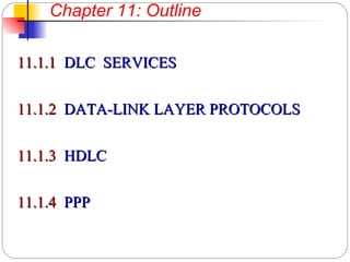
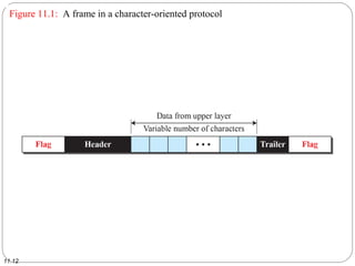
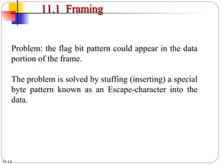
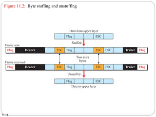
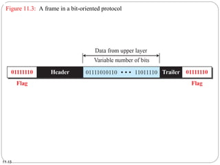
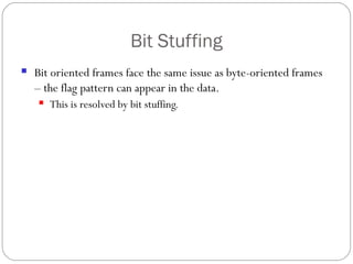
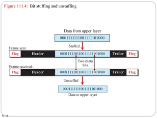
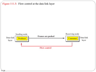
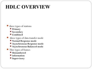
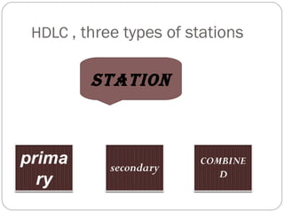
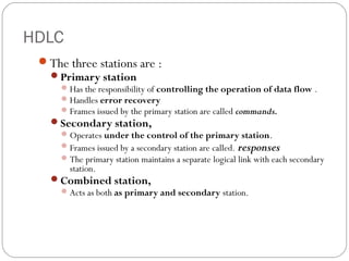
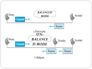
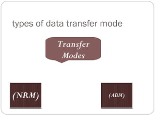
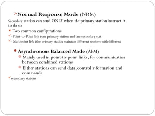
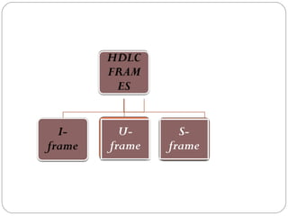
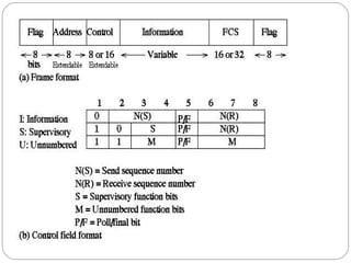
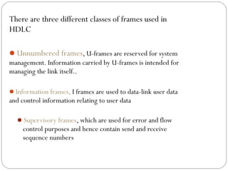
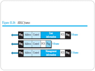
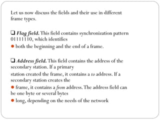
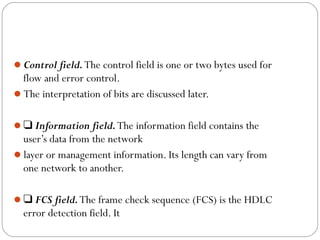
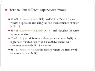
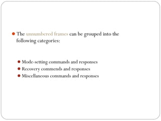
This document provides an overview of data link control (DLC) and data link layer protocols. It discusses the key functions of DLC including framing, flow control, and error control. Framing involves encapsulating data frames with header information like source and destination addresses. Flow control manages the flow of data between nodes while error control handles detecting and correcting errors. Common data link layer protocols described include simple protocol, stop-and-wait protocol, and High-Level Data Link Control (HDLC). HDLC is a bit-oriented protocol that supports full-duplex communication over both point-to-point and multipoint links. It uses three types of frames: unnumbered, information, and supervisory frames.
The data link layer, or layer 2, is the second layer of the seven-layer OSI model of computer networking. This layer is the protocol layer that transfers data between adjacent network nodes in a wide area network (WAN) or between nodes on the same local area network (LAN) segment.
TCP/IP have 5 layers, whereas OSI model have 7 layers in its Model. TCP/IP is known for the secured connection and comunication. I have explained all functions and definitions of layers in TCP/IP Model
INTRODUCTION
WHAT IS OSI?
OSI MODEL
TYPES OF LAYERS
PHYSICAL LAYER
DATA LINK LAYER
NETWORK LAYER
TRANSPORT LAYER
SESSION LAYER
PRESENTATION LAYER
APPLICATION LAYER
Carrier-sense multiple access with collision detection (CSMA/CD) is a media access control method used most notably in early Ethernet technology for local area networking.Carrier-sense multiple access with collision detection is a media access control method used most notably in early Ethernet technology for local area networking. It uses carrier-sensing to defer transmissions until no other stations are transmitting.
The sender initializes the checksum to 0 and adds all data items and the checksum. However, 36 cannot be expressed in 4 bits. The extra two bits are wrapped and added with the sum to create the wrapped sum value 6. The sum is then complemented, resulting in the checksum value 9 (15 − 6 = 9).
Although the OSI reference model is universally recognized, the historical and technical open standard of the Internet is Transmission Control Protocol / Internet Protocol (TCP/IP).
The TCP/IP reference model and the TCP/IP protocol stack make data communication possible between any two computers, anywhere in the world, at nearly the speed of light.
Data Link Layer, Error correction and detection like LRC, VRC, CRC, checksum and Hamming coding, Data link protocols, stop and wait ARQ, sliding window ARQ, Petrinet models, HDLC, etc
How to Split Bills in the Odoo 17 POS ModuleCeline George
Bills have a main role in point of sale procedure. It will help to track sales, handling payments and giving receipts to customers. Bill splitting also has an important role in POS. For example, If some friends come together for dinner and if they want to divide the bill then it is possible by POS bill splitting. This slide will show how to split bills in odoo 17 POS.
How to Make a Field invisible in Odoo 17Celine George
It is possible to hide or invisible some fields in odoo. Commonly using “invisible” attribute in the field definition to invisible the fields. This slide will show how to make a field invisible in odoo 17.
Palestine last event orientationfvgnh .pptxRaedMohamed3
An EFL lesson about the current events in Palestine. It is intended to be for intermediate students who wish to increase their listening skills through a short lesson in power point.
2024.06.01 Introducing a competency framework for languag learning materials ...Sandy Millin
http://sandymillin.wordpress.com/iateflwebinar2024
Published classroom materials form the basis of syllabuses, drive teacher professional development, and have a potentially huge influence on learners, teachers and education systems. All teachers also create their own materials, whether a few sentences on a blackboard, a highly-structured fully-realised online course, or anything in between. Despite this, the knowledge and skills needed to create effective language learning materials are rarely part of teacher training, and are mostly learnt by trial and error.
Knowledge and skills frameworks, generally called competency frameworks, for ELT teachers, trainers and managers have existed for a few years now. However, until I created one for my MA dissertation, there wasn’t one drawing together what we need to know and do to be able to effectively produce language learning materials.
This webinar will introduce you to my framework, highlighting the key competencies I identified from my research. It will also show how anybody involved in language teaching (any language, not just English!), teacher training, managing schools or developing language learning materials can benefit from using the framework.
Unit 8 - Information and Communication Technology (Paper I).pdfThiyagu K
This slides describes the basic concepts of ICT, basics of Email, Emerging Technology and Digital Initiatives in Education. This presentations aligns with the UGC Paper I syllabus.
4. 11.4
11-1 DLC SERVICES11-1 DLC SERVICES
The data link control (DLC) deals with procedures
for communication between two
adjacent nodes.
5. 11.5
11-1 DLC SERVICES11-1 DLC SERVICES
Data link control functions include
● Framing,
● Flow control, and
● Error control
6. 11.6
11.1 Framing (encapsulation)11.1 Framing (encapsulation)
The data-link layer packs bits into frames so that each
frame is distinguishable from another frame.
.
7. 11.7
11.1 Framing11.1 Framing
The postal system practices a type of framing. The
simple act of inserting a letter into an envelope
separates one piece of information from another; the
envelope serves as the delimiter.
8. 11.8
11.1 Framing11.1 Framing
Framing in the data-link layer separates a message by
encapsulating a sender address and a destination
address into a header.
9. 11.9
11.1 Framing11.1 Framing
Framing in the data-link layer separates a message by
encapsulating a sender address and a destination
address into a header.
11. 11.11
11.1 Framing11.1 Framing
Frames may have a particular bit pattern between
frames to help identify the start and end of a frame.
This kind of special bit pattern is referred to as a
“flag”
13. 11.13
11.1 Framing11.1 Framing
Problem: the flag bit pattern could appear in the data
portion of the frame.
The problem is solved by stuffing (inserting) a special
byte pattern known as an Escape-character into the
data.
16. Bit Stuffing
Bit oriented frames face the same issue as byte-oriented frames
– the flag pattern can appear in the data.
This is resolved by bit stuffing.
17. Bit Stuffing
A zero bit is inserted after 5-consecutive one-bits.
21. 11.21
11.2 Flow and Error Control11.2 Flow and Error Control
Error Control involves two methods:
In the first method, if the frame is corrupted, it is
silently discarded; if it is not corrupted, the packet is
delivered to the network layer. This method is used
mostly in wired LANs such as Ethernet.
In the second method, if the frame is corrupted, it is
silently discarded; if it is not corrupted, an
acknowledgment is sent (for the purpose of both flow
and error control) to the sender.
22. Example of flow control:
● A single memory slot is used to hold information for the
receiver node at the data-link layer.
● When this single slot is empty, the data-link layer sends
a request to the sender-node to send the next frame.
Example 111.1
11.22
23. DATA-LINK LAYER PROTOCOLS
Traditionally four protocols have been defined for the data-link layer
to deal with flow and error control: Simple, Stop-and-Wait, Go-Back-
N, and Selective-Repeat.
Although the first two protocols still are used at the data-link layer,
the last two have disappeared.
We therefore briefly discuss the first two protocols in this chapter, in
which we need to understand some wired and wireless LANs.
The behavior of a data-link-layer protocol can be better shown as
24. DATA-LINK LAYER PROTOCOLS
Finite State Machine (FSM)
An FSM is thought of as a machine with a finite number of states.
The machine is always in one of the states until an event occurs.
Each event is associated with two reactions: defining the list
(possibly empty) of actions to be performed and determining the
next state (which can be the same as the current state).
One of the states must be defined as the initial state, the state in
which the machine starts when it turns on. In Figure 11.6, we show
an example of a machine using FSM.
We have used rounded-corner rectangles to show states, colored
text to show events, and regular black text to show actions.
25.
26. Simple Protocol
Simple Protocol
Our first protocol is a simple protocol with neither flow
nor error control.We assume that
the receiver can immediately handle any frame it receives. In
other words, the receiver
can never be overwhelmed with incoming frames. Figure
11.7 shows the layout for this
protocol.
27.
28. FSMs
The sender site should not send a frame until its network layer has a
message to send.
The receiver site cannot deliver a message to its network layer until a
frame arrives.We can show these requirements using two FSMs. Each FSM
has only one state, the ready
state.
The sending machine remains in the ready state until a request comes
from the process in the network layer.
When this event occurs, the sending machine encapsulates
the message in a frame and sends it to the receiving machine.
The receiving machine remains in the ready state until a frame arrives
from the sending machine.
29. Stop and wait:
Sender sends one data frame, waits for acknowledgement
(ACK) from receiver before proceeding to transmit next frame –
This simple flow control will break down if ACK gets lost or
errors occur sender may wait for ACK that never arrives→
30.
31.
32. Sender States
The sender is initially in the ready state, but it can move between the ready and blocking state
.Ready State.When the sender is in this state, it is only waiting for a packet from the network layer.
If a packet comes from the network layer, the sender creates a frame, saves a copy of the frame,
starts the only timer and sends the frame.The sender then moves to the blocking state.
Blocking State.When the sender is in this state, three events can occur:
a. If a time-out occurs, the sender resends the saved copy of the frame and restarts the timer.
b. If a corrupted ACK arrives, it is discarded.
c. If an error-free ACK arrives, the sender stops the timer and discards the saved copy of the frame.
It then moves to the ready state.
Receiver
The receiver is always in the ready state.Two events may occur:
a. If an error-free frame arrives, the message in the frame is delivered to the network layer and an
ACK is sent.
b. If a corrupted frame arrives, the frame is discarded.
33. Piggybacking
Piggybacking
The two protocols we discussed in this section are designed for unidirectional
communication, in which data is flowing only in one direction although the
acknowledgment may travel in the other direction.
Protocols have been designed in the past to allow data
to flow in both directions. However, to make the communication more
efficient, the data in one direction is piggybacked with the acknowledgment in
the other direction.
In other words, when nodeA is sending data to node B, Node A also
acknowledges the data received from node B. Because piggybacking makes
communication at the data link layer more complicated, it is not a common
practice.
34. WHAT IS HDLC….?
High-level Data Link Control (HDLC) is a
bit- oriented protocol i.e use bits to stuff
flags occurring in data.
HDLC was defined by ISO for use on both
point-to-point and multipoint data links.
It supports full-duplex communication i.e
receive and transmit at the same time.
35. HDLC OVERVIEW
three types of stations
Primary
Secondary
Combined
three types of data transfer mode
Normal Response mode
Asynchronous Response mode
Asynchronous Balanced mode
Thre types of frames
Unnumbered
information
Supervisory
37. HDLC
The three stations are :
Primary station
Has the responsibility of controlling the operation of data flow .
Handles error recovery
Frames issued by the primary station are called commands.
Secondary station,
Operates under the control of the primary station.
Frames issued by a secondary station are called. responses
The primary station maintains a separate logical link with each secondary
station.
Combined station,
Acts as both as primary and secondary station.
40. Normal Response Mode (NRM)
Secondary station can send ONLY when the primary station instruct it
to do so
Two common configurations
- Point-to-Point link (one primary station and one secondary stat
- Multipoint link (the primary station maintain different sessions with different
Asynchronous Balanced Mode (ABM)
Mainly used in point-to-point links, for communication
between combined stations
Either stations can send data, control information and
commands
secondary stations
41.
42.
43. There are three different classes of frames used in
HDLC
Unnumbered frames, U-frames are reserved for system
management. Information carried by U-frames is intended for
managing the link itself..
Information frames, I frames are used to data-link user data
and control information relating to user data
Supervisory frames, which are used for error and flow
control purposes and hence contain send and receive
sequence numbers
44.
45. Let us now discuss the fields and their use in different
frame types.
❑ Flag field.This field contains synchronization pattern
01111110, which identifies
both the beginning and the end of a frame.
❑ Address field.This field contains the address of the
secondary station. If a primary
station created the frame, it contains a to address. If a
secondary station creates the
frame, it contains a from address.The address field can
be one byte or several bytes
long, depending on the needs of the network
46. Control field.The control field is one or two bytes used for
flow and error control.
The interpretation of bits are discussed later.
❑ Information field.The information field contains the
user’s data from the network
layer or management information. Its length can vary from
one network to another.
❑ FCS field.The frame check sequence (FCS) is the HDLC
error detection field. It
47. There are four different supervisory frames
SS=00, Receiver Ready (RR), and N(R)ACKs all frames
received up to and including the one with sequence number
N(R) - 1
SS=10, Receiver Not Ready (RNR), and N(R) has the same
meaning as above
SS=01, Reject; all frames with sequence number N(R) or
higher are rejected, which in turns ACKs frames with
sequence number N(R) -1 or lower.
SS=11, Selective Reject; the receive rejects the frame with
sequence number N(R)
48. The unnumbered frames can be grouped into the
following categories:
Mode-setting commands and responses
Recovery commends and responses
Miscellaneous commands and responses