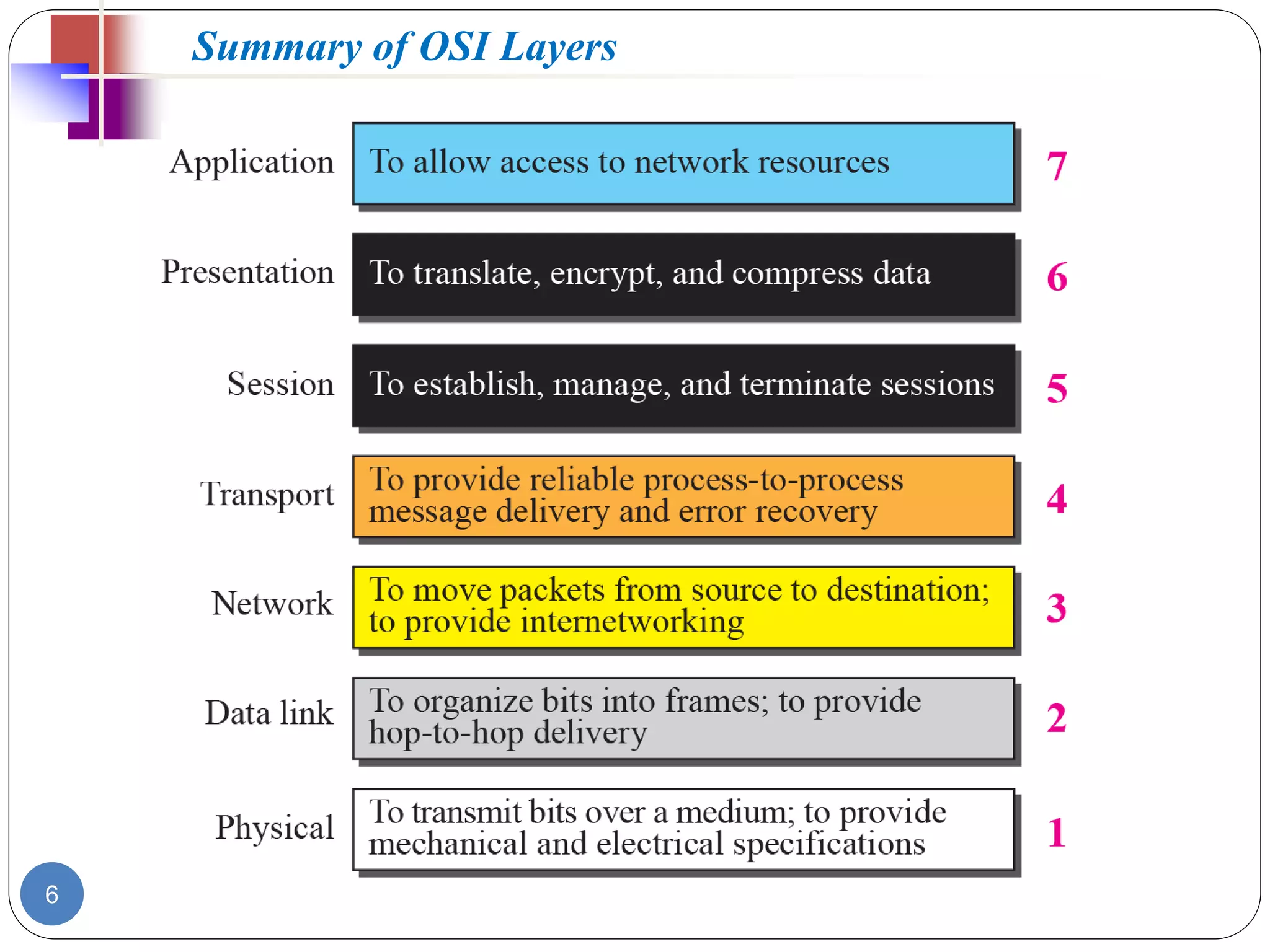
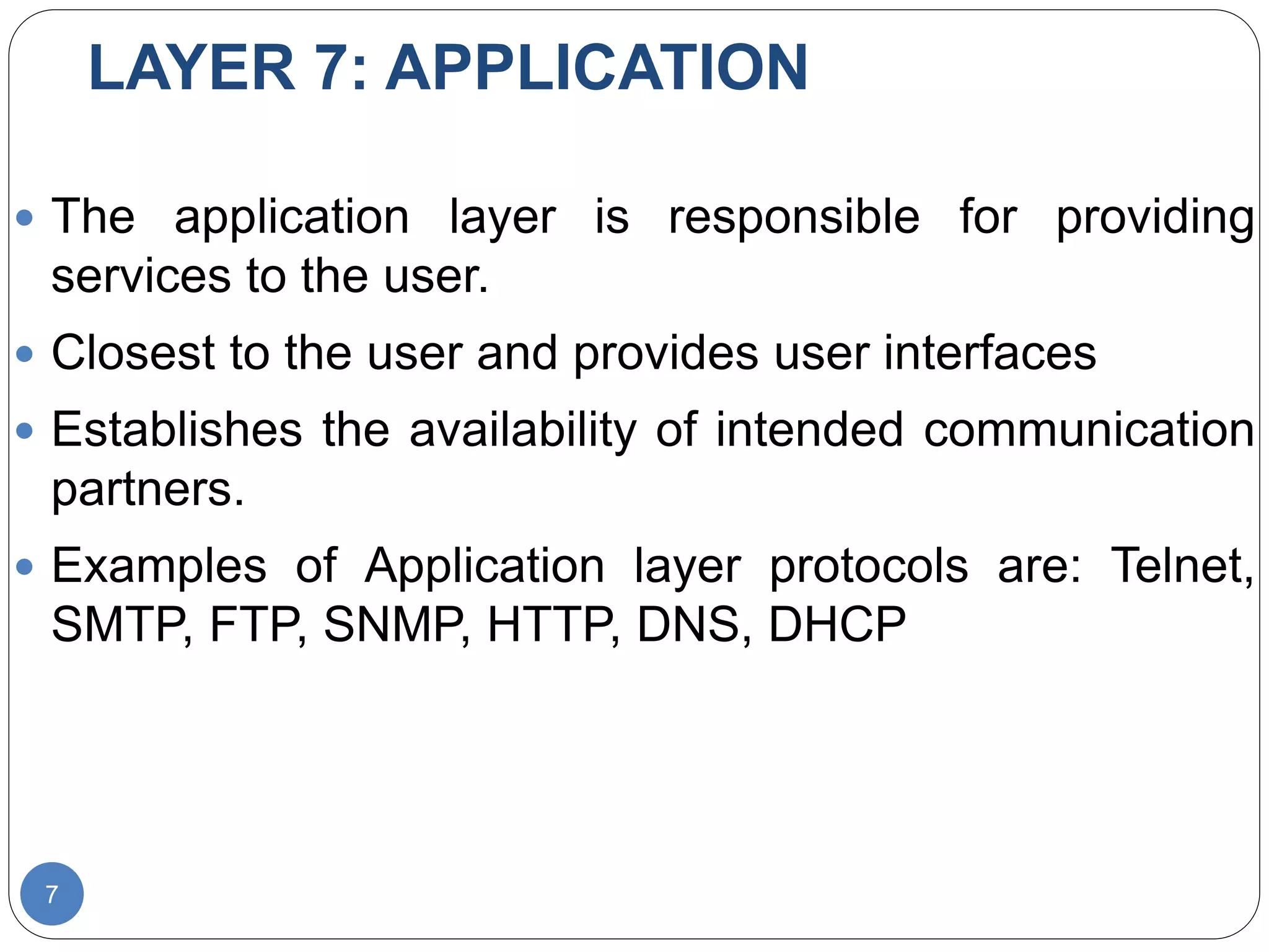
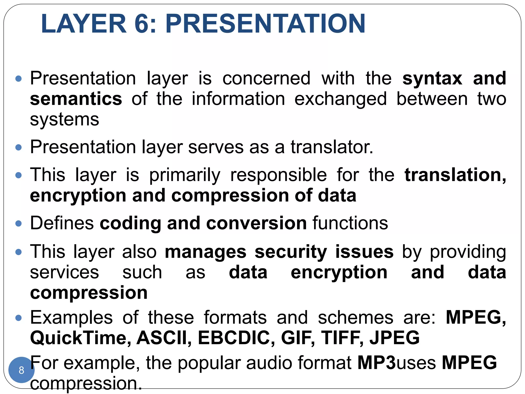
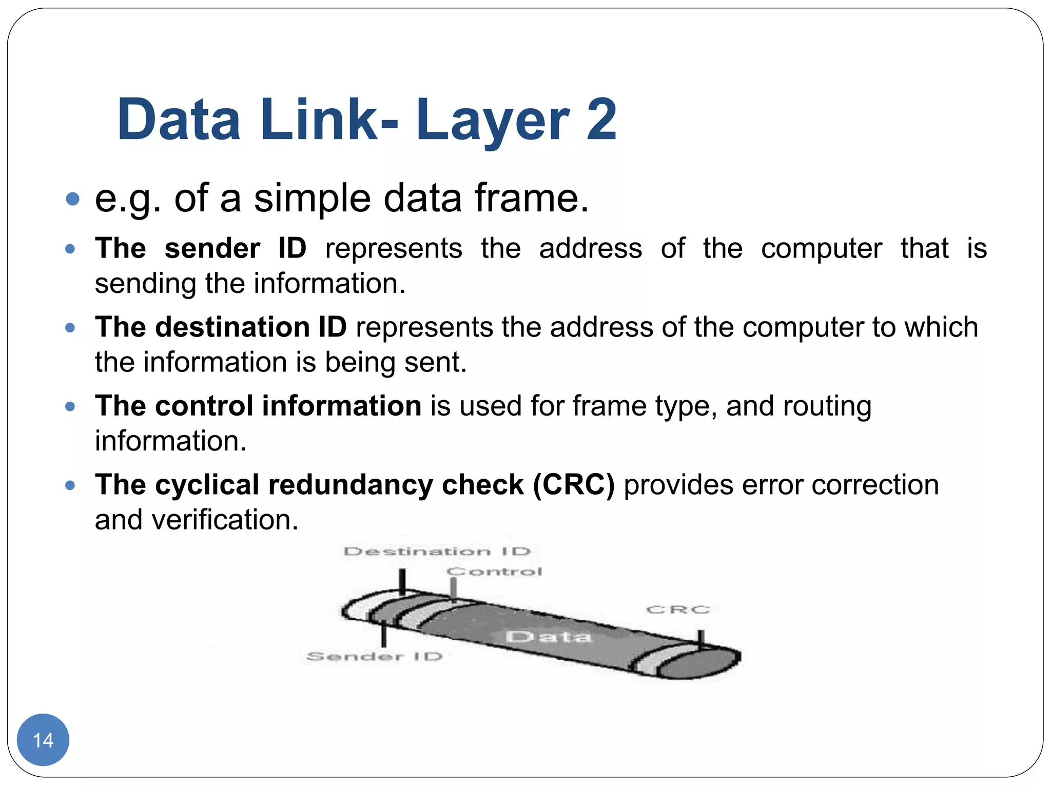
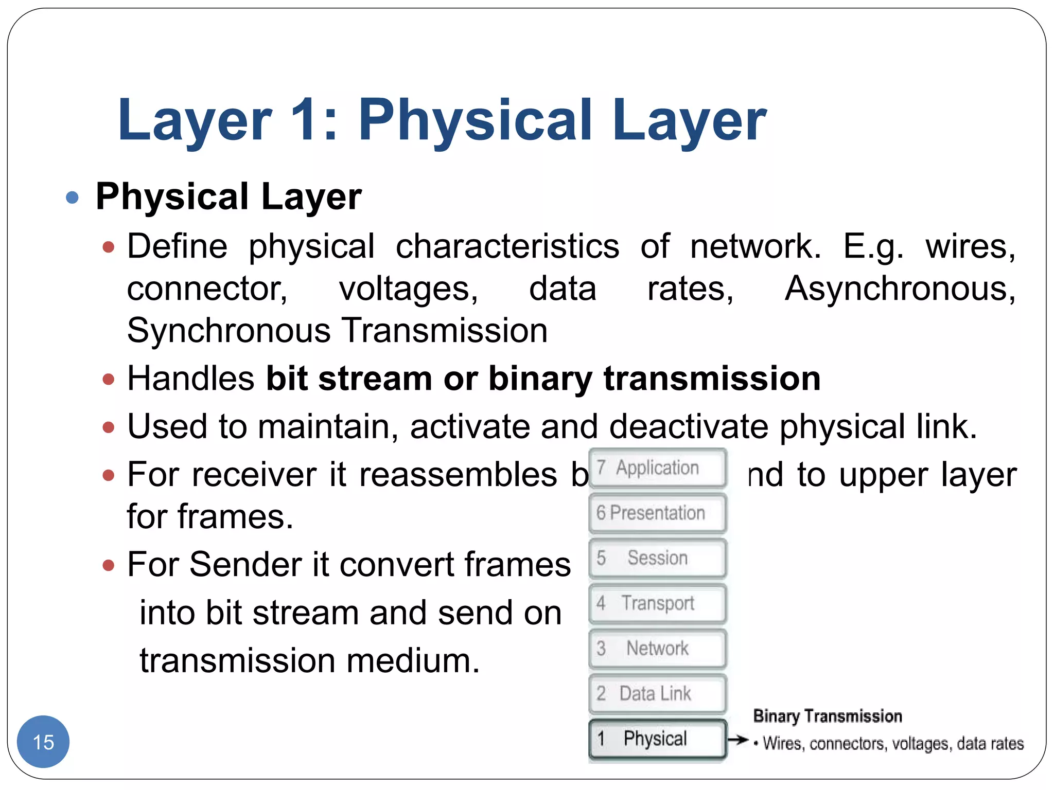
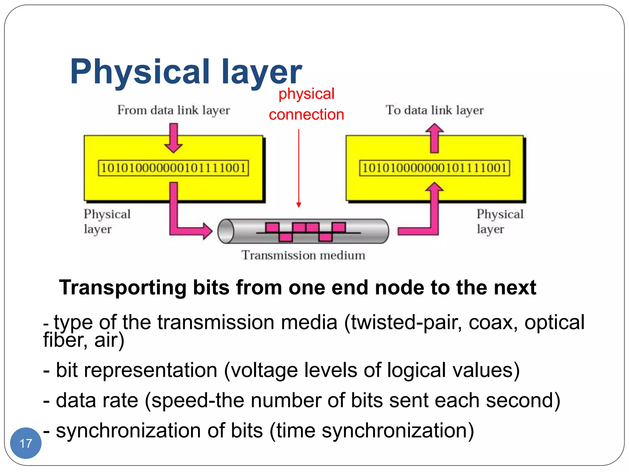
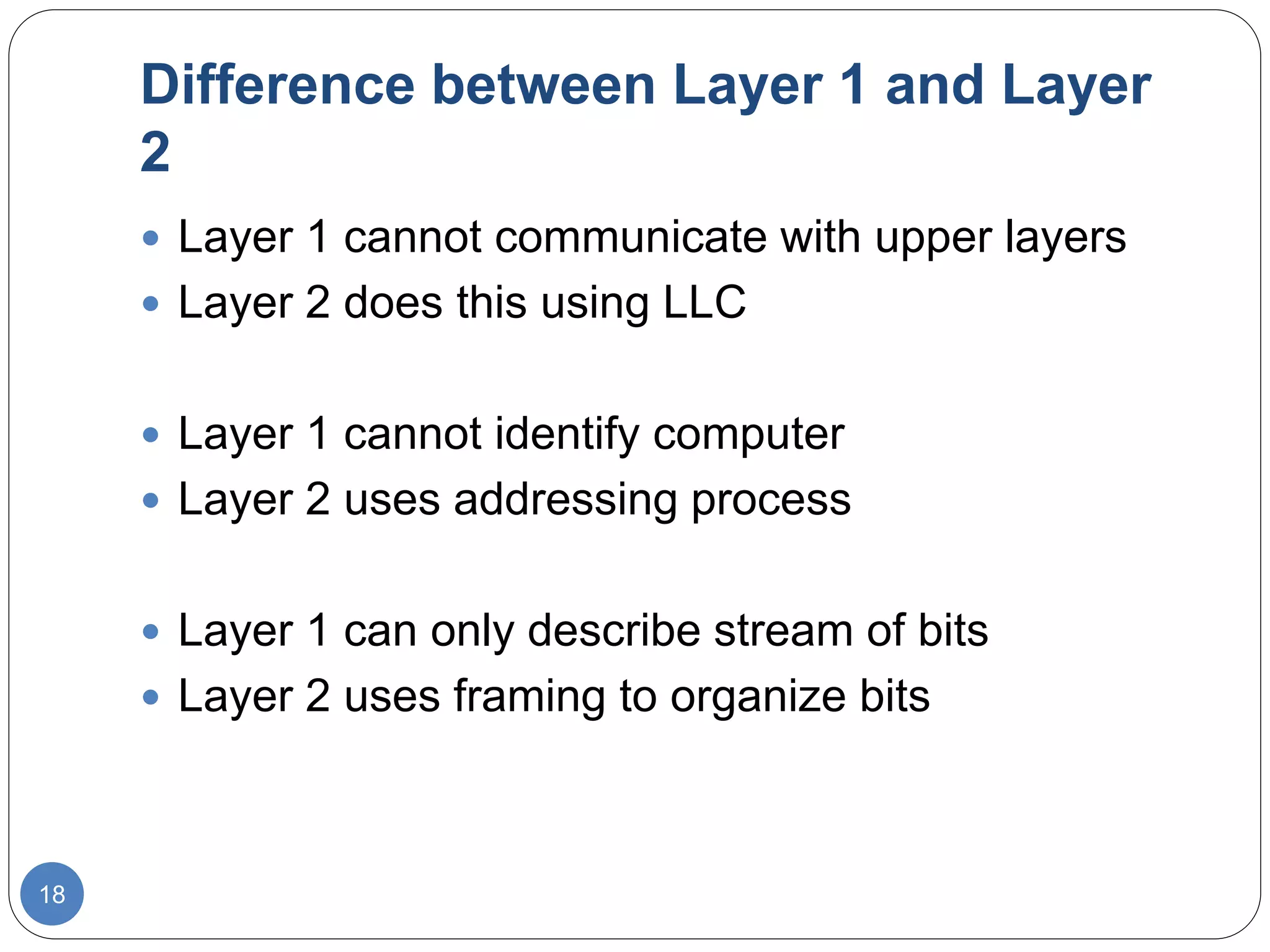
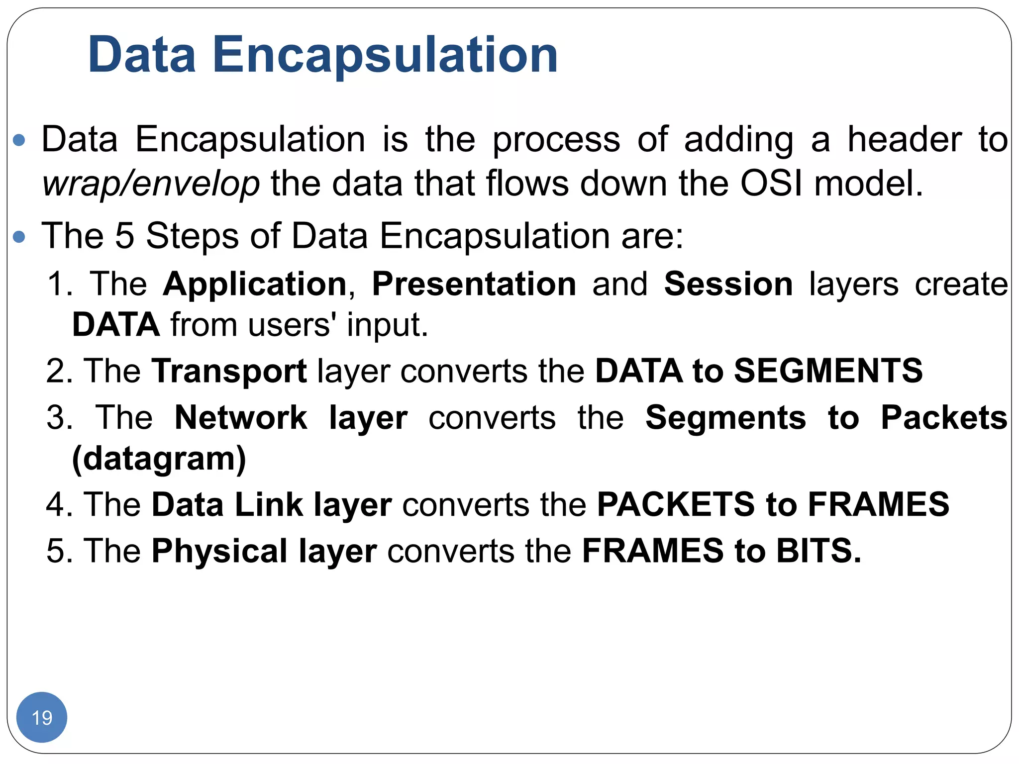
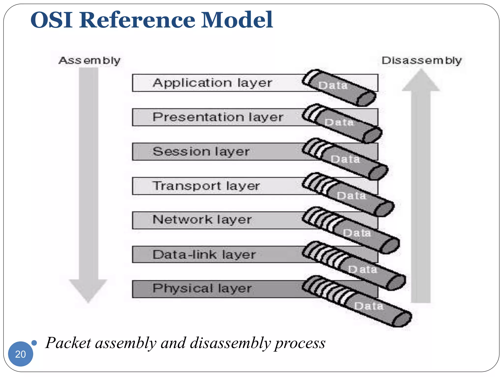
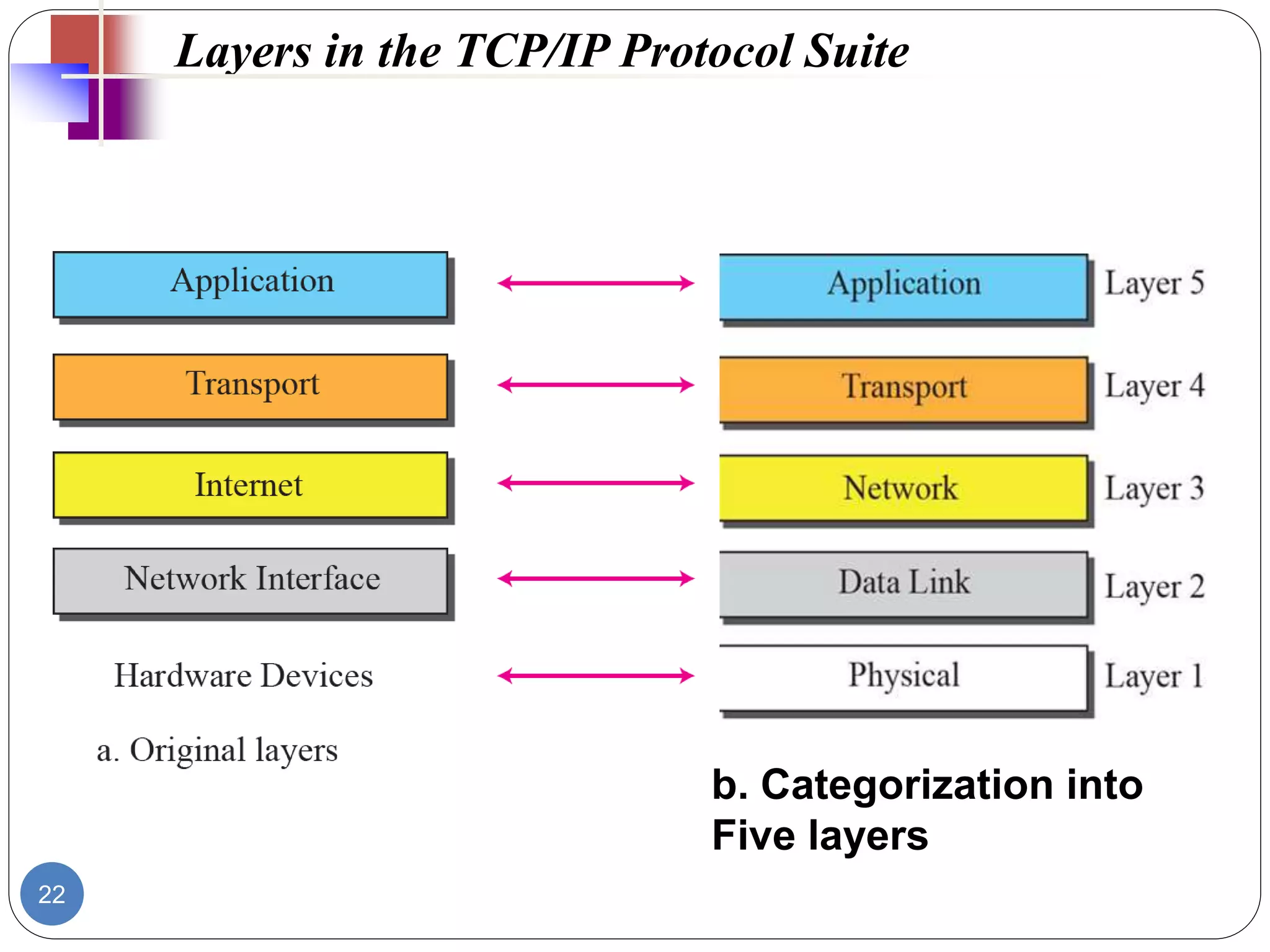
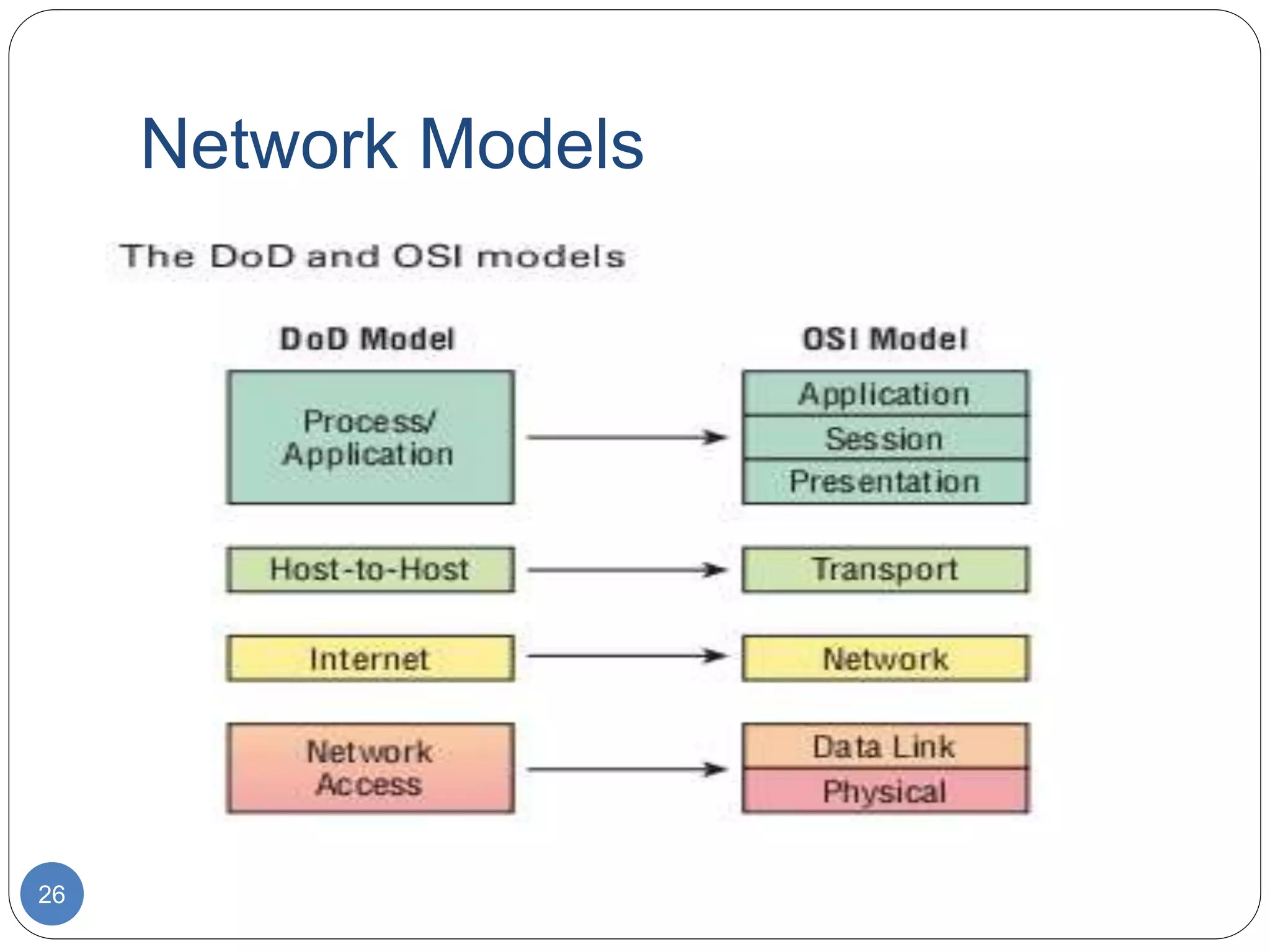
2. Network Models
2
Computer networks are created by different
entities.
Standards are needed so that these
heterogeneous networks can communicate
with one another.
The two best-known standards are the OSI
model and the TCP/IP model.
Protocols are sets of instructions designed
and coded by programmers.
3. The OSI Model
3
It was developed by the International
Organization for Standardization (ISO).
It is a model for a computer protocol
architecture and as a framework for
developing protocol standards.
An ISO standard that covers all aspects of
network communications is the Open Systems
Interconnection (OSI) model.
Comprises of seven layers
4. Advantages of OSI
4
Network communication is broken into
smaller, more manageable parts.
Allows different types of network hardware
and software to communicate with each
other.
All layers are independent and changes does
not affect other layers.
Easier to understand network
communication.
5. Why layered communication?
5
To reduce complexity of communication task by
splitting it into several layered small tasks
• assists in protocol design
• foster competition
• changes in one layer do not affect other layers
• provides a common language
7. LAYER 7: APPLICATION
7
The application layer is responsible for providing
services to the user.
Closest to the user and provides user interfaces
Establishes the availability of intended communication
partners.
Examples of Application layer protocols are: Telnet,
SMTP, FTP, SNMP, HTTP, DNS, DHCP
8. LAYER 6: PRESENTATION
8
Presentation layer is concerned with the syntax and
semantics of the information exchanged between two
systems
Presentation layer serves as a translator.
This layer is primarily responsible for the translation,
encryption and compression of data
Defines coding and conversion functions
This layer also manages security issues by providing
services such as data encryption and data
compression
Examples of these formats and schemes are: MPEG,
QuickTime, ASCII, EBCDIC, GIF, TIFF, JPEG
For example, the popular audio format MP3uses MPEG
compression.
9. LAYER 5: SESSION
9
The session layer defines how to start, control and end
conversations (called sessions) between applications
Establishes dialog control between the two computers
in a session, regulating which side transmits, plus when
and how long it transmits (Full duplex)
Synchronization: Allows processes to add check points.
E.g. Insert check point at every 100 pages of 2000 pages
file to ensure that each 100-page unit is received &
acknowledged.
10. LAYER 4: TRANSPORT
10
It regulates information flow to ensure process-to- process
connectivity between host applications reliably and accurately
Adds service point address or Port address
Segmentation & Re-assembly: SEGMENTS data from
sending node and reassembles data on receiving node
Flow control / Error control at Source to destination level
Connection oriented transport service ensures that data is
delivered error free, in sequence with no losses or
duplications
Establishes, maintains and terminates virtual circuits
Connection oriented / Connectionless:
-TCP (Reliable, provides guaranteed delivery),
-UDP (Unreliable, less overhead, reliability can be
provided by
the Application layer)
Provides multiplexing: the support of different flows of data to
11. LAYER 3: NETWORK
11
Defines source to destination delivery of packets across
NWs
Defines logical addressing and best path
determination.
Treat each packet independently
Defines how routing works and how routes are learned
Converts frames to packets
Routed protocols ( encapsulate data into packets) and
Routing protocols (create routing tables) work on this layer
Examples of Routed protocols are: IP, IPX, AppleTalk and
Routing protocols are OSPF, IGRP/EIGRP, RIP, BGP
Routers operate at Layer 3.
12. LAYER 2: DATA LINK
12
Packages raw bits from the physical layer into FRAMES
The data link layer provides reliable transit of data across a
physical link by using the Media Access Control (MAC)
addresses
Source & Destination ( address of device that connects one
Network to next) address
Flow Control: refers to a set of procedures used to restrict the
amount of data that the sender can send before receiving an
acknowledgement
Error Control: refers to both error detection and error
correction
Data Link LAN specifications: Fast Ethernet, Token Ring,
FDDI .
Data Link WAN specifications are: Frame Relay, PPP,
13. Sub layers of Layer 2
13
Logical link layer (LLC)
Used for communication with upper layers
Error correction
Flow control
Media Access Control (MAC)
Access to physical medium
Frames include information about:
Which computers are in communication with each
other
When communication between individual computers
begins and when it ends
Which errors occurred while the computers
communicated (LLC)
14. Data Link- Layer 2
14
e.g. of a simple data frame.
The sender ID represents the address of the computer that is
sending the information.
The destination ID represents the address of the computer to which
the information is being sent.
The control information is used for frame type, and routing
information.
The cyclical redundancy check (CRC) provides error correction
and verification.
15. Layer 1: Physical Layer
15
Physical Layer
Define physical characteristics of network. E.g. wires,
connector, voltages, data rates, Asynchronous,
Synchronous Transmission
Handles bit stream or binary transmission
Used to maintain, activate and deactivate physical link.
For receiver it reassembles bits and send to upper layer
for frames.
For Sender it convert frames
into bit stream and send on
transmission medium.
16. Properties of Physical Layers
16
Deals with bit stream.
Transmits raw bit stream over physical cable
defines cables, cards, and physical aspects
defines NIC attachments to hardware, how cable
is attached to NIC
defines techniques to transfer bit stream to cable
Layer 1 Device: Repeater, Hub, Multiplexer
17. Physical layer
17
Transporting bits from one end node to the next
- type of the transmission media (twisted-pair, coax, optical
fiber, air)
- bit representation (voltage levels of logical values)
- data rate (speed-the number of bits sent each second)
- synchronization of bits (time synchronization)
physical
connection
18. Difference between Layer 1 and Layer
2
18
Layer 1 cannot communicate with upper layers
Layer 2 does this using LLC
Layer 1 cannot identify computer
Layer 2 uses addressing process
Layer 1 can only describe stream of bits
Layer 2 uses framing to organize bits
19. Data Encapsulation
19
Data Encapsulation is the process of adding a header to
wrap/envelop the data that flows down the OSI model.
The 5 Steps of Data Encapsulation are:
1. The Application, Presentation and Session layers create
DATA from users' input.
2. The Transport layer converts the DATA to SEGMENTS
3. The Network layer converts the Segments to Packets
(datagram)
4. The Data Link layer converts the PACKETS to FRAMES
5. The Physical layer converts the FRAMES to BITS.
21. 21
TCP/IP PROTOCOL SUITE
By IETF: The Internet Engineering Task Force/DoD
(Department of Defense)
The TCP/IP protocol suite was developed prior to the OSI
model.
Therefore, the layers in the TCP/IP protocol suite do not
match exactly with those in the OSI model.
The original TCP/IP protocol suite was defined as four
software layers built upon the hardware.
Today, however, TCP/IP is thought of as a five-layer model
with the layers named similarly to the ones in the OSI model.
22. 22
Layers in the TCP/IP Protocol Suite
b. Categorization into
Five layers
23. The key features of a protocol
23
In the context of data networking, a protocol is a formal
set of rules and conventions that governs how
computers exchange information over a network medium.
The peer layers communicate by means of formatted blocks of
data that obey a set of rules or conventions known as a
protocol. The key features of protocol are:
Syntax – Syntax.-refers to the structure or format of the
data, meaning the order in which they are presented.
Semantics - control info. & error handling
Timing - speed matching & sequencing-decides when
data should be sent and how fast they can be sent.
24. OSI and TCP/IP similarities
24
Similarities include:
Both have layers.
Both have application layers, though they include very different
services.
Both have comparable transport and network layers.
Both assume packets are switched. This means that individual
packets may take different paths to reach the same destination.
This is contrasted with circuit-switched networks where all the
packets take the same path.
25. OSI and TCP/IP Differences
25
Differences include:
TCP/IP combines the presentation and session layer issues into
its application layer.
TCP/IP combines the OSI data link and physical layers into the
network access layer.
TCP/IP appears simpler because it has fewer layers.
TCP/IP protocols are the standards around which the Internet
developed, so the TCP/IP model gains credibility just because of its
protocols.
In contrast, networks are not usually built on the OSI protocol,
even though the OSI model is used as a guide.
27. TCP/IP Process/Application
layer
27
These process integrate the various activities and
duties spanning the focus of the OSI’s corresponding
top three layers (Application, Presentation, and
Session).
Controls user-interface specifications.
28. TCP/IP Host-to-Host/Transport
layer
28
The Host-to-Host layer parallels the functions of the
OSI’s Transport layer, defining protocols for setting up
the level of transmission service for applications.
It tackles issues like creating reliable end-to-end
communication and ensuring the error-free delivery of
data.
It handles packet sequencing and maintains data
integrity.
29. TCP/IP INTERNET LAYER
29
The Internet layer corresponds to the OSI’s
Network layer, designating the protocols relating
to the logical transmission of packets over the
entire network.
It takes care of the addressing of hosts by giving
them an IP (Internet Protocol) address and
handles the routing of packets among multiple
networks.
30. TCP/IP NETWORK ACCESS
LAYER
30
At the bottom of the DoD model, the Network Access
layer implements the data exchange between the host
and the network.
The equivalent of the Data Link and Physical layers
of the OSI model, the Network Access layer oversees
hardware addressing and defines protocols for the
physical transmission of data.
The reason TCP/IP became so popular is because
there were no set physical layer specifications, so it
could run on any existing or future physical network!
33. Application layer protocol- Simple Mail
Transfer Protocol (SMTP)
33
Governs the transmission of mail messages and
attachments
SMTP is used in the case of outgoing messages
More powerful protocols such as POP3 and IMAP4 are
needed and available to manage incoming messages
POP3(Post Office Protocol version 3) is the older
protocol
IMAP4(Internet Mail Access Protocol version 4) is
the more advanced protocol
34. Application layer protocol-
Telnet
34
Telnet is a protocol used to log on to remote hosts
using the TCP/IP protocol suite.
Using Telnet, a TCP connection is established and
keystrokes on the user’s machine act like keystrokes
on the remotely connected machine.
Often, Telnet is used to connect two dissimilar
systems (such as PCs and UNIX machines).
Through Telnet, you can control a remote host over
LANs and WANs such as the Internet.
For example, network managers can use Telnet to
log on to a router from a computer elsewhere on their
LAN and modify the router’s configuration.
35. Application layer protocol- File Transfer
Protocol (FTP)
35
File Transfer Protocol (FTP) lets us transfer files, and it
can accomplish this between any two machines using
it.
But accessing a host through FTP is only the first step.
Users must then be subjected to an authentication
login that’s usually secured with passwords and
usernames implemented by system administrators to
restrict access.
FTP’s functions are limited to listing and manipulating
directories, typing file contents, and copying files
between hosts.
38. Trivial File Transfer Protocol (TFTP)
38
Trivial File Transfer Protocol (TFTP) is stock version of
FTP, but it’s the protocol of choice if you know exactly
what you want and where to find it because it’s fast
and so easy to use!
But TFTP doesn’t offer the abundance of functions
that FTP does because it has no directory-browsing
abilities, meaning that it can only send and receive
files
There’s no authentication as with FTP, so it’s even
more insecure, and few sites support it because of
the inherent security risks.
A significant difference between FTP and TFTP is that
TFTP relies on UDP at the Transport layer, but FTP
39. Simple Network Management Protocol
(SNMP)
39
Simple Network Management Protocol (SNMP) collects
and manipulates valuable network information.
It gathers data from a network management station
(NMS) at fixed or random intervals, requiring them to
disclose certain information, or even asking for
certain information from the device.
In addition, network devices can inform the NMS
about problems as they occur so the network
administrator is alerted.
41. Hypertext Transfer Protocol (HTTP)
41
It’s used to manage communications between web
browsers and web servers and opens the right
resource when you click a link, wherever that
resource may actually reside.
In order for a browser to display a web page, it must
find the exact server that has the right web page, plus
the exact details that identify the information
requested.
The browser can understand what you need when you
enter a Uniform Resource Locator (URL), which we
usually refer to as a web address, e.g.
http://www.lammle.com/forum and
http://www.lammle.com/blog.
Each URL defines the protocol used to transfer data,
43. Hypertext Transfer Protocol Secure
(HTTPS)
43
Hypertext Transfer Protocol Secure (HTTPS) is also
known as Secure Hypertext Transfer Protocol.
It uses Secure Sockets Layer (SSL).
Sometimes you’ll see it referred to as SHTTP or S-
HTTP, which were slightly different protocols, but since
Microsoft supported HTTPS, it became the de facto
standard for securing web communication.
But no matter-as indicated, it’s a secure version of
HTTP that arms you with a whole bunch of security
tools for keeping transactions between a web
browser and a server secure.
44. Domain Name Service (DNS)
44
The Domain Name System (DNS) is a directory
lookup service that provides a mapping between
the name of a host on the Internet and its
numerical address.
Domain Name Service (DNS)-resolves
hostnames- to IP addresses specifically, Internet
names, such as www.au.edu.et
But you don’t have to actually use DNS. You just
type in the IP address of any device you want to
communicate with and find the IP address of a
URL by using the Ping program.
For example, >ping www.cisco.com will return the
IP address resolved by DNS.
45. Domain Name System (DNS)
45
Resolves domain names to IP addresses and
vice versa
•An IP address identifies hosts on a network and
the Internet as well, but DNS was designed to
make our lives easier.
•The IP address would change and no one
would know what the new one was.
•DNS allows you to use a domain name to specify
an IP address. DNS Server 10.1.0.15
www.amu.edu.et
46. Domain Name
46
A domain name is represented by a series of
character strings, called labels, separated by
dots.
Each label represents a level in the domain
naming hierarchy.
E.g In the domain name www.google.com,
com is the top-level domain (TLD), google is
the second-level domain, and www is the third-
level domain.
Each second-level domain can contain multiple
third level domains.
E.g In addition to www.google.com, Google
47. DNS cont’d…
15-47
The very last section of the domain is called its
top-level domain (TLD) name
Top-level domains, including some relatively new ones
49. Dynamic Host Configuration Protocol
(DHCP)
49
Dynamic Host Configuration Protocol (DHCP) assigns
IP addresses to hosts dynamically.
It allows for easier administration and works well in
small to very large network environments.
Many types of hardware can be used as a DHCP
server, including a Cisco router.
A DHCP address conflict occurs when two hosts
use the same IP address. This sounds bad, and it
is!
50. 50
A lot of information a DHCP server can provide to a
host when the host is requesting an IP address from
the DHCP server.
Here’s a list of the most common types of
information a DHCP server can provide:
IP address
Subnet mask
Domain name
Default gateway (routers)
DNS server address
51. 51
This is the four-step process a client takes to receive
an IP address from a DHCP server:
1. The DHCP client broadcasts a DHCP Discover
message looking for a DHCP server (Port 67).
2. The DHCP server that received the DHCP Discover
message sends a layer 2 unicast DHCP Offer
message back to the host.
3. The client then broadcasts to the server a DHCP
Request message asking for the offered IP address
and possibly other information.
4. The server finalizes the exchange with a unicast
DHCP Acknowledgment message.
Etc….
53. TCP(Transmission Control
Protocol)
53
TCP: takes large blocks of information from an
application and breaks them into segments.
It numbers and sequences each segment to keep
the order the application intended.
After these segments are sent on the transmitting
host, TCP waits for an acknowledgment of the
receiving end’s.
Retransmitting any segments that aren’t
acknowledged.
It is Connection oriented means that a virtual
connection is established before any user data is
54. TCP cont’d..
54
TCP can also recognize duplicate messages and
will discard them appropriately.
If the sending computer is transmitting too fast for
the receiving computer, TCP can employ flow
control mechanisms to slow data transfer.
TCP can also communicates delivery information to
the upper-layer protocols and applications it
supports.
All these characteristics makes TCP an end-to-end
reliable transport protocol.
56. Some of fields in TCP segment
56
Source port : This is the port number of the application
on the host sending the data.
Destination port: This is the port number of the
application requested on the destination host.
Sequence number: A number used by TCP that puts
the data back in the correct order or retransmits
missing or damaged data during a process called
sequencing.
Acknowledgment number: The value is the TCP
octet that is expected next.
57. Cont’d…
57
Header length: The number of 32-bit words in the TCP
header, which indicates where the data begins.
Reserved: for future use, Always set to zero.
Code bits/flags: Controls functions used to set up and
terminate a session.
-it used to determine segment purpose, e.g. SYN, ACK
Window: is window size the sender willing to accept, in
octets.
Checksum: The cyclic redundancy check (CRC), used
because TCP doesn’t trust the lower layers and checks
everything.
The CRC checks the header and data fields
-TCP keeps check that if bytes are damaged, through
checksum.
Etc….
58. User Datagram Protocol (UDP)
58
User Datagram Protocol (UDP) is basically the scaled-
down economy model of TCP, which is why UDP is
sometimes referred to as a thin protocol.
Like a thin person , a thin protocol doesn’t take up a lot
of room—or in this case, require much bandwidth on
a network.
UDP does not sequence the segments and does not
care about the order in which the segments arrive at
the destination.
UDP just sends the segments off and forgets about
them.
59. UDP cont’d…
59
It doesn’t follow segments, check up on them, or
even allow for an acknowledgment of safe arrival.
Because of this, it’s referred to as an unreliable
protocol.
This does not mean that UDP is ineffective, only
that it doesn’t deal with reliability issues at all.
Furthermore, UDP doesn’t create a virtual circuit or
doesn’t contact the destination before delivering
information to it.
- Because of this, it’s also considered a connectionless
protocol.
60. UDP cont’d…
60
NOTE:
Since UDP assumes that the application will use
its own reliability method, it doesn’t use any
itself.
This presents an application developer with a
choice when running the Internet Protocol stack:
TCP for reliability or UDP for faster transfers.
TCP sequences the segments so they get put
back together in exactly the right order, which is
something UDP just can’t do.
61. UDP in short
61
Minimum overhead.
Used to send short messages.
Not reliable as TCP (out of order, missing datagram,
duplicate datagram).
Lack of flow control and error control
Faster and efficient
Communication takes place using ports.
Header contains following information:
Source port number (16 bits)
Destination port number (16 bits)
Total length(16 bits)
checksum(16 bits)
65. Internet Protocol (IP) (Layer 3
protocol)
65
Used for data communication in packet switched
network
Unreliable and connectionless (no specific path)
Unreliable
Data corruption
Packet lost
Out of order
Packet called Datagram
Internetworking computers
Internet Protocol versions: IPv4, IPv6
67. Cont’d…
67
Source & destination IP address (32 bits each):
contain IP address of sender and intended recipient.
Options (variable length): Mainly used to record a route,
or timestamps, or specify routing.
Identification: copied into fragment, allows
destination to know which fragments belong to
which datagram
Fragment Offset (12 bits): specifies the offset in the
original datagram of the data being carried in the
fragment
Measured in units of 8 bytes starting at 0
Flags (3 bits): control fragmentation
68. ARP Protocol (layer 3)
68
Stands for address resolution protocol
Finding physical address from logical address
Host or router transmit IP datagram packet
containing logical address obtained from DNS.
Query is broadcast but reply is uncast.
Request contains sender and receiver IP plus
sender physical address.
Reply contains physical address of the receiver.
69. Cont’d…
69
Reverse of ARP=RARP
Finding logical address from physical address
Request broadcast to network reply is uncast.
Based on client/server protocol.
71. ICMP (Internet Control Message Protocol)(Layer
3)
71
Used to report errors with delivery of IP data.
E.g. if particular service or host not reachable or to
check routers are correctly routing .
Ping tool uses ICMP to check host is reachable and
how long it takes to reach.
ICMP message is delivered in IP packet.
Error reporting not error correction.
Two types of messages
Error reporting message
Problems with router or host e.g. destination unreachable, time
exceeded, parameters problem
Query message
Help in getting specific information. e.g. neighbors
72. ICMP Errors
72
Network Errors:
Host or network unreachable
Network congestion message:
When router buffers too many packets, and
don’t process with same speed as received,
generates source quench message. Too many
messages results congestion.
Time exceed
ICMP timeout message is generated when host
is unreachable.
73. IGMP Layer 3
73
Internet Group Management Protocol
IGMP-is used to facilitate the simultaneous
transmission of a message to a group of
recipients.
Protocol that manages group membership.
Provides information to multicast routers
about the membership status of hosts.
Routers use IGMP to determine which hosts
belong to a multicast group
Hosts use IGMP to join or leave a multicast
group.