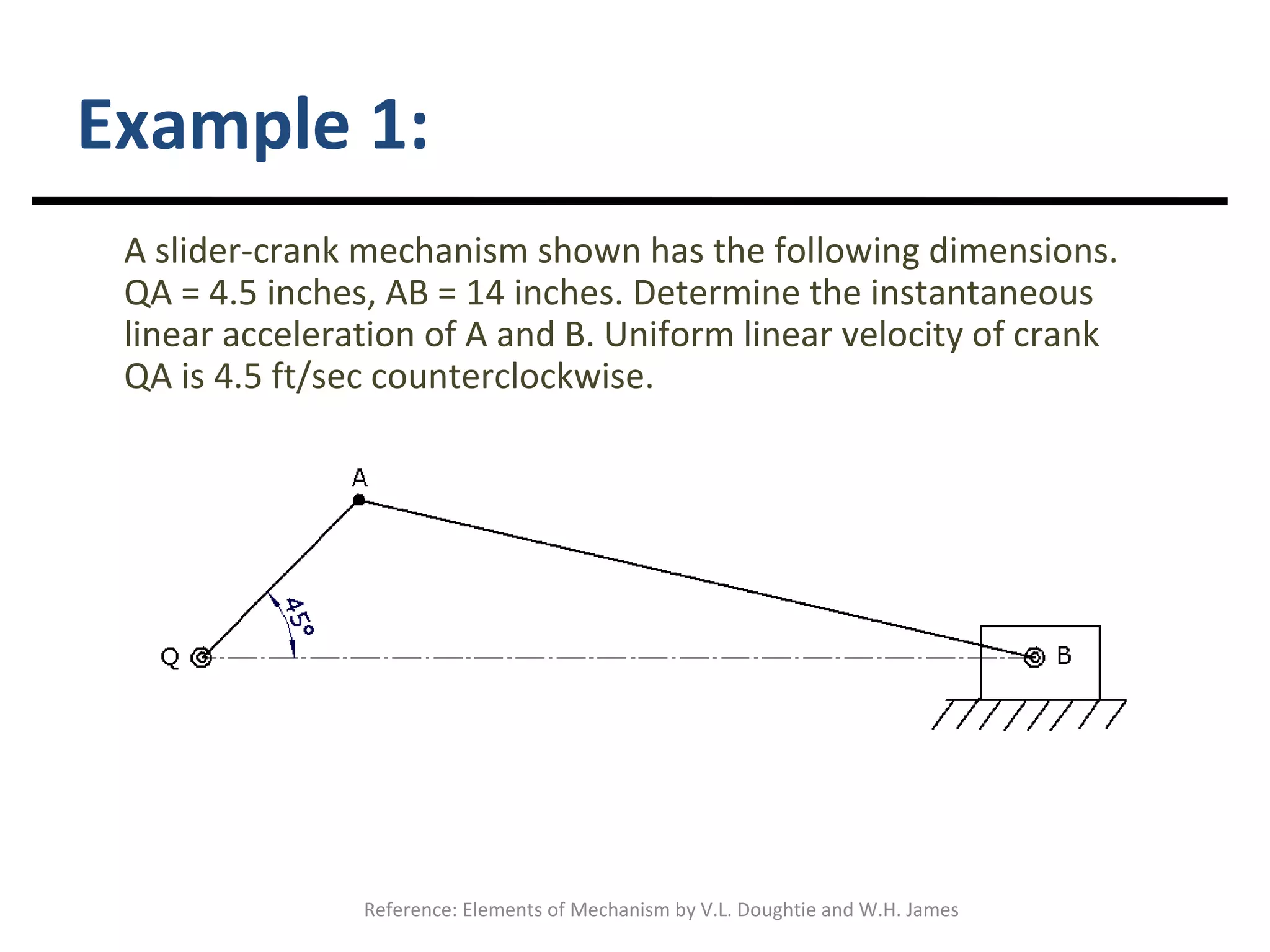
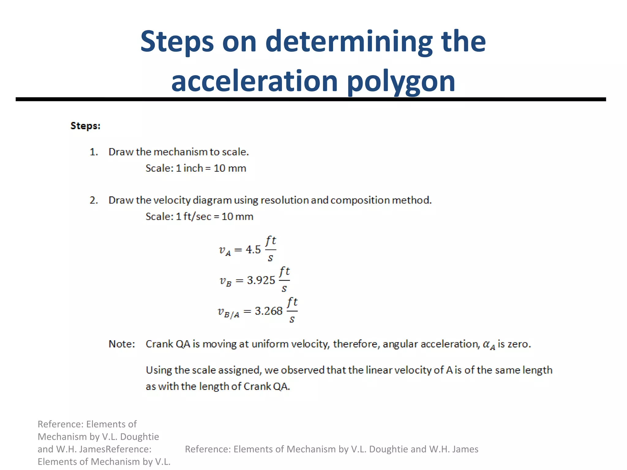
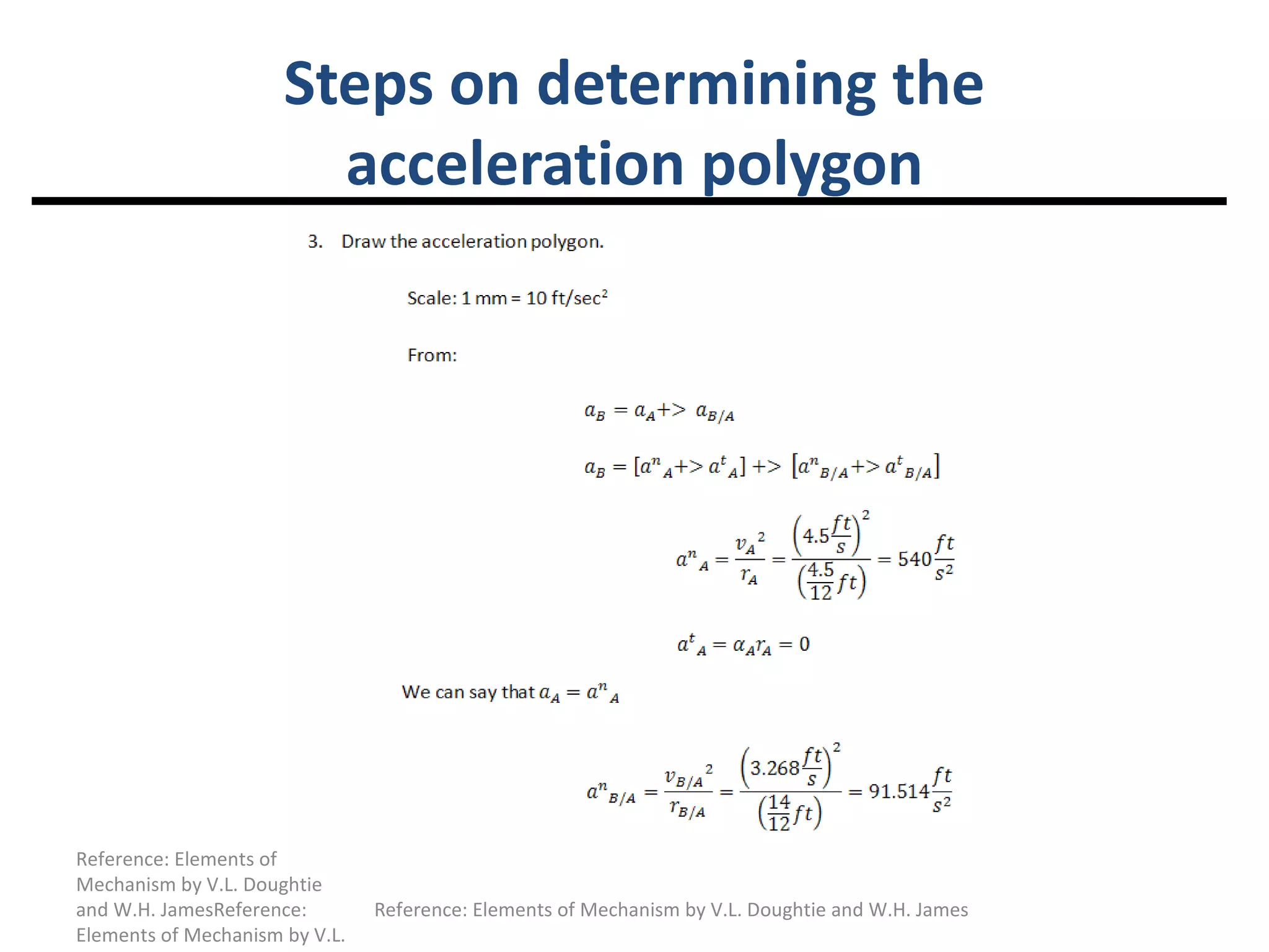
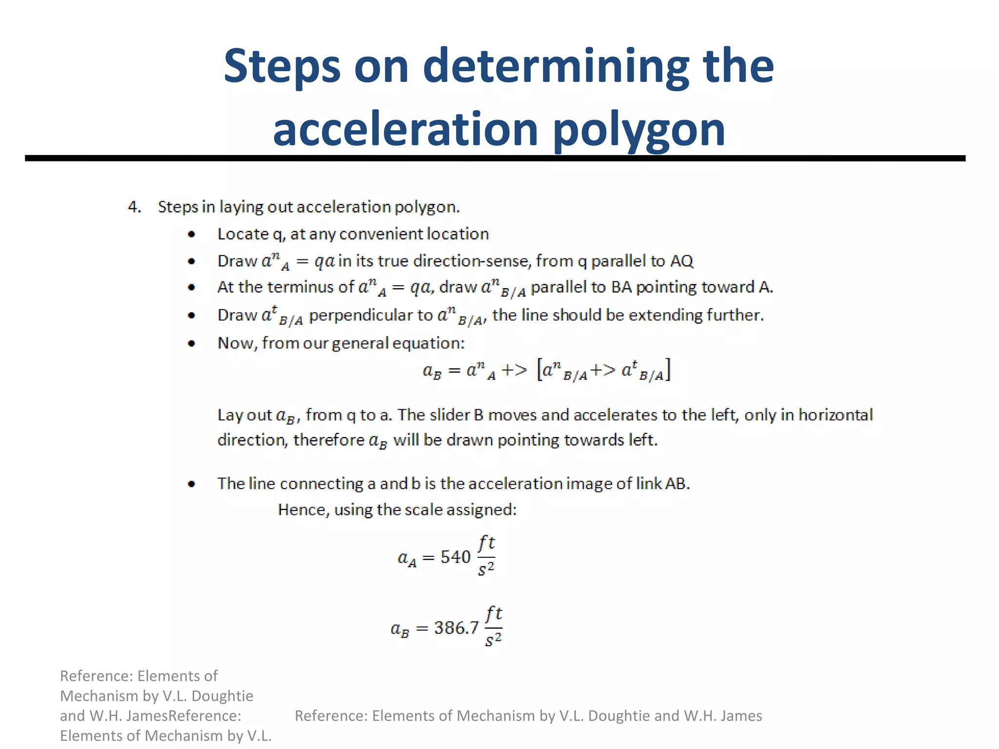
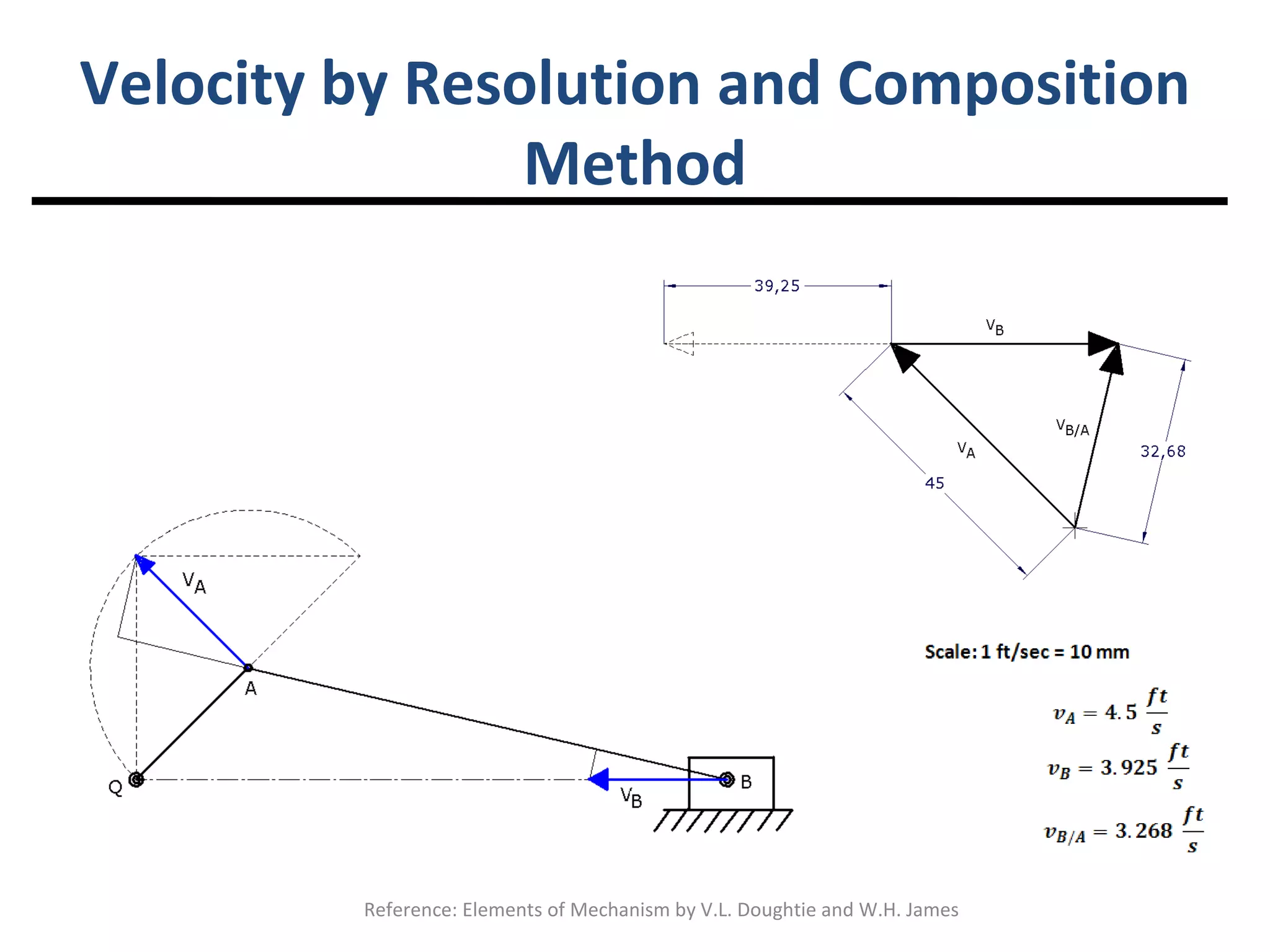
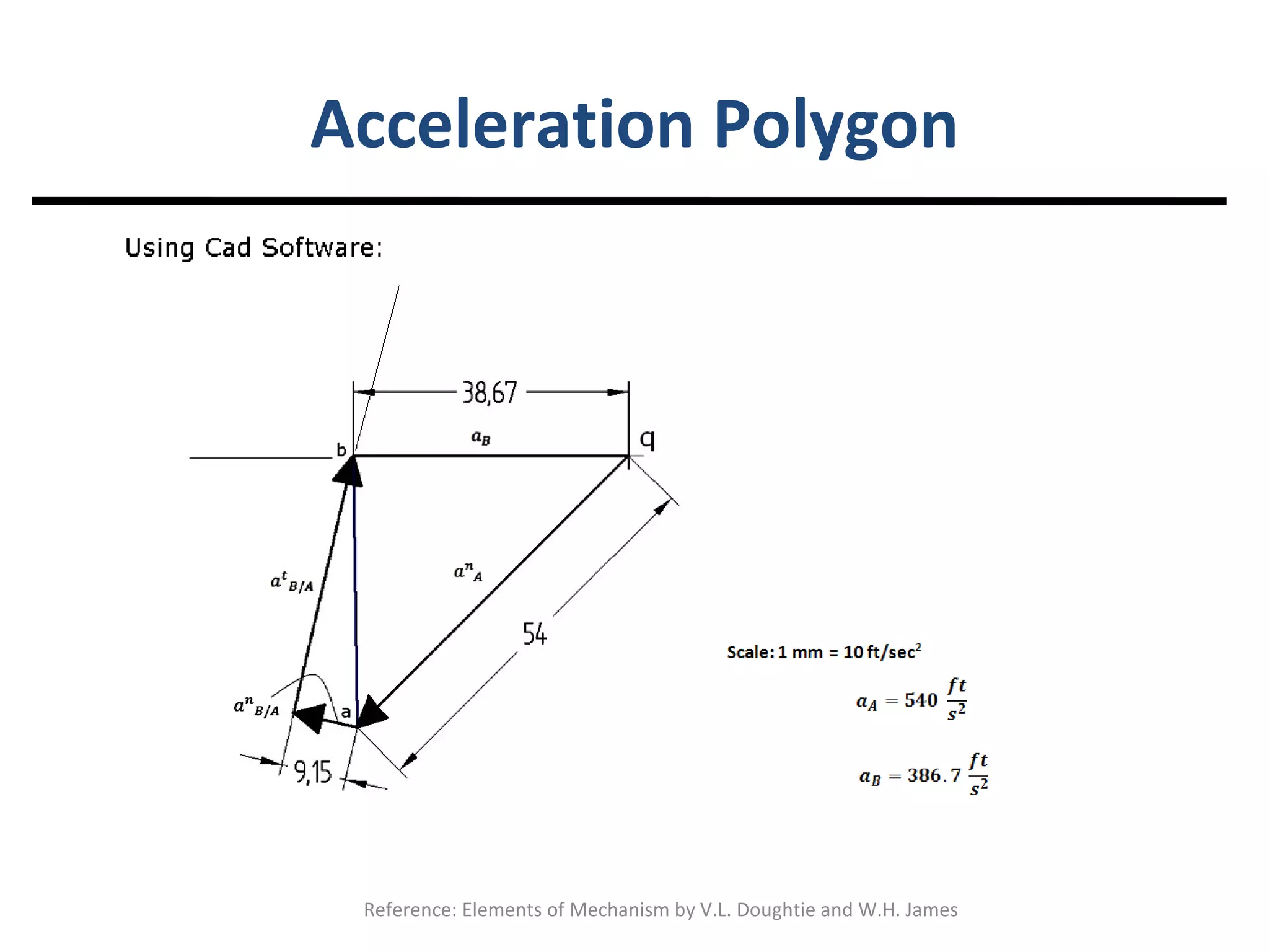
Relative Acceleration Lecture Notes
The Slider-Crank Mechanism The slider-crank mechanism probably is used in more machines than any other mechanisms. That is why special emphasis should be given to obtaining the velocities and accelerations in this mechanism. Owing to the fact that most acceleration analysis for this mechanism is made when the crank is turning uniformly, it will be assumed that the crank QA is turning in a  uniform angular velocity  counterclockwise.
Example 1: A slider-crank mechanism shown has the following dimensions. QA = 4.5 inches, AB = 14 inches. Determine the instantaneous linear acceleration of A and B. Uniform linear velocity of crank QA is 4.5 ft/sec counterclockwise. Reference: Elements of Mechanism by V.L. Doughtie and W.H. James
Steps on determining the acceleration polygon Reference: Elements of Mechanism by V.L. Doughtie and W.H. JamesReference: Elements of Mechanism by V.L. Doughtie and W.H. James Reference: Elements of Mechanism by V.L. Doughtie and W.H. James
Velocity by Resolution and Composition Method Reference: Elements of Mechanism by V.L. Doughtie and W.H. James
Acceleration Polygon Reference: Elements of Mechanism by V.L. Doughtie and W.H. James
Reference: Elements of Mechanism by V.L. Doughtie and W.H. James. © 1954 by John and Wiley and Sons, Inc. Page 97 - 98. Reference: Elements of Mechanism by V.L. Doughtie and W.H. James

010 relative acceleration

  • 1.
  • 2.
    The Slider-Crank MechanismThe slider-crank mechanism probably is used in more machines than any other mechanisms. That is why special emphasis should be given to obtaining the velocities and accelerations in this mechanism. Owing to the fact that most acceleration analysis for this mechanism is made when the crank is turning uniformly, it will be assumed that the crank QA is turning in a uniform angular velocity counterclockwise.
  • 3.
    Example 1: Aslider-crank mechanism shown has the following dimensions. QA = 4.5 inches, AB = 14 inches. Determine the instantaneous linear acceleration of A and B. Uniform linear velocity of crank QA is 4.5 ft/sec counterclockwise. Reference: Elements of Mechanism by V.L. Doughtie and W.H. James
  • 4.
    Steps on determiningthe acceleration polygon Reference: Elements of Mechanism by V.L. Doughtie and W.H. JamesReference: Elements of Mechanism by V.L. Doughtie and W.H. James Reference: Elements of Mechanism by V.L. Doughtie and W.H. James
  • 5.
    Steps on determiningthe acceleration polygon Reference: Elements of Mechanism by V.L. Doughtie and W.H. JamesReference: Elements of Mechanism by V.L. Doughtie and W.H. James Reference: Elements of Mechanism by V.L. Doughtie and W.H. James
  • 6.
    Steps on determiningthe acceleration polygon Reference: Elements of Mechanism by V.L. Doughtie and W.H. JamesReference: Elements of Mechanism by V.L. Doughtie and W.H. James Reference: Elements of Mechanism by V.L. Doughtie and W.H. James
  • 7.
    Velocity by Resolutionand Composition Method Reference: Elements of Mechanism by V.L. Doughtie and W.H. James
  • 8.
    Acceleration Polygon Reference:Elements of Mechanism by V.L. Doughtie and W.H. James
  • 9.
    Reference: Elements ofMechanism by V.L. Doughtie and W.H. James. © 1954 by John and Wiley and Sons, Inc. Page 97 - 98. Reference: Elements of Mechanism by V.L. Doughtie and W.H. James