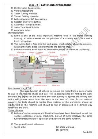
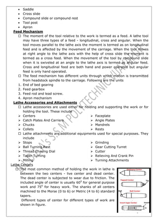
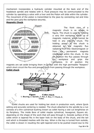
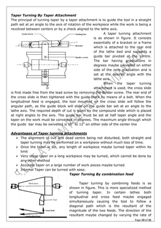
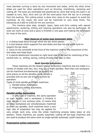
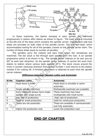
SlideShare a Scribd company logo
1 of 31
Download to read offline
Page 1 of 31
B.L.D.E.ASSOCIATION’S
SHREE SANGANABASAVA MAHASWAMIJI
POLYTECHNIC, VIJAYAPUR-03
SUB:- MACHINE TOOL TECHNOLOGY
SUB CODE :- 15ME43T
UNIT – 2
LATHE AND OPERATIONS
Lecturer :- S.V.Kulkarni
Page 2 of 31
Unit - 2 : LATHE AND OPERATIONS
 Center Lathe-Construction
 Various Operations
 Taper Turning Methods
 Thread Cutting operation
 Lathe Attachments& Accessories.
 Capstan and Turret Lathes
 Automats – Single Spindle
 Swiss Type Multi Spindle
 Automatic lathe.
INTRODUCTION
 Lathe is one of the most important machine tools in the metal working
industry. A lathe operates on the principle of a rotating work piece and a
fixed cutting tool.
 The cutting tool is feed into the work piece, which rotates about its own axis,
causing the work piece to be formed to the desired shape.
 Lathe machine is also known as “the mother/father of the entire tool family”.
Functions of the LATHE
The main function of lathe is to remove the metal from a piece of work
to give it the required shape and size. This is accomplished by holding the work
securely and rigidly on the machine and then turning it against the cutting tool
which will remove metal from the work in the form of chips. To cut material
properly the tools should be harder than material of the workpiece, should be
rigidly held on the machine and should be fed or progressed in it definite way
relative to the work.
Types of Lathe
 Lathes of various designs and Constructions have been developed to suit the
various conditions of metal machining. But all of them employee the same
fundamental principle of operation and perform the same function.
 The generally used lathes are
1. Speed lathe (a) Wood working
(b) Spinning
Page 3 of 31
(c) Centering
(d) Po1ishing
2. Center or engine lathe
(a) Be1t drive
(b) Individual motor drive
(c) Gear head lathe
3. Bench lathe
4. Tool room Lathe
5. Capstan and Turret 1athe
6. Special purpose lathe
(a) Whee1 lathe
(b) Gap bed lathe
(c) Dup1icating lathe
(d) T-lathe
7. Automatic lathe
Speed lathe
Speed lathe is simplest of all types of lathes in construction and
operation. It consists of bed, a headstock, a tailstock and a tool post mounted on
an adjustable slide. There is no feed box, lead screw or conventional type of
carriage. The tool is mounted on the adjustable slide and is fed into work purely by
hand control the characteristics of the lathe enables the designer to give a higher
spindle speed which usually range from 1200 to 3600 RPM as the tool is controlled
by the hand the depth of the cut and thickness of chip is very small.
The headstock construction is very simple and only 2 or 3 spindle
speeds are available. Light cuts and highest speeds necessitate the use of this type
of machine where cutting force is minimum such as in
 Woodworking
 Spinning
 Centering
 Polishing etc.
Engine Lathe or Center Lathe
This lathe is the most important member of the lathe family and is the
most widely used. The term engine is associated with the lathe owing to the fact
that early lathe where driven by steam engines similar to the speed lathe. The
engine lathe has got all the basic parts for example bed, head stock and tailstock,
but the headstock of the engine lathe is much more robust in construction and it
contains additional mechanism for driving the lathe spindle at multiple speeds.
Unlike the speed limit the engine lathe can feed the cutting tool both in cross and
longitudinal direction with reference to the axis with the help of a carriage, feed rod
and lead screw with these additional features an engine lathe has proved to be a
versatile machine adopted for every type of lathe work.
Engine lathes are classified according to the various designs
of the headstock and methods of transmitting power
(a)Belt drive
(b) Individual motor drive
(c) Gear head lathe
Bench Lathe
This is small lathe usually mounted on a bench. It has practically all the parts
of an engine lathe or speed lathe and it performs almost all the operations, its only
difference being in the size. This is used for small and precision work
Page 4 of 31
The Tool room Lathe
The tool room lathe having features similar to engine lathe is
much more accurately built and has a wide range of spindle speeds ranging from a
very low to quite high speed up to 2500 RPM. This is equipped, besides other
things, with a chuck, taper turning attachment, draw in collet attachment, thread
chasing dial, relieving attachment, Steady and follower rest, pump for coolant etc.
This lathe is mainly used for Precision work on tools, dial gauges and in machining
work where The accuracy is needed. The machine is costlier than an engine length
of the same size.
Capstan and Turret lathe
These lathes are development of the engine lathe and are used for
production work. The distinguishing feature of this type of lathe is that the tailstock
of an engine lathe is replaced by a hexagonal turret, on the face of which multiple
tools may be fitted and fed into the work in proper sequence. The advantage is that
several different types of operations which can be done on workpiece without re-
setting of work or tools, and a number of identical parts can be produced in the
minimum time.
Special Purpose lathe
As the name implies they are used for special purpose and for jobs
which cannot be accommodated or conveniently machined on a standard lathe. The
wheel lathe is made for finishing the journals and turning that tread on a railroad
car and locomotive wheels. The gap bed lathe, in which section of a bed adjacent to
the head stock is recoverable, is used to swing extra large diameter pieces. The T-
lathe a new member of the lathe family is intended for machining of rotors for Jet
engines. The axis of the lathe bed is at right angle to the axis of the headstock
spindle is the form of a T. The duplicating lathe is one for duplicate the shape of a
flat or round template on the work piece. Mechanical, air and Hydraulic devices are
also used to co-ordinate the movements of the tool to reproduce accurately the
shape of the template. The Missile lathe which has a very largest swing for
accommodating long missile component of very large diameter is the most modern
and latest in lathe design
Automatic Lathe
These are high speed heavy duty mass production lathe with the
complete automatic control. Once the tools are set and the machine is started it
performs automatically all the operations to finish that job. The changing of tools,
speed and feed are also done automatically. After the job is complete the machine
will continue to repeat the cycle producing identical parts even without the
attention of the operator and operator who has looked after for 5 or 6 automatic
lathe at a time will simply look after the general maintenance of the machine and
cutting tool, load up a bar stock and remove finished products from time to time
Page 5 of 31
Specification of Lathe
The size of the lathe is expressed or specified by the following factors.
 The height of centers - measured from the lathe bed.
 The swing diameter over bed - This is the largest diameter of work that will
revolve without touching the bed and is twice the height of the center
measured from the bed.
 The length between centers - This is maximum length of work that can be
mounted between the lathe center.
 The swing diameter over carriage - This is the largest diameter of work that
will revolve over the lathe saddle, and is always less than the swing diameter
over bed
 The maximum bar diameter -This is maximum diameter of bar stock that will
pass through hole of the headstock spindle.
 The length of bed - This indicates the approximate floor space occupied by
the lathe.
In ordering the lathe it is necessary to ask for certain other important
particulars to specify the lathe correctly. These are :
a) Width Of The Bed
b) Depth Of The Bed
c) Spindle Nose Diameter
d) Center Taper Morse Number
e) Range Of Spindle Speeds
f) No Of Feeds
g) Number And Range Of Metric And English Threads That May Be Cut
h) Pitch Value Of Lead Screw
i) Power Input
j) Floor area Required.
Page 6 of 31
CONSTRUCTION OF LATHE MACHINE
The basic parts of lathe machine are given as
1 Bed
2 Head stock
3 Tailstock
4 Carriage
5 Feed mechanism
6 Screw cutting mechanism
The Bed
 The lathe bed forms the base of the machine. The headstock and the tailstock
are located at either end of the bed and the carrier rests over the lathe bed
and slides on it. The lathe bed being the main guiding member of the tool, for
accurate machining work, must satisfy the following conditions
1. It should be sufficiently rigid to prevent defection.
2. It must be massive with sufficient depth and width to absorb vibration.
3. It must register that twisting stress set up due to the resultant of two
forces.
4. The bed should be seasoned naturally to avoid distortion or wrap that
may develop.
 On the top of the bed there are two sets of slides or guideways - outer ways
and innerways the outer guideways provide bearing and sliding surface for
the carriage and the innerways for the tailstock.
 The guideways of the lathe bed may be flat and inverted - V having an
included angle of 900
.
 The bed material should have high compressive strength should be wear
resistant and absorb vibration. Cast iron alloy with Nickel and chromium
forms a good material suitable for lathe bed.
The Headstock
 Headstock is secured permanently on the innerways at left hand end of the
lathe bed and it provides the mechanical mean of rotating the work at
multiple speeds. It comprises essentially a hollow spindle and mechanism for
driving and altering the spindle speed. All the parts are housed within the
headstock casting.
The Tailstock
 The tailstock is located on the innerways at the right hand end of the bed.
This has two main uses
1. It supports the other end of the work when it is being machined between
centers.
2. It holds a tool for performing operations such as drilling, reaming, tapping
etc.
The Carriage
 The Carriage has several parts that serve to support, move and control
cutting tool.
It consists of the following parts
Page 7 of 31
 Saddle
 Cross slide
 Compound slide or compound rest
 Tool post
 Apron
Feed Mechanism
 The moment of the tool relative to the work is termed as a feed. A lathe tool
may have three types of a feed - longitudinal, cross and angular. When the
tool moves parallel to the lathe axis the moment is termed as on longitudinal
feed and is affected by the movement of the carriage. When the tool moves
at right angle to the lathe axis with the help of cross slide the moment is
termed as a cross feed. When the movement of the tool by compound slide
when it is swiveled at an angle to the lathe axis is termed as angular feed.
Cross and longitudinal feed are both hand and power operated but angular
feed is only hand operated.
 The feed mechanism has different units through which motion is transmitted
from headstock spindle to the carriage. Following are the units
1. End of bed gearing
2. Feed gearbox
3. Feed rod and lead screw.
4. Apron mechanism
Lathe Accessories and Attachments
 Lathe accessories are used either for holding and supporting the work or for
holding the tool. These include
 Centers
 Catch Plates And Carriers
 Chucks
 Collets
 Faceplate
 Angle Plates
 Mandrels
 Rests
 Lathe attachments are additional equipments used for special purposes. They
include
 Stops
 Ball Turning Rest
 Thread Chasing Dial
 Taper Turning
 Milling
 Grinding
 Gear Cutting Turret
 Cutter
 Relieving And Crank Pin
 Turning Attachments
Lathe Centers
 The most common method of holding the work in lathe is
between the two centers - live center and dead center.
The dead center is subjected to wear due to friction. The
included angle of center is usually 600
for general purpose
work and 750
for heavy work. The shanks of all centers
machined to the Morse (0 to 6) or Metric (4 to 6) standard
tapers.
Different types of center for different types of work are
shown in figure.
Page 8 of 31
 The ordinary Center is a type used for most general work.
 In the tipped Center the point consists of a hard alloy tip brazed in to
ordinary Steel Shank this is more expensive type of center.
 The ball Center is used to minimize wear and strain on the ordinary center.
 The insert type of center is used for reasons of economy as only the high
speed Steel “insert” can be replaced instead of replacing the whole Center.
 The rotating or frictionless center is always used in
tailstock for supporting heavy work revolving at high
speed . An ordinary insert type center revolves freely
on the ball and the roller bearings fitted in a housing
having a tapper shank corresponding to the taper of the
tailstock spindle.
 The pipe center is used for supporting the end of
pipes, Shells etc.
Carriers and catch plates
Carriers and catch plates are used to drive a
workpiece when it is held between two centers. Carriers or driving dogs are attached
to the end of the work piece by a set screw, and catch plates are screwed or bolted
to the nose of the tailstock spindle. A
projecting pin from the catch plate or
carrier fits into the slot provided in either
of them. This is a positive drive between
the lathe spindle and workpiece. The
figure illustrates different types of cash
plate and Carriers. The projecting pin of
a Single pin catch plate drivers
the straight end or tale of carrier attached
to the work piece. Two pins of Double pin
catch plate engage with the Double tail or
Double slotted carrier and provide a
uniform drive. The Bent tail type is used in conjunction with a face plate or slotted
catch plate
CHUCK
Chuck is the one of the most important devices for holding and rotating a
piece of work in a lathe. Workpiece of short length and larger diameter of irregular
shape which cannot be conveniently mounted between Centers are held quickly and
rigidly in a chuck. A chuck is attached to the lathe spindle by means of bolt with the
back plate screwed on to the spindle nose. Accurate alignment of the chuck with the
lathe axis is effected by spigotting.
The different types of chucks are
1) Four jaw Independent Chuck
2) Three Jaw Universal Chuck
Page 9 of 31
3) Air Or Hydraulic Operated Chuck
4) Magnetic Chuck
5) Collet Chuck
6) Combination Chuck
7) Drill Chuck
Four jaw Independent Chuck
Four jaw independent chuck is as shown in
figure. This chuck has for jaws which may be
made to slide within the slots provided in the
body of the chuck for gripping different sizes of
workpiece. Each jaw may be moved
independently by rotating the screw which
meshes with the teeth cut on the underside of the
jaw. Each jaw made up of tough steel has a 3
inner and one outer gripping surfaces. Outer
gripping surface is used for holding larger sizes of
workpiece by reversing the jaw. Concentric circles inscribed on the face of the chuck
facilitate quick centering of the workpiece .This type of chuck is particularly used in
the setting up of heavy and irregular shaped articles. The diameter of the body is
specifies the size of the chuck.
Three jaw universal chuck
Three Jaw Universal chuck is as shown
in figure. All the jaw may be made to slide
simultaneously by an equal amount within the
slots provided on the body, by rotating any one of
the three pinions which meshes with the teeth cut
on the underside of the scroll disc. The scroll disc
having a spiral groove cut on the top face meshes
with the teeth on the jaws. When the disc is made
to rotate by any one of the pinion all the three
jaws moves backward or forward by equal
amount. The chuck is suitable for holding round,
or hexagonal and other similar shaped workpiece and the job is centered
automatically and quickly but it has less gripping capacity as only three jaws are
used and centering accuracy is soon lost due to wear.
Air Or Hydraulic Operated Chuck
Air or
hydraulic operated chuck
is as shown in figure. It
is used in mass
production work for its
fast and effective
gripping capacity. The
Page 10 of 31
mechanism incorporates a hydraulic cylinder mounted at the back end of the
headstock spindle and rotates with it. Fluid pressure may be communicated to the
cylinder by operating a valve with a liver and the Piston will slide within the cylinder.
The movement of the piston is transmitted to the jaws by connecting rod and links
and the jaws grip the workpiece securely.
Magnetic Chuck
The front view of a
magnetic chuck is as shown in
figure. The chuck is used for holding
a very thin workpiece made up of
magnetic material, which cannot be
held in any ordinary chuck. The
holding power of the chuck is
obtained by the magnetic flux
radiating from the Electromagnet or
from the permanent magnets
introduced within the chuck. In the
On position the flux passes through
the workpiece and grips the
workpiece. In of position the
magnets are set aside bringing them in contact with the high permeable “Keepers”
which short circuit the flux and prevent them from passing through the workpiece.
Collet chuck
Collet chucks are used for holding bar stock in production work, where Quick
setting and accurate centering is needed. The chuck attached to the spindle by a nut
consists of a thin cylindrical bushing known as collet having a slot cut lengthwise on
its Periphery. The inside Bore of collet maybe cylindrical, hexagonal, Square etc.
depending on the shape of the work that will pass through it. Outside surface of the
collet which is tapered fits in the taper hole on the body of the chuck, and the tail
end which is threaded meshes with the key. When is the key is turned from outside,
the collet is drawn in resulting the split tapered end to be pushed inward due to the
Page 11 of 31
spring action and the workpiece is a securely and accurately held in the chuck.
Different sizes of collets are used for holding different sizes of the bar stock.
Combination chuck
The combination chuck is as shown in
figure. It may be used both as a self centering and
an independent chuck to take advantage of both
types. The jaws may be operated individually by
separate screw or simultaneously by scroll disc. The
screws mounted on the frame have teeth cut on its
underside which meshes with the scroll and all the
jaws together with the screws move radially when
the scroll is made to rotate by a pinion.
Drill chuck
Drill chuck is sometimes used in the lathe for
holding Straight Shank drill Reamer or tap for drilling, reaming or tapping operations.
The chuck may be held either in headstock Or tailstock spindle. It has self centering
jaws which may be operated by rotating a key.
Face plate
The fig shows the schematic representation of
Face plate. It consists of a circular disc bored
out and threaded to fit the nose of the lathe
spindle. This has a radial plane and „T‟ slot for
holding work by bolts and clamps. Face plates
are used for holding workpiece which cannot be
conveniently held between centers or by
chucks.
Angle plates
This is a cast iron plate having two faces
machined to make them absolutely at right angles to
each other. Holes and slots are provided on both faces so
that it may be clamped on a faceplate and can hold the
workpiece on the other face by bolts and clamps. Angle
plates are used in conjunction with a face plate when the
holding surface of the workpiece should be kept
horizontal, as for example, in machining a flange of a
pipe elbow. When eccentric jobs are bolted to the face
plate, a balance weight or counter weight must be added.
Mandrels
Page 12 of 31
A mandrel is a device used for holding and rotating a hollow piece of work that
has been previously drilled or bored. The work revolves with the mandrel which is
mounted between two centers. The mandrel should be true with accurate center
holes, for machining outer surface of work piece concentric with its bore. These are
made with the help of high carbon steel to avoid distortion and wear. The ends of the
mandrel are slightly smaller in diameter and flattened to provide effective gripping
surface of the lathe . The mandrel is rotated by the lathe dog and the catch plate and
drives the work by friction. Different types of mandrels are employed according
specific requirement.
Types of Mandrels
Plane mandrel is most commonly
used in shops and finds wide
application where a large number of
identical pieces having standard holes
are required to be mounted on it
A steep mandrel having steeps of different
diameters may be employed to drive different
workpieces having different sizes of holes without
replacing the mandrel.
A collar mandrel having solid
collars is used for turning workpieces
having holes of larger diameter,
usually above 100 mm.
A screwed mandrel is threaded at one end
with collar. Workpieces having internal threads are
screwed on to it for machining.
it consist of solid cone
attached to the one end of the
Page 13 of 31
body, and sliding cone at other end which can be adjusted by turning a nut. This
type is suitable for holding workpieces having different diameter.
The Gang mandrel has a fixed collar at one end and a movable collar at the threaded
end which will be adjusted to this
position by nut.
The Expansion mandrel can be
used to grip various workpiece with
different hole diameters within a
limit. This can be used in repairing
workshops.
Rests
Rest is a mechanical device which supports a long Slender workpiece, which is
turned between centers or by a clutch, at some intermediate point to prevent
bending of the workpiece due to its own weight and vibrations set up due to the
cutting force that acts on it. A rest should always be used when the length is 10 to
12 times the diameter of the workpiece. Rests when properly set provide greatest
accuracy in machining and permit heavier depth of cut on the workpieces. The two
types of rest used in engine lathe are
1. Steady or Centre rest
2. Follower rest
Steady or Center Rests
Steady rest is as shown in
figure. It consists of a cast iron base,
which may be made to slide on the
lathe bedways and clamped at any
desired position where a support is
necessary. This is so designed that
the upper portion is hinged at one
end which facilitates setting and
removal of workpiece without
disturbing the position of the Steady
rest. The three jaws on the Steady
rest, two on the lower base and one
on the upper frame, may be adjusted
radially by rotating individual screws
to accommodate workpiece of
different diameter. The jaws which
act as a bearing to the workpiece are
clamped in position after the setting
is properly made. They rest on a spot on the work which has been previously turned
Page 14 of 31
to provide the true bearing surface. The main function of the Steady rest is to
provide support to a long slender work. For this purpose one more Steady rest may
be used to support the free end of the workpiece . It is also used to support the free
end of long workpiece for drilling, boring, tapping operations etc. When support from
the tailstock cannot be given. The carriage cannot be fed to the full length of the
work when the Steady rest is used
Follower Rest
A follower rest is as shown in
figure. It consists of a „C‟ like casting
having 2 adjustable jaws which support
the workpiece. The rest is bolted to the
back end of the carriage and moves
with it. Before setting the follower rest,
the end of the workpiece is machined
slightly wider than the jaws to provide
the true bearing surface. The tool is set
slightly in advanced position than the
jaws, and as the tool is fed longitudinal
by the carriage, the Jaws always follow
the tool giving continuous support to
the workpiece. The follower rest
prevents the job from springing away
when the cut is made and is used in
finish turning operations or where the entire length of the workpiece is required to be
turned without disturbing the setting.
LATHE OPERATIONS
In order to perform different machining operations in a lathe, the
workpiece may be supported and driven by any one of the following methods :
1. Held between centers and driven by carriers and catch plates.
2. Held on a mandrel which is supported between centers and driven by carriers
and catch plates.
3. Held and driven by chuck with other end supported on the tailstock center.
4. Held and driven by a chuck or a faceplate or an angle plate.
Operations which are performed in a lathe either by holding the workpiece
between centers or by a chuck are
1. Straight Turning
2. Shoulder Turning
3. Chamfering
4. Thread Cutting
5. Facing
6. Knurling
7. Filing
8. Tapper Turning
9. Eccentric Turning
10. Polishing
11. Grooving
12. Spinning
13. Spring winding
14. Forming
Page 15 of 31
Operations which are performed by holding the work by a chuck or faceplate or
an angle plate
1. Drilling
2. Reaming
3. Boring
4. Counter boring
5. Taper boring
6. Internal thread cutting
7. Tapping
8. Undercutting
9. Parting-off
Operations which are performed by using special attachments are :
1. Grinding
2. Milling
CENTERING
Where the work is required to be turned between centers or between a
chuck and center, conical shaped holes must be provided at the ends of workpiece to
provide bearing surface for lathe centers. Centering is the operation of producing
conical holes in workpiece.
TURNING
Turning in a lathe is to remove excess material from the workpiece to
produce a cone –shaped or a cylindrical surface. The various types of turning made
in lathe work for various purpose are described below.
Straight turning : The work is turned straight when it is made to rotate about the
lathe axis, and the tool is fed parallel to the lathe axis. The straight turning produces
a cylindrical surface by removing excess metal from the workpiece.
ROUGH TURNING
The rough turning is the
process of removal of excess material
from the workpiece in a minimum time
by applying high rate of feed and heavy
depth of cut. The roughing cut should
be so made that the machine, the tool
,and the workpiece can bear the load
and it does not make too rough surface
and spoil the centers. The depth of cut
for roughing operations in average
machine shop work is from 2 to 5 mm
and the rate of feed is from 0.3 to 1.5
mm per revolution of the work.
Page 16 of 31
FINISH TURNING
The finish turning operation
requires high cutting speed, small feed,
and a very small depth of cut to generate
a smooth surface. A finish turning tool
having sharp cutting edge is held securely
on the tool post for this purpose. In finish
turning operation as shown in fig the
depth of cut ranges from 0.5 to 1mm and
feed from 0.1 to 0.3 mm per revolution of
the workpiece.
SHOULDER TURNING
When a workpiece
having different diameters is turned, the
surface forming the step from one diameter to the other is called the shoulder, and
machining this part of the workpiece is called as
shoulder turning. There are four types of
shoulders
(1) Square shoulder
(2) Angular shoulder
(3) Radius shoulder
(4) Under cut shoulder
TAPERS AND TAPER TURNING
A taper may be defined as a uniform increase or decrease in
diameter of a piece of work measured along its length. In a lathe, taper turning
means to produce a conical surface by gradual reduction in diameter from a
cylindrical workpiece. This tapering of part has wide applications in the construction
of machines. Almost all machine spindles have taper holes which receive taper shank
of various tools and work holding devices.
Taper Elements
A tapered piece is as shown in fig, it
may be designated by the following
symbols.
D= Larger Diameter of taper in mm ;
d = Small Diameter of taper in mm ;
l = length of taper in mm ; 2 α = Full
taper angle ; α = Half taper angle
Page 17 of 31
Conicity
The amount of taper in a workpiece is usually specified by the ratio of the
difference in diameters of the taper to its length. This is termed as the conicity and
its designated by the letter K.
K = D – d
l
Taper angle - α
The taper of workpiece is sometimes expressed by the angle „α‟
the half taper angle or the angle of taper.
Taper Turning Methods
A taper may be turned in a lathe by feeding the tool at an angle to the
axis of rotation of the workpiece. The angle formed by the path of the tool with the
axis of the workpiece should correspond to the half taper angle.
while turning taper, it is essential that the tool cutting edge should be set
accurately on the center line of the workpiece, otherwise correct taper will not be
obtained. A taper may be turned by any one of the following methods.
1. By A Broad Nose Form Tool
2. By Setting Over The Tailstock Center
3. By Swivelling The Compound Rest
4. By Taper Turning Attachment
5. By Combining Longitudinal And Cross Feed In A Special Lathe.
Taper Turning By A Form Tool
The above figure illustrates the
method of taper turning by form tool. A
broad nose tool having straight cutting
edge is set on to the work at half taper
angle, and is fed straight into the work
to generate a tapered surface. The half
angle of taper will correspond to 90
minus side cutting edge angle of the
tool. In this method the tool angle
should be properly checked before use. This method is limited to turn short length of
taper only. This is due to the reason that the metal is removed by the entire cutting
edge and any increase in the length of the taper will necessitate the use of a wider
Page 18 of 31
cutting edge . This will require excessive cutting pressure, which may distort the
work due to vibration and spoil the work surface.
Taper Turning By Setting Over The Tailstock
The principle of turning taper by this method is to shift the axis of rotation of
the workpiece, at an angle to the lathe axis, and feeding the tool parallel to the lathe
axis. The angle at which the axis of rotation of the workpiece is shifted is equal to
half angle of the taper. This is done when the body of the tailstock is made to slide
on its base towards or away from the operator by a setover screw as shown in figure.
The amount of setover being limited, this method is suitable for turning small taper
on long jobs. The main disadvantage of this method is that the live and dead centers
are not equally stressed and the wear is not uniform, moreover the lathe carrier
being set at an angle, the angular velocity of the work is not constant.
Taper Turning By Swivelling The Compound Rest
This method employs the
principle of turning taper by
rotating the workpiece on the lathe
axis and feeding the tool at an
angle to the axis of rotation of the
workpiece. The tool mounted on
the compound rest is attached to a
circular base, graduated in degree,
which may be swivelled and
clamped at any desired angle. This
is illustrated in figure. Once the compound rest is set at the desired half taper angle,
rotation of the compound slide screw will cause the tool to be fed at that angle and
generate a corresponding taper. This method is limited to turn a short taper owing to
the limited movement of the compound rest. But a small taper may also be turned.
The compound rest may be swivelled at 450
on either side of the lathe axis enabling
it turn step taper. The movement of the tool in this method being purely controlled
by hand, this gives a low production capacity and poorer surface finish.
Page 19 of 31
Taper Turning By Taper Attachment
The principal of turning taper by a taper attachment is to guide the tool in a straight
path set at an angle to the axis of rotation of the workpiece while the work is being a
revolved between centers or by a check aligned to the lathe axis.
A taper turning attachment
is as shown in figure. It consists
essentially of a bracket or a frame
which is attached to the rear end
of the lathe bed and supports a
guide bar pivoted at the centre.
The bar having graduations in
degrees maybe swivelled on either
side of the zero graduation and is
set at the desired angle with the
lathe axis.
When the taper turning
attachment is used, the cross slide
is first made free from the lead screw by removing the Binder screw. The rear end of
the cross slide is then tightened with the guide block by means of a bolt. When the
longitudinal feed is engaged, the tool mounted on the cross slide will follow the
angular path, as the guide block will slide on the guide bar set at an angle to the
lathe axis. The required depth of cut is given by the compound slide which is placed
at right angles to the axis. The guide bar must be set at half taper angle and the
taper on the work must be converted in degrees. The maximum angle through which
the guide bar may be swivelled is 100
to 120
on either side of the center line
Advantages of Taper turning attachments
 The alignment of live and dead centre being not disturbed, both straight and
taper turning may be performed on a workpiece without much loss of time.
 Once the taper is set, any length of workpiece maybe turned taper within its
limit
 Very steep taper on a long workpiece may be turned, which cannot be done by
any other method
 Accurate taper on a large number of work pieces maybe turned
 Internal Taper can be turned with ease.
Taper Turning By combination feed
Taper turning by combining feeds is as
shown in figure. This is more specialized method
of turning taper. In certain lathes both
longitudinal and cross feed maybe engaged
simultaneously causing the tool to follow a
diagonal path which is the resultant of the
magnitude of the two feeds. The direction of the
resultant maybe changed by varying the rate of
Page 20 of 31
feeds by change gears provided inside the apron
Eccentric Turning
When a circular workpiece has two separate axis of rotation, one
being out of Centre to the other, then the workpiece is known as eccentric and
turning of such workpiece is known as eccentric turning. The figure shows the
turning of crankshaft in lathe.
To turn the eccentric surface two sets of centre holes are drilled at the
ends of the workpiece. The centre holes are offset from the normal axis of the
workpiece. The amount of offset is equal to half of the eccentricity required. First, the
workpiece is mounted on it's true centre. The journal portion of the workpiece is
turned. Then the work is a mounted on the offset centre to turn eccentric portion of
the workpiece. Counter balance weights are mounted on the face plate to get
uniform turning moment.
CHAMFERING
Chamfering is the operation of bevelling the extreme end of a workpiece. This
is done to remove the burrs, to protect the end of the workpiece from being
damaged and to have a better look. The operation may be performed after knurling,
rough turning, boring, drilling or thread cutting. Chamfering is an essential operation
after thread cutting so that the nut may pass freely on the threaded workpiece.
THREAD CUTTING
Thread cutting is one of the most important operations performed in
lathe. The principle of thread cutting is to produce a helical groove on a cylindrical or
conical surface by feeding the tool longitudinally when the job is revolved between
centers or by a chuck. The longitudinal feed should be equal to the pitch of the
thread to be cut per revolution of the workpiece. The leadscrew of the lathe, through
which the saddle receives its traversing motion, has a definite pitch. A definite ratio
Page 21 of 31
between the longitudinal feed and rotation of the headstock spindle should therefore
be found out so that the relative speeds of rotation of the work and leadscrew will
result in the cutting of a screw of the desired pitch. This is effected by change gears
arranged between the spindle and the leadscrew or by the change gear mechanism
or feed box used in a modern lathes where it provides a wider range of feed and the
speed ratio can be easily and quickly changed .
Calculation for change – wheels
To calculate the wheels required for cutting a screw of certain pitch it is
necessary to know how the ratio is obtained , and exactly where the driving driven
wheels are to be placed.
Driver teeth = Pitch of the work
Driven teeth Pitch of the leadscrew
FACING
Facing is the operation of machining the ends of a piece of work to produce a
flat surface square with the axis. This is also used to cut the work to the required
length. The operation involves feeding the tool perpendicular to the axis of rotation
of the workpiece.
KNURLING
Knurling is the process of embossing a diamond shaped pattern on the surface
of a workpiece. The purpose of knurling is to provide an effective gripping surface on
a workpiece to prevent it from slipping when operated by hand.
FILING
Filing is the finishing operation performed after turning. This is done in a lathe
to remove burrs, sharp corners, and feed marks on a workpiece and also to bring it
to the size by removing very small amount of metal.
POLISHING
Polishing is performed after filing to improve the surface quality of the
workpiece. Polishing with successively finer grades of emery cloth after filling results
Page 22 of 31
in very smooth, bright surface. The lathe is run at high speeds from 1500 to 1800m
per min, and oil is used on the emery cloth.
GROOVING
Grooving is the process of reducing the diameter of a workpiece over a very
narrow surface. It is often done at the end of the thread or adjacent to a shoulder to
leave a small margin.
SPINNING
Spinning is the process of farming a thin sheet of metal by revolving the job at
high speed and pressing it against a “former” attached to the headstock spindle. A
support is also given from the tailstock end. The pressure is gradually applied to the
revolving sheet metal by a long round nose forming tool supported on the special
tool rest when the piece slowly acquires the shape of the former.
SPRING WINDING
Spring winding is the process of making a coiled spring by passing a wire
around a mandrel which is revolved on a check or between centers.
FORMING
Forming is the process of turning a convex concave or of any irregular shape.
Form turning may be accomplished by the following methods.
1. Using a forming tool
2. Combining across land longitudinal feed
3. Tracing are copying a template
Operations which are performed by holding the work by a chuck or
faceplate or an angle plate
DRILLING
Drilling is the operation of producing a cylindrical hole in a workpiece by the
rotating cutting edge of the cutter known as the drill. Drilling in a lathe is performed
by any one of the following methods.
1. The workpiece is revolved in a check or a face plate and the drill is held in a
tailstock drill holder or in a drill chuck.
2. The drill is held and driven by drill check attached to the headstock spindle and
the work is held against a pad or crotch supported by the tailstock spindle.
REAMING
Reaming is the operation of finishing and sizing a hole which has been
previously drilled or board. The tool used is called the reamer, which has multiple
cutting edges.
BORING
Boring is the operation of enlarging and turning a hole produced by drilling,
punching, casting or forging. Boring cannot create a hole.
COUNTERBORING
Counter boring is the operation of enlarging a hole through a certain distance
from one end instead of enlarging the whole drilled surface. It is similar to a shoulder
work in external turning. The operation is similar to boring and a plain boring tool or
a counter boring tool may be used.
TAPER BORING
Page 23 of 31
The principle of turning a taper hole is similar to the external taper turning
operation and is accomplished by rotating the work on a check or a face plate, and
feeding the tool at an angle to the axis of rotation of the workpiece.
INTERNAL THREAD CUTTING
The principle of cutting internal threads is similar to that of external thread.
The only difference being the tool used. The tool is similar to boring tool which
cutting edges ground to the shape confirming to the type of thread to be cut. The
hole is first bored to the root diameter of the thread. For cutting metric thread , the
compound slide is 300
towards the headstock. The tool is a fixed on the tool post or
on the Boring bar after setting it right angle to the axis, using a thread gauge. The
depth of cut is given by the compound slide and the thread is finished in the usual
manner.
TAPPING
Typing is the operation of cutting internal threads of small diameter using a
multipoint cutting tool called attack the tab tap in a lead the work is mounted on a
check or on a face plate and devolved at very slow speed itapp of a required size
held on a special features is mounted on the tailstock spindle the axis of the tap
should go inside exactly with the axis of the work that will automatically filled in to
the work with the help of special fixture.
UNDER CUTTING
Undercutting is similar to grooving operation and performed inside a hole. It is
the process of boring a groove or a large hole at a fixed distance from the end of a
hole this is similar to boring operation except that square nose parting tool is used.
PARTING-OFF
Parting-off is the operation of cutting a workpiece after it has been machined to
the desired size and shape. The process involves rotating the workpiece on a chuck
or faceplate at half the speed that of turning and feeding by a narrow parting-off tool
perpendicular to the axis by rotating the cross slide screw by hand.
Operations which are performed by using speacial attachments
MILLING
Milling is the operation of removing metal by feeding the work against a
rotating cutter having multiple cutting edges. It is performed in a lathe by any one of
the two methods.
1. For cutting key ways or groves the work is supported on the cross slide by a
special attachment and fed against a rotating milling cutter held by a check.
The depth of cut is given by vertical adjustment of the work provided by the
attachment.
2. The work maybe supported between centers and held stationary. The
attachment mounted on a carrier drives the cutter from an individual motor.
The feeding movement is provided by the carriage.
GRINDING
Grinding is the operation of removing metal in the form of minute chips by
feeding the work against a rotating abrasive wheel known as a grinding wheel. Both
internal and external surfaces of a workpiece may be ground by using a special
attachment mounted on a cross slide. For grinding external surface, the work may be
revolved between centers or on chuck. For internal grinding the work must be
Page 24 of 31
revolved on a chuck or faceplate. Grinding is performed in a lathe for finishing a job,
sharpening a cutter, or sizing a workpiece after it has been hardened.
Cutting Speed, Feed, Depth of cut and Machining time
Cutting Speed
The cutting speed of tool is the speed at which the metal is removed by the
tool from the workpiece in a lathe it is the peripheral speed of the work past the
cutting tool expressed in metres per minute.
Feed
The feed of a cutting tool in a lathe work is the distance the tool advances for
each revolution of the work. Feed is expressed in millimeters per revolution.
Increased speed reducers cutting time, but increased feed gradually reduces the tool
life. The feed depends on the factors such as sizes shapes strength and method of
holding the component.
Depth of Cut
The depth of cut is the perpendicular distance measured from the machined
surface to the uncut surface of the workpiece. In a lathe the depth of cut is
expressed as follows
Depth of cut = d1 - d2
2
Where,
d1= diameter of the work surface before machining
d2 = diameter of the machined surface
Machining time
The machining time in lathe work can be calculated for a particular
operation if the speed of the job, feed length of the job is known. If „s‟ is the feed of
the job per revolution expressed in mm per revolution and „l‟ the length of the job in
mm, the number of revolutions of the job required for complete cut will be:
If the r.p.m of the work is time taken to revolve the job through l/s
number reservations for a complete cut will be
Therefore time taken for complete cut = l min
s X n
Capstan and Turret Lathes
These lathes are the advanced development of engine lathes. The capstan or
turret lathe is used to manufacture any number of identical pieces in a minimum
time. The construction and working principle of capstan and turret lathes are same.
The capstan lathes are used to light and small jobs and turret lathes are used for
heavy and large jobs.
Construction and Working
The capstan or turret lathe consists of a bed, all geared headstock, and a
saddle on which a four station tool post is mounted to hold four different tools. A one
more tool post is fitted at the rear of the carriage to hold parting tool in an inverted
position. The tool post mounted on the cross slide is indexed by hand. In capstan and
Page 25 of 31
turret lathe there is no tailstock, instead in its place a hexagonal turret is mounted
on a slide which rests upon the bed. All the six faces of the turret can hold six or
more number of different tools. The turret may be indexed automatically and each
tool may be brought in line with the lathe axis in a regular sequence. The workpices
are held in collets or in chucks, and at least eleven tools can be held at a time, six
tools are held on a turret faces, four tools on front tool post and one at rear tool
post. During machining, the chuck or collet holding the job rotates with a definite
speed. The turret head moves forward towards the job.
After each operation, the turret goes back to its position. The turret is indexed
automatically and the tools mounted on the, next face comes into operation. The
longitudinal and cross feed movement of the turret saddle and cross-slide are
regulated by adjustable stops. These stops enable different tools set at different
stations to move by a predetermined amount for performing different operations on
repetitive workpieces without measuring the length or diameter or the machined
surface in each case. Such special characteristics of a capstan or turret lathe enables
it to perform a series of operations like turning, drilling, boring, thread cuttings,
reaming, necking, chamfering, cutting off and many other operations in regular
sequence to produce a large number of identical pieces in shortest time.
Capstan lathe
Turret lathe
Page 26 of 31
There are two main types of this family
i) The capstan or ram type lathe
The fig. shows the capstan or ram type lathe.
It consists of hexagonal turret on a ram. The ram
slides longitudinally on a saddle positioned and
clamped on a lathe bed ways which also slides over
the lathe bed longitudinally. The tools are mounted
on the square turret and six faces of the hexagonal
turret. The feeding movement is obtained when the
ram moves from left to right and when ram moves
backward the turret indexes automatically and the
tools mounted next face comes into operation.
ii) The turret or saddle type lathe as shown in fig
The turret or saddle type lathe is as shown in Fig. The hexagonal turret is
directly mounted on a saddle and the whole unit moves back and forth on the
bedways to apply feed. These lathes are heavier in construction and are used for
larger diameter heavier bar work and chucking work. The machine accommodate
longer workpiece than that in a capstan lathe.
Difference between Capstan and Turret Lathes
SL.
NO
CAPSTAN TURRET
1 It is suitable for light and small jobs. It is suitable for heavy and large jobs.
2 The turret is mounted on ram which
slides over the saddle.
The turret is mounted on saddle which
slides directly on the bed.
3 The travel of the turret depends on
the length of travel of ram.
The saddle directly slides over entire
length of a bed carrying turret.
4 Only short length workpieces can be
machined.
Longer workpieces can be machined.
Page 27 of 31
5 The construction provides non-
rigidity to the tool support.
The construction provides outmost
rigidity to the tool support.
6 Works under light cutting condition. Works under severe cutting condition.
7 Capable of turning only 60 mm dia
bar.
Capable of turning bars upto 200 mm
dia bar.
8 Turret mounted over the ram can be
easily moved manually.
Turret mounted on saddle becomes
very difficult to move manually.
9 No crosswise movement to turret. Some lathes are equipped with cross-
wise movement of turret.
10 Not equipped with power operated
chucks
Heavy turret lathes are equipped with
power chucks
11 No over hung type cross slide Some lathes have over hung type cross
slide
Advantages of Turret Lathe over Capstan
1 The turret is suitable for heavy and large jobs.
2. The longer workpiece can be machined.
3. It provides outmost rigidity to the tool support than capstan lathe.
4. It works under severe cutting condition.
5. Capable of turning bars up to 200 mm dia. bar.
6. The turret mounted on saddle directly therefore it can travel larger stroke length
on the main bed than capstan lathe.
7. It has got rigid axial travel of the turret head.
8. Suitable for mass production work.
Difference between Capstan / Turret and Engine Lathe Engine Lathe
Sl.
No
ENGINE LATHE CAPSTAN & TURRET
1 Head stock does not possess the
wide range of speeds and light in
construction.
Head stock possess the wide range of
speed and heavy in construction.
2 For same size motor requires 3 hp to
drive spindle and other parts.
For same size motor requires 15 hp to
drive spindle and other parts.
3 Only one tool post is available. Front and rear tool posts are available.
4 It holds only one tool. It holds 5 tools , (four at front and one
at rear).
5 Tool changing and setting time is
required for each operation.
No such changing and setting is
required for each operation.
6 Only one cut can be given at a time. Combination of cut can be given at a
time.
7 It consists of tailstock. Tailstock is replaced by turret.
8 Tailstock can hold only one tool. Turret can hold six or more tools.
9 Lathe is to be stopped for changing
the I tool.
No need of stopping the lathe while!
changing the tool.
Page 28 of 31
10 Not possible to machine more than
one surface at a time.
It is possible to machine more than
one surface at a time.
11 Suitable for piece production. Suitable for mass production.
12 High labour cost is required to
operate.
Less labour cost is required to operate.
13 It requires skilled operators. Semiskilled operator can operate.
14 Threads are cut by using lead screw. Threads are cut by die heads or taps.
Automatic Lathes
Automatic lathes are the machine tools in which the components are machined
automatically. In automatic lathes the working cycle is fully automatic and which is
repeated to produce duplicate parts without participation of the operator. All the
working and idle operations are performed in a definite sequence by the control
system adopted in the automatic which is set up to suit a given work. Strictly
speaking the machine is not fully automatic since operator is required to load the
machine for a batch of parts and start each cycle.
These machines are used when production requirements are too high for turret
lathes to produce economically.
Advantages of Automatic Lathes
 High production over a given period.
 Mass production of identical parts.
 Less floor space is required.
 High accuracy is maintained.
 More constant flow of production.
 Reduced scrap due to elimination of operator error.
 During the automatic machining operation, the operator is free to operate
another machine or inspect the finished parts.
 Unskilled labor is enough. It minimizes the labor cost.
 The bar stock is fed automatically.
Classification of Automatic Lathes
The automatic lathes may be classified based on the following factors.
1. Size
2. Type of blank machined
3. Machining accuracy obtained
4. Processing capacity.
5. Principle of operation design features.
6. Number of spindles and work positions
CLASSIFICATION
Page 29 of 31
Single Spindle Automat
(Swiss Type Automatic Screw Machine)
This machine is also known as sliding head stock machine, because the head
stock is movable and the tools are fixed. These machines are used for machining
long accurate parts of small diameter (4 to 25 mm). It consists of a sliding head
stock with collect chuck, tool bracket, Guide bush, Bell cam, Tool cams, cam shaft
and special attachment as shown in fig.
Working :
The stock is held by a rotating collect in the head stock and all longitudinal
feeds are obtained by a cam which moves the head stock as a unit. The rotating bar
stock is fed through a hard bushing in the centre of the tool head. The tool head
which consists of five single point tools is placed radially around the bushing and
Page 30 of 31
most diameter turning is done by two horizontal tool slides, while the other three
slides are used for other operations such as Knurling, chamfering, recessing and
cutting off. The tools are controlled and positioned by cams that bring the tools in as
needed to turn, face, form and cut off the work-piece from the bar as it emerges
from the bushing. The cutting action is done Very close to the support to avoid the
overhang. As the result, the work can be machined to very close limits. The
tolerances at 0.005 to 0.00125 mm are common.
The machine does step, straight, taper, back and form cutting with special
attachments, centering, drilling and reaming operations can also be performed. All
tools can work at once and a piece is finished in one pass and making the time short
for most of the work.
Main features of swiss type Automatic lathe
1. A sliding head stock through which the bar stock passes.
2. A tool bracket which supports five tool slides and also has the guide bush to
support the bar stock.
3. Cams on the camshaft at the front of the machine controls the movement of the
tool slides and head stock.
4. A special attachment mounted on right hand side of the bed for machining of the
central hole i.e., drilling, boring, cutting threads with taps or dies.
Multi Spindle Automatics
These machines are the fastest type of production machines and are made in a
variety of models with two, four, five, six or eight spindles. More than one workpiece
can be machined simultaneously by loading the
work pieces on all the spindles. Each spindle is
provided with its own set of tools (turret) for
operation.
Types of multi spindle automatic machines:
1. Parallel action Automatics
2. Progressive action automatics.
Parallel action Automatics
In this type of machine, the same operation
on each spindle, and a workpiece is finished in
each spindle in one working cycle. It means that
as many workpieces are simultaneously machined
as there are spindles. Such machines have a very
high rate of production but may be applied for
very simple work only, since the whole machining process takes place at one
position. These machines are usually automatic cutting off bar-type machines and
are used to produce the same work as single-spindle automatic cutoff machine.
Progressive action automatics
Page 31 of 31
In these machines, the blanks clamped in each spindle are machined
progressively in station after station as shown in figure . The head stock is mounted
at the left end of the base which contains the spindle carrier. Independent side-tool
slides are provided on both sides of the spindle carrier. The end tool-slide, which
accommodates tooling for all of the spindles, travels on the spindle carrier stem. The
number of these slides equal to number of spindles.
The spindles carry the collects and bars from which the workpieces are
machined. The bar stock is fed through each spindle from the rear. A six spindle
progressive action is as shown in fig. The spindle carrier indexes on its own axis by
60° at each tool retraction. As the spindle carrier indexes, It carries the work from
station to station where various tools operate on it. The stock moves around the
circle in counter clockwise direction from station number 1 and returns to the station
number 6 for cutting off. A finished component is obtained at each time the spindle
carrier indexes.
Difference between Capstan Lathe and Automats
Sl.No. Capstan Lathe Automats
1 Head stock is fixed Head stock is movable in some
automats.
2 Single spindle machines Multispindle automats are available
3 Such machines always have single
spindle with single turret
These machines may have
multispindle with multi turret.
4 Low rate of production. High rate of production.
5 Used for small production. Used for continuous production.
6 These are not automatic. These are available in semiautomatic
and fully automatic.
7 Higher the production cost. Lower the production cost.
END OF CHAPTER

More Related Content

What's hot (20)

Turning fixtures
Turning  fixturesTurning  fixtures
Turning fixtures
 
Types of jigs and fixtures
Types of jigs and fixtures Types of jigs and fixtures
Types of jigs and fixtures
 
LATHE OPERATIONS PPT POLAYYA CHINTADA
LATHE OPERATIONS PPT POLAYYA CHINTADALATHE OPERATIONS PPT POLAYYA CHINTADA
LATHE OPERATIONS PPT POLAYYA CHINTADA
 
classification and nomenclature of Milling cutter
classification and nomenclature of Milling cutterclassification and nomenclature of Milling cutter
classification and nomenclature of Milling cutter
 
Jigs & fixtures
Jigs & fixturesJigs & fixtures
Jigs & fixtures
 
LATHE ACCESSORIES PPT BY POLAYYA CHINTADA
LATHE ACCESSORIES PPT BY POLAYYA CHINTADALATHE ACCESSORIES PPT BY POLAYYA CHINTADA
LATHE ACCESSORIES PPT BY POLAYYA CHINTADA
 
Ppt on broaching
Ppt on broaching Ppt on broaching
Ppt on broaching
 
Planer
PlanerPlaner
Planer
 
Welding and its types
Welding and its types Welding and its types
Welding and its types
 
Wire drawing
Wire drawingWire drawing
Wire drawing
 
Shaper, slotter, planer
Shaper, slotter, planerShaper, slotter, planer
Shaper, slotter, planer
 
Gear manufacturing methods
Gear manufacturing methodsGear manufacturing methods
Gear manufacturing methods
 
Welding ppt
Welding pptWelding ppt
Welding ppt
 
Thread cutting
Thread cuttingThread cutting
Thread cutting
 
Lathe machine
Lathe machineLathe machine
Lathe machine
 
Turning Machines
Turning MachinesTurning Machines
Turning Machines
 
Rod, wire and tube drawing
Rod, wire and tube drawingRod, wire and tube drawing
Rod, wire and tube drawing
 
Engine lathe ,types of lathes
Engine lathe ,types of lathesEngine lathe ,types of lathes
Engine lathe ,types of lathes
 
Boring machine
Boring machineBoring machine
Boring machine
 
Jig and fixture
Jig and fixtureJig and fixture
Jig and fixture
 

Similar to Lathe operations and components

Similar to Lathe operations and components (20)

Lathe
LatheLathe
Lathe
 
Lathe( Machine Tools-KTU)
Lathe( Machine Tools-KTU) Lathe( Machine Tools-KTU)
Lathe( Machine Tools-KTU)
 
LATHE MACHINE NOTES BY POLAYYA CHINTADA
LATHE MACHINE NOTES BY POLAYYA CHINTADALATHE MACHINE NOTES BY POLAYYA CHINTADA
LATHE MACHINE NOTES BY POLAYYA CHINTADA
 
lathe machine
lathe machinelathe machine
lathe machine
 
Lathe Machine
Lathe MachineLathe Machine
Lathe Machine
 
Manufacturing Processes
Manufacturing ProcessesManufacturing Processes
Manufacturing Processes
 
LATHE MACHINE
LATHE MACHINELATHE MACHINE
LATHE MACHINE
 
Introduction.ppt
Introduction.pptIntroduction.ppt
Introduction.ppt
 
5 lathe & drill
5 lathe & drill5 lathe & drill
5 lathe & drill
 
Lathe classification
Lathe classificationLathe classification
Lathe classification
 
Lathe classification
Lathe classificationLathe classification
Lathe classification
 
Lathe classification
Lathe classificationLathe classification
Lathe classification
 
Manufacturing engineering iii (ppt on lathe machine)
Manufacturing engineering iii (ppt on lathe machine)Manufacturing engineering iii (ppt on lathe machine)
Manufacturing engineering iii (ppt on lathe machine)
 
Lathe
LatheLathe
Lathe
 
Machine tool section a
Machine tool  section aMachine tool  section a
Machine tool section a
 
Lathe
LatheLathe
Lathe
 
2. lathe
2. lathe2. lathe
2. lathe
 
mjrprjct
mjrprjctmjrprjct
mjrprjct
 
Lathemachine
LathemachineLathemachine
Lathemachine
 
Machine Tools
Machine ToolsMachine Tools
Machine Tools
 

Recently uploaded

CELL CYCLE Division Science 8 quarter IV.pptx
CELL CYCLE Division Science 8 quarter IV.pptxCELL CYCLE Division Science 8 quarter IV.pptx
CELL CYCLE Division Science 8 quarter IV.pptxJiesonDelaCerna
 
Pharmacognosy Flower 3. Compositae 2023.pdf
Pharmacognosy Flower 3. Compositae 2023.pdfPharmacognosy Flower 3. Compositae 2023.pdf
Pharmacognosy Flower 3. Compositae 2023.pdfMahmoud M. Sallam
 
Presiding Officer Training module 2024 lok sabha elections
Presiding Officer Training module 2024 lok sabha electionsPresiding Officer Training module 2024 lok sabha elections
Presiding Officer Training module 2024 lok sabha electionsanshu789521
 
Meghan Sutherland In Media Res Media Component
Meghan Sutherland In Media Res Media ComponentMeghan Sutherland In Media Res Media Component
Meghan Sutherland In Media Res Media ComponentInMediaRes1
 
Historical philosophical, theoretical, and legal foundations of special and i...
Historical philosophical, theoretical, and legal foundations of special and i...Historical philosophical, theoretical, and legal foundations of special and i...
Historical philosophical, theoretical, and legal foundations of special and i...jaredbarbolino94
 
Introduction to ArtificiaI Intelligence in Higher Education
Introduction to ArtificiaI Intelligence in Higher EducationIntroduction to ArtificiaI Intelligence in Higher Education
Introduction to ArtificiaI Intelligence in Higher Educationpboyjonauth
 
KSHARA STURA .pptx---KSHARA KARMA THERAPY (CAUSTIC THERAPY)————IMP.OF KSHARA ...
KSHARA STURA .pptx---KSHARA KARMA THERAPY (CAUSTIC THERAPY)————IMP.OF KSHARA ...KSHARA STURA .pptx---KSHARA KARMA THERAPY (CAUSTIC THERAPY)————IMP.OF KSHARA ...
KSHARA STURA .pptx---KSHARA KARMA THERAPY (CAUSTIC THERAPY)————IMP.OF KSHARA ...M56BOOKSTORE PRODUCT/SERVICE
 
Solving Puzzles Benefits Everyone (English).pptx
Solving Puzzles Benefits Everyone (English).pptxSolving Puzzles Benefits Everyone (English).pptx
Solving Puzzles Benefits Everyone (English).pptxOH TEIK BIN
 
“Oh GOSH! Reflecting on Hackteria's Collaborative Practices in a Global Do-It...
“Oh GOSH! Reflecting on Hackteria's Collaborative Practices in a Global Do-It...“Oh GOSH! Reflecting on Hackteria's Collaborative Practices in a Global Do-It...
“Oh GOSH! Reflecting on Hackteria's Collaborative Practices in a Global Do-It...Marc Dusseiller Dusjagr
 
MARGINALIZATION (Different learners in Marginalized Group
MARGINALIZATION (Different learners in Marginalized GroupMARGINALIZATION (Different learners in Marginalized Group
MARGINALIZATION (Different learners in Marginalized GroupJonathanParaisoCruz
 
Incoming and Outgoing Shipments in 1 STEP Using Odoo 17
Incoming and Outgoing Shipments in 1 STEP Using Odoo 17Incoming and Outgoing Shipments in 1 STEP Using Odoo 17
Incoming and Outgoing Shipments in 1 STEP Using Odoo 17Celine George
 
How to Configure Email Server in Odoo 17
How to Configure Email Server in Odoo 17How to Configure Email Server in Odoo 17
How to Configure Email Server in Odoo 17Celine George
 
Enzyme, Pharmaceutical Aids, Miscellaneous Last Part of Chapter no 5th.pdf
Enzyme, Pharmaceutical Aids, Miscellaneous Last Part of Chapter no 5th.pdfEnzyme, Pharmaceutical Aids, Miscellaneous Last Part of Chapter no 5th.pdf
Enzyme, Pharmaceutical Aids, Miscellaneous Last Part of Chapter no 5th.pdfSumit Tiwari
 
POINT- BIOCHEMISTRY SEM 2 ENZYMES UNIT 5.pptx
POINT- BIOCHEMISTRY SEM 2 ENZYMES UNIT 5.pptxPOINT- BIOCHEMISTRY SEM 2 ENZYMES UNIT 5.pptx
POINT- BIOCHEMISTRY SEM 2 ENZYMES UNIT 5.pptxSayali Powar
 
Painted Grey Ware.pptx, PGW Culture of India
Painted Grey Ware.pptx, PGW Culture of IndiaPainted Grey Ware.pptx, PGW Culture of India
Painted Grey Ware.pptx, PGW Culture of IndiaVirag Sontakke
 
call girls in Kamla Market (DELHI) 🔝 >༒9953330565🔝 genuine Escort Service 🔝✔️✔️
call girls in Kamla Market (DELHI) 🔝 >༒9953330565🔝 genuine Escort Service 🔝✔️✔️call girls in Kamla Market (DELHI) 🔝 >༒9953330565🔝 genuine Escort Service 🔝✔️✔️
call girls in Kamla Market (DELHI) 🔝 >༒9953330565🔝 genuine Escort Service 🔝✔️✔️9953056974 Low Rate Call Girls In Saket, Delhi NCR
 

Recently uploaded (20)

CELL CYCLE Division Science 8 quarter IV.pptx
CELL CYCLE Division Science 8 quarter IV.pptxCELL CYCLE Division Science 8 quarter IV.pptx
CELL CYCLE Division Science 8 quarter IV.pptx
 
Pharmacognosy Flower 3. Compositae 2023.pdf
Pharmacognosy Flower 3. Compositae 2023.pdfPharmacognosy Flower 3. Compositae 2023.pdf
Pharmacognosy Flower 3. Compositae 2023.pdf
 
Presiding Officer Training module 2024 lok sabha elections
Presiding Officer Training module 2024 lok sabha electionsPresiding Officer Training module 2024 lok sabha elections
Presiding Officer Training module 2024 lok sabha elections
 
Meghan Sutherland In Media Res Media Component
Meghan Sutherland In Media Res Media ComponentMeghan Sutherland In Media Res Media Component
Meghan Sutherland In Media Res Media Component
 
Historical philosophical, theoretical, and legal foundations of special and i...
Historical philosophical, theoretical, and legal foundations of special and i...Historical philosophical, theoretical, and legal foundations of special and i...
Historical philosophical, theoretical, and legal foundations of special and i...
 
Model Call Girl in Bikash Puri Delhi reach out to us at 🔝9953056974🔝
Model Call Girl in Bikash Puri  Delhi reach out to us at 🔝9953056974🔝Model Call Girl in Bikash Puri  Delhi reach out to us at 🔝9953056974🔝
Model Call Girl in Bikash Puri Delhi reach out to us at 🔝9953056974🔝
 
Model Call Girl in Tilak Nagar Delhi reach out to us at 🔝9953056974🔝
Model Call Girl in Tilak Nagar Delhi reach out to us at 🔝9953056974🔝Model Call Girl in Tilak Nagar Delhi reach out to us at 🔝9953056974🔝
Model Call Girl in Tilak Nagar Delhi reach out to us at 🔝9953056974🔝
 
Introduction to ArtificiaI Intelligence in Higher Education
Introduction to ArtificiaI Intelligence in Higher EducationIntroduction to ArtificiaI Intelligence in Higher Education
Introduction to ArtificiaI Intelligence in Higher Education
 
KSHARA STURA .pptx---KSHARA KARMA THERAPY (CAUSTIC THERAPY)————IMP.OF KSHARA ...
KSHARA STURA .pptx---KSHARA KARMA THERAPY (CAUSTIC THERAPY)————IMP.OF KSHARA ...KSHARA STURA .pptx---KSHARA KARMA THERAPY (CAUSTIC THERAPY)————IMP.OF KSHARA ...
KSHARA STURA .pptx---KSHARA KARMA THERAPY (CAUSTIC THERAPY)————IMP.OF KSHARA ...
 
Solving Puzzles Benefits Everyone (English).pptx
Solving Puzzles Benefits Everyone (English).pptxSolving Puzzles Benefits Everyone (English).pptx
Solving Puzzles Benefits Everyone (English).pptx
 
ESSENTIAL of (CS/IT/IS) class 06 (database)
ESSENTIAL of (CS/IT/IS) class 06 (database)ESSENTIAL of (CS/IT/IS) class 06 (database)
ESSENTIAL of (CS/IT/IS) class 06 (database)
 
“Oh GOSH! Reflecting on Hackteria's Collaborative Practices in a Global Do-It...
“Oh GOSH! Reflecting on Hackteria's Collaborative Practices in a Global Do-It...“Oh GOSH! Reflecting on Hackteria's Collaborative Practices in a Global Do-It...
“Oh GOSH! Reflecting on Hackteria's Collaborative Practices in a Global Do-It...
 
MARGINALIZATION (Different learners in Marginalized Group
MARGINALIZATION (Different learners in Marginalized GroupMARGINALIZATION (Different learners in Marginalized Group
MARGINALIZATION (Different learners in Marginalized Group
 
TataKelola dan KamSiber Kecerdasan Buatan v022.pdf
TataKelola dan KamSiber Kecerdasan Buatan v022.pdfTataKelola dan KamSiber Kecerdasan Buatan v022.pdf
TataKelola dan KamSiber Kecerdasan Buatan v022.pdf
 
Incoming and Outgoing Shipments in 1 STEP Using Odoo 17
Incoming and Outgoing Shipments in 1 STEP Using Odoo 17Incoming and Outgoing Shipments in 1 STEP Using Odoo 17
Incoming and Outgoing Shipments in 1 STEP Using Odoo 17
 
How to Configure Email Server in Odoo 17
How to Configure Email Server in Odoo 17How to Configure Email Server in Odoo 17
How to Configure Email Server in Odoo 17
 
Enzyme, Pharmaceutical Aids, Miscellaneous Last Part of Chapter no 5th.pdf
Enzyme, Pharmaceutical Aids, Miscellaneous Last Part of Chapter no 5th.pdfEnzyme, Pharmaceutical Aids, Miscellaneous Last Part of Chapter no 5th.pdf
Enzyme, Pharmaceutical Aids, Miscellaneous Last Part of Chapter no 5th.pdf
 
POINT- BIOCHEMISTRY SEM 2 ENZYMES UNIT 5.pptx
POINT- BIOCHEMISTRY SEM 2 ENZYMES UNIT 5.pptxPOINT- BIOCHEMISTRY SEM 2 ENZYMES UNIT 5.pptx
POINT- BIOCHEMISTRY SEM 2 ENZYMES UNIT 5.pptx
 
Painted Grey Ware.pptx, PGW Culture of India
Painted Grey Ware.pptx, PGW Culture of IndiaPainted Grey Ware.pptx, PGW Culture of India
Painted Grey Ware.pptx, PGW Culture of India
 
call girls in Kamla Market (DELHI) 🔝 >༒9953330565🔝 genuine Escort Service 🔝✔️✔️
call girls in Kamla Market (DELHI) 🔝 >༒9953330565🔝 genuine Escort Service 🔝✔️✔️call girls in Kamla Market (DELHI) 🔝 >༒9953330565🔝 genuine Escort Service 🔝✔️✔️
call girls in Kamla Market (DELHI) 🔝 >༒9953330565🔝 genuine Escort Service 🔝✔️✔️
 

Lathe operations and components

  • 1. Page 1 of 31 B.L.D.E.ASSOCIATION’S SHREE SANGANABASAVA MAHASWAMIJI POLYTECHNIC, VIJAYAPUR-03 SUB:- MACHINE TOOL TECHNOLOGY SUB CODE :- 15ME43T UNIT – 2 LATHE AND OPERATIONS Lecturer :- S.V.Kulkarni
  • 2. Page 2 of 31 Unit - 2 : LATHE AND OPERATIONS  Center Lathe-Construction  Various Operations  Taper Turning Methods  Thread Cutting operation  Lathe Attachments& Accessories.  Capstan and Turret Lathes  Automats – Single Spindle  Swiss Type Multi Spindle  Automatic lathe. INTRODUCTION  Lathe is one of the most important machine tools in the metal working industry. A lathe operates on the principle of a rotating work piece and a fixed cutting tool.  The cutting tool is feed into the work piece, which rotates about its own axis, causing the work piece to be formed to the desired shape.  Lathe machine is also known as “the mother/father of the entire tool family”. Functions of the LATHE The main function of lathe is to remove the metal from a piece of work to give it the required shape and size. This is accomplished by holding the work securely and rigidly on the machine and then turning it against the cutting tool which will remove metal from the work in the form of chips. To cut material properly the tools should be harder than material of the workpiece, should be rigidly held on the machine and should be fed or progressed in it definite way relative to the work. Types of Lathe  Lathes of various designs and Constructions have been developed to suit the various conditions of metal machining. But all of them employee the same fundamental principle of operation and perform the same function.  The generally used lathes are 1. Speed lathe (a) Wood working (b) Spinning
  • 3. Page 3 of 31 (c) Centering (d) Po1ishing 2. Center or engine lathe (a) Be1t drive (b) Individual motor drive (c) Gear head lathe 3. Bench lathe 4. Tool room Lathe 5. Capstan and Turret 1athe 6. Special purpose lathe (a) Whee1 lathe (b) Gap bed lathe (c) Dup1icating lathe (d) T-lathe 7. Automatic lathe Speed lathe Speed lathe is simplest of all types of lathes in construction and operation. It consists of bed, a headstock, a tailstock and a tool post mounted on an adjustable slide. There is no feed box, lead screw or conventional type of carriage. The tool is mounted on the adjustable slide and is fed into work purely by hand control the characteristics of the lathe enables the designer to give a higher spindle speed which usually range from 1200 to 3600 RPM as the tool is controlled by the hand the depth of the cut and thickness of chip is very small. The headstock construction is very simple and only 2 or 3 spindle speeds are available. Light cuts and highest speeds necessitate the use of this type of machine where cutting force is minimum such as in  Woodworking  Spinning  Centering  Polishing etc. Engine Lathe or Center Lathe This lathe is the most important member of the lathe family and is the most widely used. The term engine is associated with the lathe owing to the fact that early lathe where driven by steam engines similar to the speed lathe. The engine lathe has got all the basic parts for example bed, head stock and tailstock, but the headstock of the engine lathe is much more robust in construction and it contains additional mechanism for driving the lathe spindle at multiple speeds. Unlike the speed limit the engine lathe can feed the cutting tool both in cross and longitudinal direction with reference to the axis with the help of a carriage, feed rod and lead screw with these additional features an engine lathe has proved to be a versatile machine adopted for every type of lathe work. Engine lathes are classified according to the various designs of the headstock and methods of transmitting power (a)Belt drive (b) Individual motor drive (c) Gear head lathe Bench Lathe This is small lathe usually mounted on a bench. It has practically all the parts of an engine lathe or speed lathe and it performs almost all the operations, its only difference being in the size. This is used for small and precision work
  • 4. Page 4 of 31 The Tool room Lathe The tool room lathe having features similar to engine lathe is much more accurately built and has a wide range of spindle speeds ranging from a very low to quite high speed up to 2500 RPM. This is equipped, besides other things, with a chuck, taper turning attachment, draw in collet attachment, thread chasing dial, relieving attachment, Steady and follower rest, pump for coolant etc. This lathe is mainly used for Precision work on tools, dial gauges and in machining work where The accuracy is needed. The machine is costlier than an engine length of the same size. Capstan and Turret lathe These lathes are development of the engine lathe and are used for production work. The distinguishing feature of this type of lathe is that the tailstock of an engine lathe is replaced by a hexagonal turret, on the face of which multiple tools may be fitted and fed into the work in proper sequence. The advantage is that several different types of operations which can be done on workpiece without re- setting of work or tools, and a number of identical parts can be produced in the minimum time. Special Purpose lathe As the name implies they are used for special purpose and for jobs which cannot be accommodated or conveniently machined on a standard lathe. The wheel lathe is made for finishing the journals and turning that tread on a railroad car and locomotive wheels. The gap bed lathe, in which section of a bed adjacent to the head stock is recoverable, is used to swing extra large diameter pieces. The T- lathe a new member of the lathe family is intended for machining of rotors for Jet engines. The axis of the lathe bed is at right angle to the axis of the headstock spindle is the form of a T. The duplicating lathe is one for duplicate the shape of a flat or round template on the work piece. Mechanical, air and Hydraulic devices are also used to co-ordinate the movements of the tool to reproduce accurately the shape of the template. The Missile lathe which has a very largest swing for accommodating long missile component of very large diameter is the most modern and latest in lathe design Automatic Lathe These are high speed heavy duty mass production lathe with the complete automatic control. Once the tools are set and the machine is started it performs automatically all the operations to finish that job. The changing of tools, speed and feed are also done automatically. After the job is complete the machine will continue to repeat the cycle producing identical parts even without the attention of the operator and operator who has looked after for 5 or 6 automatic lathe at a time will simply look after the general maintenance of the machine and cutting tool, load up a bar stock and remove finished products from time to time
  • 5. Page 5 of 31 Specification of Lathe Specification of Lathe The size of the lathe is expressed or specified by the following factors.  The height of centers - measured from the lathe bed.  The swing diameter over bed - This is the largest diameter of work that will revolve without touching the bed and is twice the height of the center measured from the bed.  The length between centers - This is maximum length of work that can be mounted between the lathe center.  The swing diameter over carriage - This is the largest diameter of work that will revolve over the lathe saddle, and is always less than the swing diameter over bed  The maximum bar diameter -This is maximum diameter of bar stock that will pass through hole of the headstock spindle.  The length of bed - This indicates the approximate floor space occupied by the lathe. In ordering the lathe it is necessary to ask for certain other important particulars to specify the lathe correctly. These are : a) Width Of The Bed b) Depth Of The Bed c) Spindle Nose Diameter d) Center Taper Morse Number e) Range Of Spindle Speeds f) No Of Feeds g) Number And Range Of Metric And English Threads That May Be Cut h) Pitch Value Of Lead Screw i) Power Input j) Floor area Required.
  • 6. Page 6 of 31 CONSTRUCTION OF LATHE MACHINE The basic parts of lathe machine are given as 1 Bed 2 Head stock 3 Tailstock 4 Carriage 5 Feed mechanism 6 Screw cutting mechanism The Bed  The lathe bed forms the base of the machine. The headstock and the tailstock are located at either end of the bed and the carrier rests over the lathe bed and slides on it. The lathe bed being the main guiding member of the tool, for accurate machining work, must satisfy the following conditions 1. It should be sufficiently rigid to prevent defection. 2. It must be massive with sufficient depth and width to absorb vibration. 3. It must register that twisting stress set up due to the resultant of two forces. 4. The bed should be seasoned naturally to avoid distortion or wrap that may develop.  On the top of the bed there are two sets of slides or guideways - outer ways and innerways the outer guideways provide bearing and sliding surface for the carriage and the innerways for the tailstock.  The guideways of the lathe bed may be flat and inverted - V having an included angle of 900 .  The bed material should have high compressive strength should be wear resistant and absorb vibration. Cast iron alloy with Nickel and chromium forms a good material suitable for lathe bed. The Headstock  Headstock is secured permanently on the innerways at left hand end of the lathe bed and it provides the mechanical mean of rotating the work at multiple speeds. It comprises essentially a hollow spindle and mechanism for driving and altering the spindle speed. All the parts are housed within the headstock casting. The Tailstock  The tailstock is located on the innerways at the right hand end of the bed. This has two main uses 1. It supports the other end of the work when it is being machined between centers. 2. It holds a tool for performing operations such as drilling, reaming, tapping etc. The Carriage  The Carriage has several parts that serve to support, move and control cutting tool. It consists of the following parts
  • 7. Page 7 of 31  Saddle  Cross slide  Compound slide or compound rest  Tool post  Apron Feed Mechanism  The moment of the tool relative to the work is termed as a feed. A lathe tool may have three types of a feed - longitudinal, cross and angular. When the tool moves parallel to the lathe axis the moment is termed as on longitudinal feed and is affected by the movement of the carriage. When the tool moves at right angle to the lathe axis with the help of cross slide the moment is termed as a cross feed. When the movement of the tool by compound slide when it is swiveled at an angle to the lathe axis is termed as angular feed. Cross and longitudinal feed are both hand and power operated but angular feed is only hand operated.  The feed mechanism has different units through which motion is transmitted from headstock spindle to the carriage. Following are the units 1. End of bed gearing 2. Feed gearbox 3. Feed rod and lead screw. 4. Apron mechanism Lathe Accessories and Attachments  Lathe accessories are used either for holding and supporting the work or for holding the tool. These include  Centers  Catch Plates And Carriers  Chucks  Collets  Faceplate  Angle Plates  Mandrels  Rests  Lathe attachments are additional equipments used for special purposes. They include  Stops  Ball Turning Rest  Thread Chasing Dial  Taper Turning  Milling  Grinding  Gear Cutting Turret  Cutter  Relieving And Crank Pin  Turning Attachments Lathe Centers  The most common method of holding the work in lathe is between the two centers - live center and dead center. The dead center is subjected to wear due to friction. The included angle of center is usually 600 for general purpose work and 750 for heavy work. The shanks of all centers machined to the Morse (0 to 6) or Metric (4 to 6) standard tapers. Different types of center for different types of work are shown in figure.
  • 8. Page 8 of 31  The ordinary Center is a type used for most general work.  In the tipped Center the point consists of a hard alloy tip brazed in to ordinary Steel Shank this is more expensive type of center.  The ball Center is used to minimize wear and strain on the ordinary center.  The insert type of center is used for reasons of economy as only the high speed Steel “insert” can be replaced instead of replacing the whole Center.  The rotating or frictionless center is always used in tailstock for supporting heavy work revolving at high speed . An ordinary insert type center revolves freely on the ball and the roller bearings fitted in a housing having a tapper shank corresponding to the taper of the tailstock spindle.  The pipe center is used for supporting the end of pipes, Shells etc. Carriers and catch plates Carriers and catch plates are used to drive a workpiece when it is held between two centers. Carriers or driving dogs are attached to the end of the work piece by a set screw, and catch plates are screwed or bolted to the nose of the tailstock spindle. A projecting pin from the catch plate or carrier fits into the slot provided in either of them. This is a positive drive between the lathe spindle and workpiece. The figure illustrates different types of cash plate and Carriers. The projecting pin of a Single pin catch plate drivers the straight end or tale of carrier attached to the work piece. Two pins of Double pin catch plate engage with the Double tail or Double slotted carrier and provide a uniform drive. The Bent tail type is used in conjunction with a face plate or slotted catch plate CHUCK Chuck is the one of the most important devices for holding and rotating a piece of work in a lathe. Workpiece of short length and larger diameter of irregular shape which cannot be conveniently mounted between Centers are held quickly and rigidly in a chuck. A chuck is attached to the lathe spindle by means of bolt with the back plate screwed on to the spindle nose. Accurate alignment of the chuck with the lathe axis is effected by spigotting. The different types of chucks are 1) Four jaw Independent Chuck 2) Three Jaw Universal Chuck
  • 9. Page 9 of 31 3) Air Or Hydraulic Operated Chuck 4) Magnetic Chuck 5) Collet Chuck 6) Combination Chuck 7) Drill Chuck Four jaw Independent Chuck Four jaw independent chuck is as shown in figure. This chuck has for jaws which may be made to slide within the slots provided in the body of the chuck for gripping different sizes of workpiece. Each jaw may be moved independently by rotating the screw which meshes with the teeth cut on the underside of the jaw. Each jaw made up of tough steel has a 3 inner and one outer gripping surfaces. Outer gripping surface is used for holding larger sizes of workpiece by reversing the jaw. Concentric circles inscribed on the face of the chuck facilitate quick centering of the workpiece .This type of chuck is particularly used in the setting up of heavy and irregular shaped articles. The diameter of the body is specifies the size of the chuck. Three jaw universal chuck Three Jaw Universal chuck is as shown in figure. All the jaw may be made to slide simultaneously by an equal amount within the slots provided on the body, by rotating any one of the three pinions which meshes with the teeth cut on the underside of the scroll disc. The scroll disc having a spiral groove cut on the top face meshes with the teeth on the jaws. When the disc is made to rotate by any one of the pinion all the three jaws moves backward or forward by equal amount. The chuck is suitable for holding round, or hexagonal and other similar shaped workpiece and the job is centered automatically and quickly but it has less gripping capacity as only three jaws are used and centering accuracy is soon lost due to wear. Air Or Hydraulic Operated Chuck Air or hydraulic operated chuck is as shown in figure. It is used in mass production work for its fast and effective gripping capacity. The
  • 10. Page 10 of 31 mechanism incorporates a hydraulic cylinder mounted at the back end of the headstock spindle and rotates with it. Fluid pressure may be communicated to the cylinder by operating a valve with a liver and the Piston will slide within the cylinder. The movement of the piston is transmitted to the jaws by connecting rod and links and the jaws grip the workpiece securely. Magnetic Chuck The front view of a magnetic chuck is as shown in figure. The chuck is used for holding a very thin workpiece made up of magnetic material, which cannot be held in any ordinary chuck. The holding power of the chuck is obtained by the magnetic flux radiating from the Electromagnet or from the permanent magnets introduced within the chuck. In the On position the flux passes through the workpiece and grips the workpiece. In of position the magnets are set aside bringing them in contact with the high permeable “Keepers” which short circuit the flux and prevent them from passing through the workpiece. Collet chuck Collet chucks are used for holding bar stock in production work, where Quick setting and accurate centering is needed. The chuck attached to the spindle by a nut consists of a thin cylindrical bushing known as collet having a slot cut lengthwise on its Periphery. The inside Bore of collet maybe cylindrical, hexagonal, Square etc. depending on the shape of the work that will pass through it. Outside surface of the collet which is tapered fits in the taper hole on the body of the chuck, and the tail end which is threaded meshes with the key. When is the key is turned from outside, the collet is drawn in resulting the split tapered end to be pushed inward due to the
  • 11. Page 11 of 31 spring action and the workpiece is a securely and accurately held in the chuck. Different sizes of collets are used for holding different sizes of the bar stock. Combination chuck The combination chuck is as shown in figure. It may be used both as a self centering and an independent chuck to take advantage of both types. The jaws may be operated individually by separate screw or simultaneously by scroll disc. The screws mounted on the frame have teeth cut on its underside which meshes with the scroll and all the jaws together with the screws move radially when the scroll is made to rotate by a pinion. Drill chuck Drill chuck is sometimes used in the lathe for holding Straight Shank drill Reamer or tap for drilling, reaming or tapping operations. The chuck may be held either in headstock Or tailstock spindle. It has self centering jaws which may be operated by rotating a key. Face plate The fig shows the schematic representation of Face plate. It consists of a circular disc bored out and threaded to fit the nose of the lathe spindle. This has a radial plane and „T‟ slot for holding work by bolts and clamps. Face plates are used for holding workpiece which cannot be conveniently held between centers or by chucks. Angle plates This is a cast iron plate having two faces machined to make them absolutely at right angles to each other. Holes and slots are provided on both faces so that it may be clamped on a faceplate and can hold the workpiece on the other face by bolts and clamps. Angle plates are used in conjunction with a face plate when the holding surface of the workpiece should be kept horizontal, as for example, in machining a flange of a pipe elbow. When eccentric jobs are bolted to the face plate, a balance weight or counter weight must be added. Mandrels
  • 12. Page 12 of 31 A mandrel is a device used for holding and rotating a hollow piece of work that has been previously drilled or bored. The work revolves with the mandrel which is mounted between two centers. The mandrel should be true with accurate center holes, for machining outer surface of work piece concentric with its bore. These are made with the help of high carbon steel to avoid distortion and wear. The ends of the mandrel are slightly smaller in diameter and flattened to provide effective gripping surface of the lathe . The mandrel is rotated by the lathe dog and the catch plate and drives the work by friction. Different types of mandrels are employed according specific requirement. Types of Mandrels Plane mandrel is most commonly used in shops and finds wide application where a large number of identical pieces having standard holes are required to be mounted on it A steep mandrel having steeps of different diameters may be employed to drive different workpieces having different sizes of holes without replacing the mandrel. A collar mandrel having solid collars is used for turning workpieces having holes of larger diameter, usually above 100 mm. A screwed mandrel is threaded at one end with collar. Workpieces having internal threads are screwed on to it for machining. it consist of solid cone attached to the one end of the
  • 13. Page 13 of 31 body, and sliding cone at other end which can be adjusted by turning a nut. This type is suitable for holding workpieces having different diameter. The Gang mandrel has a fixed collar at one end and a movable collar at the threaded end which will be adjusted to this position by nut. The Expansion mandrel can be used to grip various workpiece with different hole diameters within a limit. This can be used in repairing workshops. Rests Rest is a mechanical device which supports a long Slender workpiece, which is turned between centers or by a clutch, at some intermediate point to prevent bending of the workpiece due to its own weight and vibrations set up due to the cutting force that acts on it. A rest should always be used when the length is 10 to 12 times the diameter of the workpiece. Rests when properly set provide greatest accuracy in machining and permit heavier depth of cut on the workpieces. The two types of rest used in engine lathe are 1. Steady or Centre rest 2. Follower rest Steady or Center Rests Steady rest is as shown in figure. It consists of a cast iron base, which may be made to slide on the lathe bedways and clamped at any desired position where a support is necessary. This is so designed that the upper portion is hinged at one end which facilitates setting and removal of workpiece without disturbing the position of the Steady rest. The three jaws on the Steady rest, two on the lower base and one on the upper frame, may be adjusted radially by rotating individual screws to accommodate workpiece of different diameter. The jaws which act as a bearing to the workpiece are clamped in position after the setting is properly made. They rest on a spot on the work which has been previously turned
  • 14. Page 14 of 31 to provide the true bearing surface. The main function of the Steady rest is to provide support to a long slender work. For this purpose one more Steady rest may be used to support the free end of the workpiece . It is also used to support the free end of long workpiece for drilling, boring, tapping operations etc. When support from the tailstock cannot be given. The carriage cannot be fed to the full length of the work when the Steady rest is used Follower Rest A follower rest is as shown in figure. It consists of a „C‟ like casting having 2 adjustable jaws which support the workpiece. The rest is bolted to the back end of the carriage and moves with it. Before setting the follower rest, the end of the workpiece is machined slightly wider than the jaws to provide the true bearing surface. The tool is set slightly in advanced position than the jaws, and as the tool is fed longitudinal by the carriage, the Jaws always follow the tool giving continuous support to the workpiece. The follower rest prevents the job from springing away when the cut is made and is used in finish turning operations or where the entire length of the workpiece is required to be turned without disturbing the setting. LATHE OPERATIONS In order to perform different machining operations in a lathe, the workpiece may be supported and driven by any one of the following methods : 1. Held between centers and driven by carriers and catch plates. 2. Held on a mandrel which is supported between centers and driven by carriers and catch plates. 3. Held and driven by chuck with other end supported on the tailstock center. 4. Held and driven by a chuck or a faceplate or an angle plate. Operations which are performed in a lathe either by holding the workpiece between centers or by a chuck are 1. Straight Turning 2. Shoulder Turning 3. Chamfering 4. Thread Cutting 5. Facing 6. Knurling 7. Filing 8. Tapper Turning 9. Eccentric Turning 10. Polishing 11. Grooving 12. Spinning 13. Spring winding 14. Forming
  • 15. Page 15 of 31 Operations which are performed by holding the work by a chuck or faceplate or an angle plate 1. Drilling 2. Reaming 3. Boring 4. Counter boring 5. Taper boring 6. Internal thread cutting 7. Tapping 8. Undercutting 9. Parting-off Operations which are performed by using special attachments are : 1. Grinding 2. Milling CENTERING Where the work is required to be turned between centers or between a chuck and center, conical shaped holes must be provided at the ends of workpiece to provide bearing surface for lathe centers. Centering is the operation of producing conical holes in workpiece. TURNING Turning in a lathe is to remove excess material from the workpiece to produce a cone –shaped or a cylindrical surface. The various types of turning made in lathe work for various purpose are described below. Straight turning : The work is turned straight when it is made to rotate about the lathe axis, and the tool is fed parallel to the lathe axis. The straight turning produces a cylindrical surface by removing excess metal from the workpiece. ROUGH TURNING The rough turning is the process of removal of excess material from the workpiece in a minimum time by applying high rate of feed and heavy depth of cut. The roughing cut should be so made that the machine, the tool ,and the workpiece can bear the load and it does not make too rough surface and spoil the centers. The depth of cut for roughing operations in average machine shop work is from 2 to 5 mm and the rate of feed is from 0.3 to 1.5 mm per revolution of the work.
  • 16. Page 16 of 31 FINISH TURNING The finish turning operation requires high cutting speed, small feed, and a very small depth of cut to generate a smooth surface. A finish turning tool having sharp cutting edge is held securely on the tool post for this purpose. In finish turning operation as shown in fig the depth of cut ranges from 0.5 to 1mm and feed from 0.1 to 0.3 mm per revolution of the workpiece. SHOULDER TURNING When a workpiece having different diameters is turned, the surface forming the step from one diameter to the other is called the shoulder, and machining this part of the workpiece is called as shoulder turning. There are four types of shoulders (1) Square shoulder (2) Angular shoulder (3) Radius shoulder (4) Under cut shoulder TAPERS AND TAPER TURNING A taper may be defined as a uniform increase or decrease in diameter of a piece of work measured along its length. In a lathe, taper turning means to produce a conical surface by gradual reduction in diameter from a cylindrical workpiece. This tapering of part has wide applications in the construction of machines. Almost all machine spindles have taper holes which receive taper shank of various tools and work holding devices. Taper Elements A tapered piece is as shown in fig, it may be designated by the following symbols. D= Larger Diameter of taper in mm ; d = Small Diameter of taper in mm ; l = length of taper in mm ; 2 α = Full taper angle ; α = Half taper angle
  • 17. Page 17 of 31 Conicity The amount of taper in a workpiece is usually specified by the ratio of the difference in diameters of the taper to its length. This is termed as the conicity and its designated by the letter K. K = D – d l Taper angle - α The taper of workpiece is sometimes expressed by the angle „α‟ the half taper angle or the angle of taper. Taper Turning Methods A taper may be turned in a lathe by feeding the tool at an angle to the axis of rotation of the workpiece. The angle formed by the path of the tool with the axis of the workpiece should correspond to the half taper angle. while turning taper, it is essential that the tool cutting edge should be set accurately on the center line of the workpiece, otherwise correct taper will not be obtained. A taper may be turned by any one of the following methods. 1. By A Broad Nose Form Tool 2. By Setting Over The Tailstock Center 3. By Swivelling The Compound Rest 4. By Taper Turning Attachment 5. By Combining Longitudinal And Cross Feed In A Special Lathe. Taper Turning By A Form Tool The above figure illustrates the method of taper turning by form tool. A broad nose tool having straight cutting edge is set on to the work at half taper angle, and is fed straight into the work to generate a tapered surface. The half angle of taper will correspond to 90 minus side cutting edge angle of the tool. In this method the tool angle should be properly checked before use. This method is limited to turn short length of taper only. This is due to the reason that the metal is removed by the entire cutting edge and any increase in the length of the taper will necessitate the use of a wider
  • 18. Page 18 of 31 cutting edge . This will require excessive cutting pressure, which may distort the work due to vibration and spoil the work surface. Taper Turning By Setting Over The Tailstock The principle of turning taper by this method is to shift the axis of rotation of the workpiece, at an angle to the lathe axis, and feeding the tool parallel to the lathe axis. The angle at which the axis of rotation of the workpiece is shifted is equal to half angle of the taper. This is done when the body of the tailstock is made to slide on its base towards or away from the operator by a setover screw as shown in figure. The amount of setover being limited, this method is suitable for turning small taper on long jobs. The main disadvantage of this method is that the live and dead centers are not equally stressed and the wear is not uniform, moreover the lathe carrier being set at an angle, the angular velocity of the work is not constant. Taper Turning By Swivelling The Compound Rest This method employs the principle of turning taper by rotating the workpiece on the lathe axis and feeding the tool at an angle to the axis of rotation of the workpiece. The tool mounted on the compound rest is attached to a circular base, graduated in degree, which may be swivelled and clamped at any desired angle. This is illustrated in figure. Once the compound rest is set at the desired half taper angle, rotation of the compound slide screw will cause the tool to be fed at that angle and generate a corresponding taper. This method is limited to turn a short taper owing to the limited movement of the compound rest. But a small taper may also be turned. The compound rest may be swivelled at 450 on either side of the lathe axis enabling it turn step taper. The movement of the tool in this method being purely controlled by hand, this gives a low production capacity and poorer surface finish.
  • 19. Page 19 of 31 Taper Turning By Taper Attachment The principal of turning taper by a taper attachment is to guide the tool in a straight path set at an angle to the axis of rotation of the workpiece while the work is being a revolved between centers or by a check aligned to the lathe axis. A taper turning attachment is as shown in figure. It consists essentially of a bracket or a frame which is attached to the rear end of the lathe bed and supports a guide bar pivoted at the centre. The bar having graduations in degrees maybe swivelled on either side of the zero graduation and is set at the desired angle with the lathe axis. When the taper turning attachment is used, the cross slide is first made free from the lead screw by removing the Binder screw. The rear end of the cross slide is then tightened with the guide block by means of a bolt. When the longitudinal feed is engaged, the tool mounted on the cross slide will follow the angular path, as the guide block will slide on the guide bar set at an angle to the lathe axis. The required depth of cut is given by the compound slide which is placed at right angles to the axis. The guide bar must be set at half taper angle and the taper on the work must be converted in degrees. The maximum angle through which the guide bar may be swivelled is 100 to 120 on either side of the center line Advantages of Taper turning attachments  The alignment of live and dead centre being not disturbed, both straight and taper turning may be performed on a workpiece without much loss of time.  Once the taper is set, any length of workpiece maybe turned taper within its limit  Very steep taper on a long workpiece may be turned, which cannot be done by any other method  Accurate taper on a large number of work pieces maybe turned  Internal Taper can be turned with ease. Taper Turning By combination feed Taper turning by combining feeds is as shown in figure. This is more specialized method of turning taper. In certain lathes both longitudinal and cross feed maybe engaged simultaneously causing the tool to follow a diagonal path which is the resultant of the magnitude of the two feeds. The direction of the resultant maybe changed by varying the rate of
  • 20. Page 20 of 31 feeds by change gears provided inside the apron Eccentric Turning When a circular workpiece has two separate axis of rotation, one being out of Centre to the other, then the workpiece is known as eccentric and turning of such workpiece is known as eccentric turning. The figure shows the turning of crankshaft in lathe. To turn the eccentric surface two sets of centre holes are drilled at the ends of the workpiece. The centre holes are offset from the normal axis of the workpiece. The amount of offset is equal to half of the eccentricity required. First, the workpiece is mounted on it's true centre. The journal portion of the workpiece is turned. Then the work is a mounted on the offset centre to turn eccentric portion of the workpiece. Counter balance weights are mounted on the face plate to get uniform turning moment. CHAMFERING Chamfering is the operation of bevelling the extreme end of a workpiece. This is done to remove the burrs, to protect the end of the workpiece from being damaged and to have a better look. The operation may be performed after knurling, rough turning, boring, drilling or thread cutting. Chamfering is an essential operation after thread cutting so that the nut may pass freely on the threaded workpiece. THREAD CUTTING Thread cutting is one of the most important operations performed in lathe. The principle of thread cutting is to produce a helical groove on a cylindrical or conical surface by feeding the tool longitudinally when the job is revolved between centers or by a chuck. The longitudinal feed should be equal to the pitch of the thread to be cut per revolution of the workpiece. The leadscrew of the lathe, through which the saddle receives its traversing motion, has a definite pitch. A definite ratio
  • 21. Page 21 of 31 between the longitudinal feed and rotation of the headstock spindle should therefore be found out so that the relative speeds of rotation of the work and leadscrew will result in the cutting of a screw of the desired pitch. This is effected by change gears arranged between the spindle and the leadscrew or by the change gear mechanism or feed box used in a modern lathes where it provides a wider range of feed and the speed ratio can be easily and quickly changed . Calculation for change – wheels To calculate the wheels required for cutting a screw of certain pitch it is necessary to know how the ratio is obtained , and exactly where the driving driven wheels are to be placed. Driver teeth = Pitch of the work Driven teeth Pitch of the leadscrew FACING Facing is the operation of machining the ends of a piece of work to produce a flat surface square with the axis. This is also used to cut the work to the required length. The operation involves feeding the tool perpendicular to the axis of rotation of the workpiece. KNURLING Knurling is the process of embossing a diamond shaped pattern on the surface of a workpiece. The purpose of knurling is to provide an effective gripping surface on a workpiece to prevent it from slipping when operated by hand. FILING Filing is the finishing operation performed after turning. This is done in a lathe to remove burrs, sharp corners, and feed marks on a workpiece and also to bring it to the size by removing very small amount of metal. POLISHING Polishing is performed after filing to improve the surface quality of the workpiece. Polishing with successively finer grades of emery cloth after filling results
  • 22. Page 22 of 31 in very smooth, bright surface. The lathe is run at high speeds from 1500 to 1800m per min, and oil is used on the emery cloth. GROOVING Grooving is the process of reducing the diameter of a workpiece over a very narrow surface. It is often done at the end of the thread or adjacent to a shoulder to leave a small margin. SPINNING Spinning is the process of farming a thin sheet of metal by revolving the job at high speed and pressing it against a “former” attached to the headstock spindle. A support is also given from the tailstock end. The pressure is gradually applied to the revolving sheet metal by a long round nose forming tool supported on the special tool rest when the piece slowly acquires the shape of the former. SPRING WINDING Spring winding is the process of making a coiled spring by passing a wire around a mandrel which is revolved on a check or between centers. FORMING Forming is the process of turning a convex concave or of any irregular shape. Form turning may be accomplished by the following methods. 1. Using a forming tool 2. Combining across land longitudinal feed 3. Tracing are copying a template Operations which are performed by holding the work by a chuck or faceplate or an angle plate DRILLING Drilling is the operation of producing a cylindrical hole in a workpiece by the rotating cutting edge of the cutter known as the drill. Drilling in a lathe is performed by any one of the following methods. 1. The workpiece is revolved in a check or a face plate and the drill is held in a tailstock drill holder or in a drill chuck. 2. The drill is held and driven by drill check attached to the headstock spindle and the work is held against a pad or crotch supported by the tailstock spindle. REAMING Reaming is the operation of finishing and sizing a hole which has been previously drilled or board. The tool used is called the reamer, which has multiple cutting edges. BORING Boring is the operation of enlarging and turning a hole produced by drilling, punching, casting or forging. Boring cannot create a hole. COUNTERBORING Counter boring is the operation of enlarging a hole through a certain distance from one end instead of enlarging the whole drilled surface. It is similar to a shoulder work in external turning. The operation is similar to boring and a plain boring tool or a counter boring tool may be used. TAPER BORING
  • 23. Page 23 of 31 The principle of turning a taper hole is similar to the external taper turning operation and is accomplished by rotating the work on a check or a face plate, and feeding the tool at an angle to the axis of rotation of the workpiece. INTERNAL THREAD CUTTING The principle of cutting internal threads is similar to that of external thread. The only difference being the tool used. The tool is similar to boring tool which cutting edges ground to the shape confirming to the type of thread to be cut. The hole is first bored to the root diameter of the thread. For cutting metric thread , the compound slide is 300 towards the headstock. The tool is a fixed on the tool post or on the Boring bar after setting it right angle to the axis, using a thread gauge. The depth of cut is given by the compound slide and the thread is finished in the usual manner. TAPPING Typing is the operation of cutting internal threads of small diameter using a multipoint cutting tool called attack the tab tap in a lead the work is mounted on a check or on a face plate and devolved at very slow speed itapp of a required size held on a special features is mounted on the tailstock spindle the axis of the tap should go inside exactly with the axis of the work that will automatically filled in to the work with the help of special fixture. UNDER CUTTING Undercutting is similar to grooving operation and performed inside a hole. It is the process of boring a groove or a large hole at a fixed distance from the end of a hole this is similar to boring operation except that square nose parting tool is used. PARTING-OFF Parting-off is the operation of cutting a workpiece after it has been machined to the desired size and shape. The process involves rotating the workpiece on a chuck or faceplate at half the speed that of turning and feeding by a narrow parting-off tool perpendicular to the axis by rotating the cross slide screw by hand. Operations which are performed by using speacial attachments MILLING Milling is the operation of removing metal by feeding the work against a rotating cutter having multiple cutting edges. It is performed in a lathe by any one of the two methods. 1. For cutting key ways or groves the work is supported on the cross slide by a special attachment and fed against a rotating milling cutter held by a check. The depth of cut is given by vertical adjustment of the work provided by the attachment. 2. The work maybe supported between centers and held stationary. The attachment mounted on a carrier drives the cutter from an individual motor. The feeding movement is provided by the carriage. GRINDING Grinding is the operation of removing metal in the form of minute chips by feeding the work against a rotating abrasive wheel known as a grinding wheel. Both internal and external surfaces of a workpiece may be ground by using a special attachment mounted on a cross slide. For grinding external surface, the work may be revolved between centers or on chuck. For internal grinding the work must be
  • 24. Page 24 of 31 revolved on a chuck or faceplate. Grinding is performed in a lathe for finishing a job, sharpening a cutter, or sizing a workpiece after it has been hardened. Cutting Speed, Feed, Depth of cut and Machining time Cutting Speed The cutting speed of tool is the speed at which the metal is removed by the tool from the workpiece in a lathe it is the peripheral speed of the work past the cutting tool expressed in metres per minute. Feed The feed of a cutting tool in a lathe work is the distance the tool advances for each revolution of the work. Feed is expressed in millimeters per revolution. Increased speed reducers cutting time, but increased feed gradually reduces the tool life. The feed depends on the factors such as sizes shapes strength and method of holding the component. Depth of Cut The depth of cut is the perpendicular distance measured from the machined surface to the uncut surface of the workpiece. In a lathe the depth of cut is expressed as follows Depth of cut = d1 - d2 2 Where, d1= diameter of the work surface before machining d2 = diameter of the machined surface Machining time The machining time in lathe work can be calculated for a particular operation if the speed of the job, feed length of the job is known. If „s‟ is the feed of the job per revolution expressed in mm per revolution and „l‟ the length of the job in mm, the number of revolutions of the job required for complete cut will be: If the r.p.m of the work is time taken to revolve the job through l/s number reservations for a complete cut will be Therefore time taken for complete cut = l min s X n Capstan and Turret Lathes These lathes are the advanced development of engine lathes. The capstan or turret lathe is used to manufacture any number of identical pieces in a minimum time. The construction and working principle of capstan and turret lathes are same. The capstan lathes are used to light and small jobs and turret lathes are used for heavy and large jobs. Construction and Working The capstan or turret lathe consists of a bed, all geared headstock, and a saddle on which a four station tool post is mounted to hold four different tools. A one more tool post is fitted at the rear of the carriage to hold parting tool in an inverted position. The tool post mounted on the cross slide is indexed by hand. In capstan and
  • 25. Page 25 of 31 turret lathe there is no tailstock, instead in its place a hexagonal turret is mounted on a slide which rests upon the bed. All the six faces of the turret can hold six or more number of different tools. The turret may be indexed automatically and each tool may be brought in line with the lathe axis in a regular sequence. The workpices are held in collets or in chucks, and at least eleven tools can be held at a time, six tools are held on a turret faces, four tools on front tool post and one at rear tool post. During machining, the chuck or collet holding the job rotates with a definite speed. The turret head moves forward towards the job. After each operation, the turret goes back to its position. The turret is indexed automatically and the tools mounted on the, next face comes into operation. The longitudinal and cross feed movement of the turret saddle and cross-slide are regulated by adjustable stops. These stops enable different tools set at different stations to move by a predetermined amount for performing different operations on repetitive workpieces without measuring the length or diameter or the machined surface in each case. Such special characteristics of a capstan or turret lathe enables it to perform a series of operations like turning, drilling, boring, thread cuttings, reaming, necking, chamfering, cutting off and many other operations in regular sequence to produce a large number of identical pieces in shortest time. Capstan lathe Turret lathe
  • 26. Page 26 of 31 There are two main types of this family i) The capstan or ram type lathe The fig. shows the capstan or ram type lathe. It consists of hexagonal turret on a ram. The ram slides longitudinally on a saddle positioned and clamped on a lathe bed ways which also slides over the lathe bed longitudinally. The tools are mounted on the square turret and six faces of the hexagonal turret. The feeding movement is obtained when the ram moves from left to right and when ram moves backward the turret indexes automatically and the tools mounted next face comes into operation. ii) The turret or saddle type lathe as shown in fig The turret or saddle type lathe is as shown in Fig. The hexagonal turret is directly mounted on a saddle and the whole unit moves back and forth on the bedways to apply feed. These lathes are heavier in construction and are used for larger diameter heavier bar work and chucking work. The machine accommodate longer workpiece than that in a capstan lathe. Difference between Capstan and Turret Lathes SL. NO CAPSTAN TURRET 1 It is suitable for light and small jobs. It is suitable for heavy and large jobs. 2 The turret is mounted on ram which slides over the saddle. The turret is mounted on saddle which slides directly on the bed. 3 The travel of the turret depends on the length of travel of ram. The saddle directly slides over entire length of a bed carrying turret. 4 Only short length workpieces can be machined. Longer workpieces can be machined.
  • 27. Page 27 of 31 5 The construction provides non- rigidity to the tool support. The construction provides outmost rigidity to the tool support. 6 Works under light cutting condition. Works under severe cutting condition. 7 Capable of turning only 60 mm dia bar. Capable of turning bars upto 200 mm dia bar. 8 Turret mounted over the ram can be easily moved manually. Turret mounted on saddle becomes very difficult to move manually. 9 No crosswise movement to turret. Some lathes are equipped with cross- wise movement of turret. 10 Not equipped with power operated chucks Heavy turret lathes are equipped with power chucks 11 No over hung type cross slide Some lathes have over hung type cross slide Advantages of Turret Lathe over Capstan 1 The turret is suitable for heavy and large jobs. 2. The longer workpiece can be machined. 3. It provides outmost rigidity to the tool support than capstan lathe. 4. It works under severe cutting condition. 5. Capable of turning bars up to 200 mm dia. bar. 6. The turret mounted on saddle directly therefore it can travel larger stroke length on the main bed than capstan lathe. 7. It has got rigid axial travel of the turret head. 8. Suitable for mass production work. Difference between Capstan / Turret and Engine Lathe Engine Lathe Sl. No ENGINE LATHE CAPSTAN & TURRET 1 Head stock does not possess the wide range of speeds and light in construction. Head stock possess the wide range of speed and heavy in construction. 2 For same size motor requires 3 hp to drive spindle and other parts. For same size motor requires 15 hp to drive spindle and other parts. 3 Only one tool post is available. Front and rear tool posts are available. 4 It holds only one tool. It holds 5 tools , (four at front and one at rear). 5 Tool changing and setting time is required for each operation. No such changing and setting is required for each operation. 6 Only one cut can be given at a time. Combination of cut can be given at a time. 7 It consists of tailstock. Tailstock is replaced by turret. 8 Tailstock can hold only one tool. Turret can hold six or more tools. 9 Lathe is to be stopped for changing the I tool. No need of stopping the lathe while! changing the tool.
  • 28. Page 28 of 31 10 Not possible to machine more than one surface at a time. It is possible to machine more than one surface at a time. 11 Suitable for piece production. Suitable for mass production. 12 High labour cost is required to operate. Less labour cost is required to operate. 13 It requires skilled operators. Semiskilled operator can operate. 14 Threads are cut by using lead screw. Threads are cut by die heads or taps. Automatic Lathes Automatic lathes are the machine tools in which the components are machined automatically. In automatic lathes the working cycle is fully automatic and which is repeated to produce duplicate parts without participation of the operator. All the working and idle operations are performed in a definite sequence by the control system adopted in the automatic which is set up to suit a given work. Strictly speaking the machine is not fully automatic since operator is required to load the machine for a batch of parts and start each cycle. These machines are used when production requirements are too high for turret lathes to produce economically. Advantages of Automatic Lathes  High production over a given period.  Mass production of identical parts.  Less floor space is required.  High accuracy is maintained.  More constant flow of production.  Reduced scrap due to elimination of operator error.  During the automatic machining operation, the operator is free to operate another machine or inspect the finished parts.  Unskilled labor is enough. It minimizes the labor cost.  The bar stock is fed automatically. Classification of Automatic Lathes The automatic lathes may be classified based on the following factors. 1. Size 2. Type of blank machined 3. Machining accuracy obtained 4. Processing capacity. 5. Principle of operation design features. 6. Number of spindles and work positions CLASSIFICATION
  • 29. Page 29 of 31 Single Spindle Automat (Swiss Type Automatic Screw Machine) This machine is also known as sliding head stock machine, because the head stock is movable and the tools are fixed. These machines are used for machining long accurate parts of small diameter (4 to 25 mm). It consists of a sliding head stock with collect chuck, tool bracket, Guide bush, Bell cam, Tool cams, cam shaft and special attachment as shown in fig. Working : The stock is held by a rotating collect in the head stock and all longitudinal feeds are obtained by a cam which moves the head stock as a unit. The rotating bar stock is fed through a hard bushing in the centre of the tool head. The tool head which consists of five single point tools is placed radially around the bushing and
  • 30. Page 30 of 31 most diameter turning is done by two horizontal tool slides, while the other three slides are used for other operations such as Knurling, chamfering, recessing and cutting off. The tools are controlled and positioned by cams that bring the tools in as needed to turn, face, form and cut off the work-piece from the bar as it emerges from the bushing. The cutting action is done Very close to the support to avoid the overhang. As the result, the work can be machined to very close limits. The tolerances at 0.005 to 0.00125 mm are common. The machine does step, straight, taper, back and form cutting with special attachments, centering, drilling and reaming operations can also be performed. All tools can work at once and a piece is finished in one pass and making the time short for most of the work. Main features of swiss type Automatic lathe 1. A sliding head stock through which the bar stock passes. 2. A tool bracket which supports five tool slides and also has the guide bush to support the bar stock. 3. Cams on the camshaft at the front of the machine controls the movement of the tool slides and head stock. 4. A special attachment mounted on right hand side of the bed for machining of the central hole i.e., drilling, boring, cutting threads with taps or dies. Multi Spindle Automatics These machines are the fastest type of production machines and are made in a variety of models with two, four, five, six or eight spindles. More than one workpiece can be machined simultaneously by loading the work pieces on all the spindles. Each spindle is provided with its own set of tools (turret) for operation. Types of multi spindle automatic machines: 1. Parallel action Automatics 2. Progressive action automatics. Parallel action Automatics In this type of machine, the same operation on each spindle, and a workpiece is finished in each spindle in one working cycle. It means that as many workpieces are simultaneously machined as there are spindles. Such machines have a very high rate of production but may be applied for very simple work only, since the whole machining process takes place at one position. These machines are usually automatic cutting off bar-type machines and are used to produce the same work as single-spindle automatic cutoff machine. Progressive action automatics
  • 31. Page 31 of 31 In these machines, the blanks clamped in each spindle are machined progressively in station after station as shown in figure . The head stock is mounted at the left end of the base which contains the spindle carrier. Independent side-tool slides are provided on both sides of the spindle carrier. The end tool-slide, which accommodates tooling for all of the spindles, travels on the spindle carrier stem. The number of these slides equal to number of spindles. The spindles carry the collects and bars from which the workpieces are machined. The bar stock is fed through each spindle from the rear. A six spindle progressive action is as shown in fig. The spindle carrier indexes on its own axis by 60° at each tool retraction. As the spindle carrier indexes, It carries the work from station to station where various tools operate on it. The stock moves around the circle in counter clockwise direction from station number 1 and returns to the station number 6 for cutting off. A finished component is obtained at each time the spindle carrier indexes. Difference between Capstan Lathe and Automats Sl.No. Capstan Lathe Automats 1 Head stock is fixed Head stock is movable in some automats. 2 Single spindle machines Multispindle automats are available 3 Such machines always have single spindle with single turret These machines may have multispindle with multi turret. 4 Low rate of production. High rate of production. 5 Used for small production. Used for continuous production. 6 These are not automatic. These are available in semiautomatic and fully automatic. 7 Higher the production cost. Lower the production cost. END OF CHAPTER