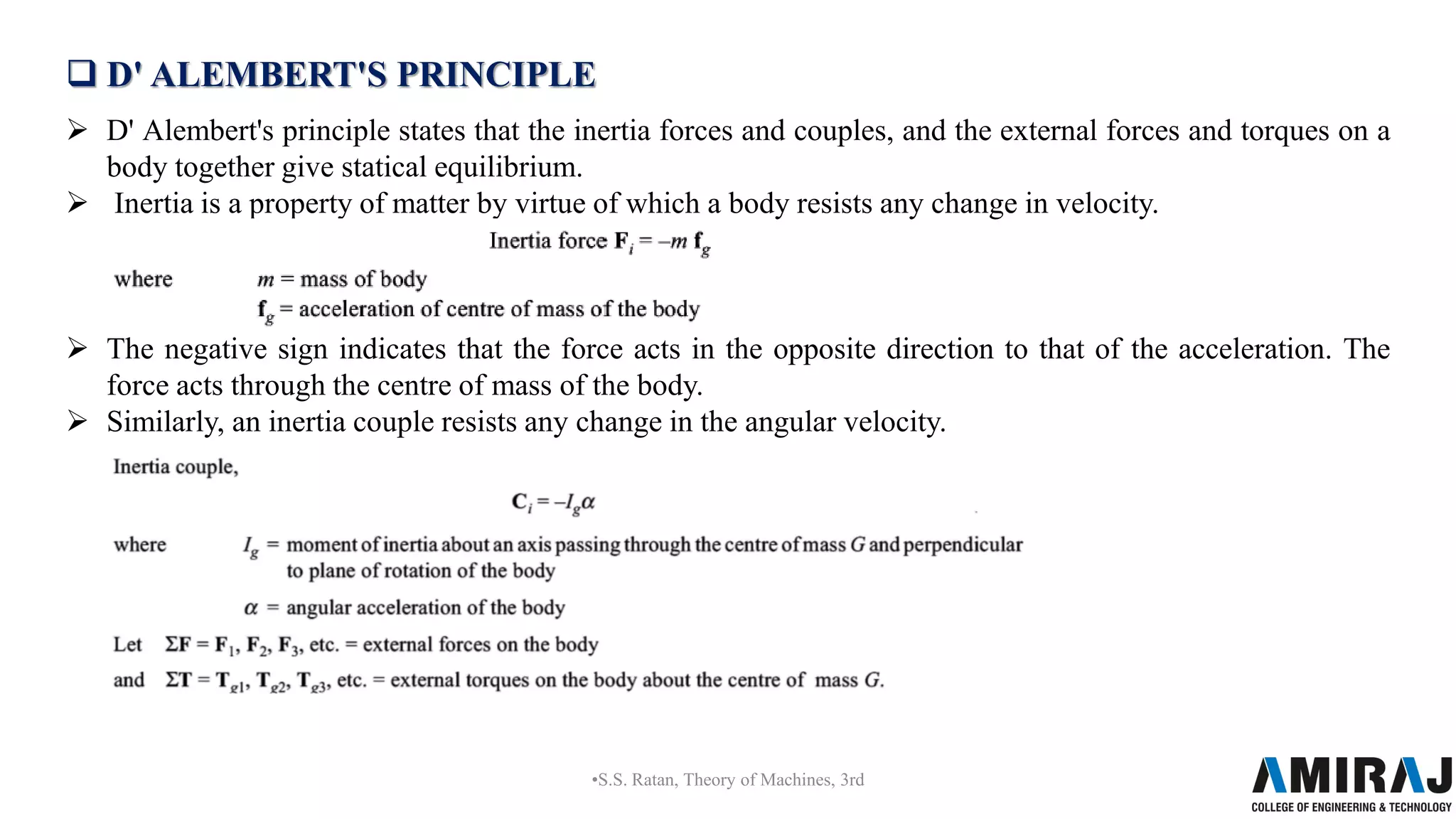
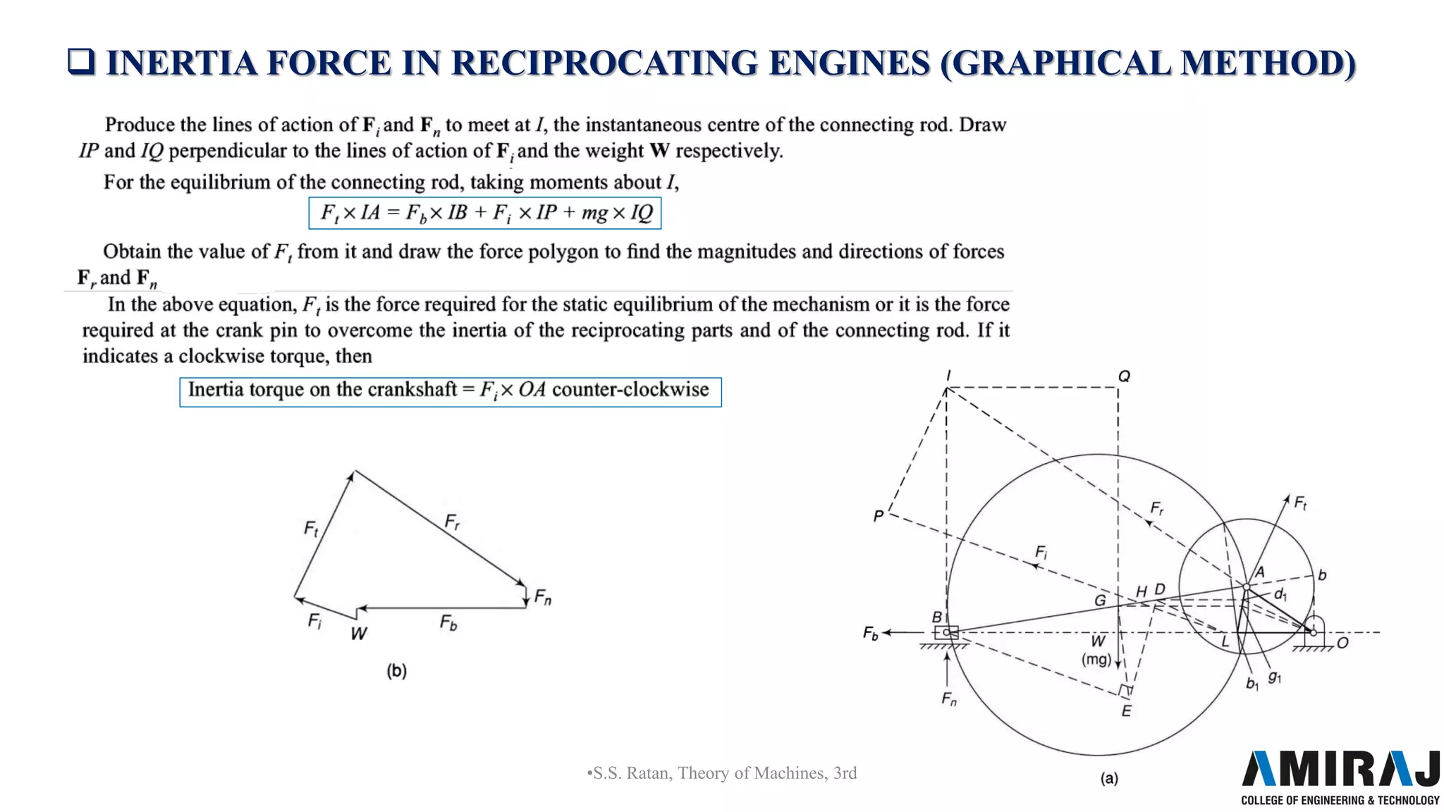
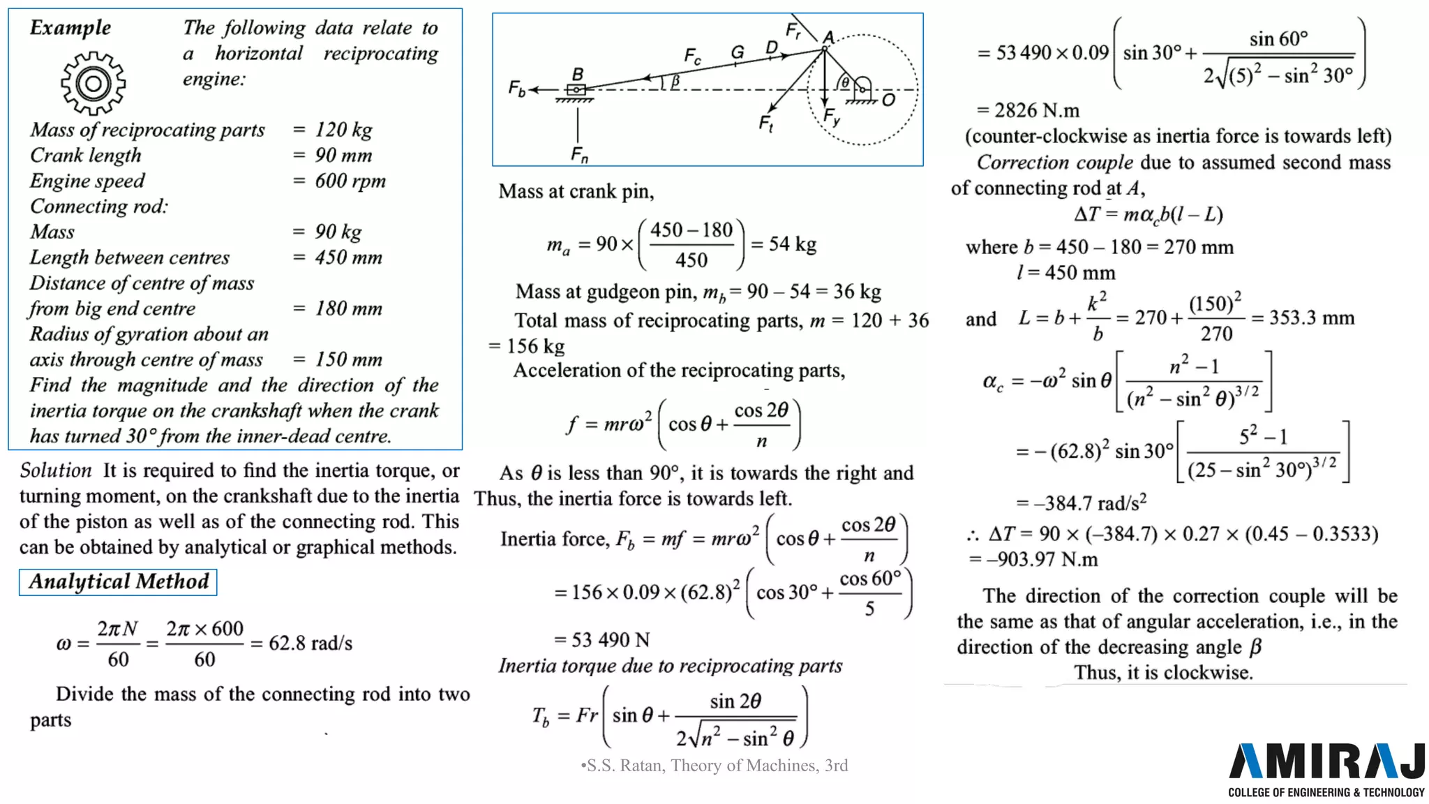
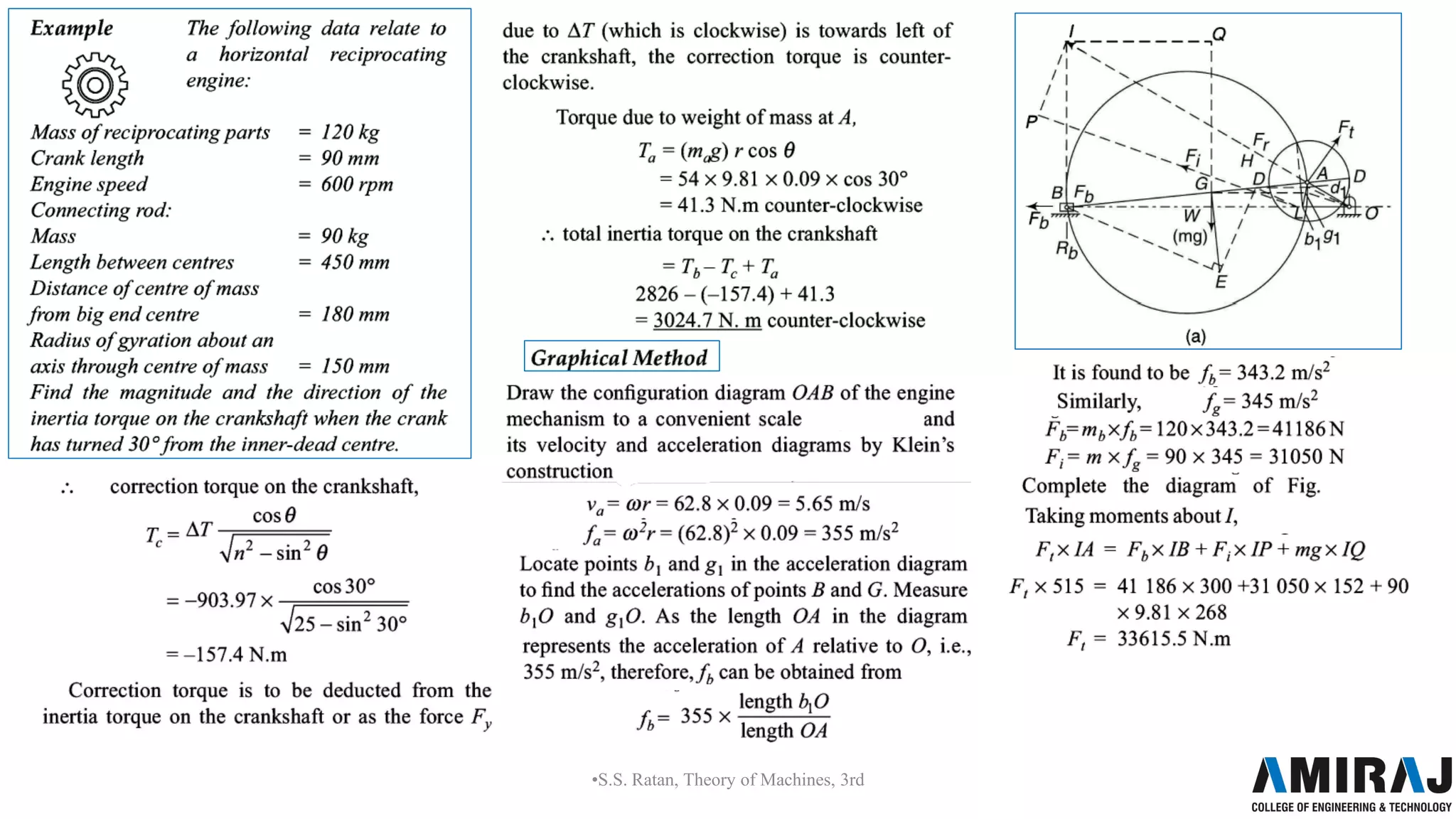
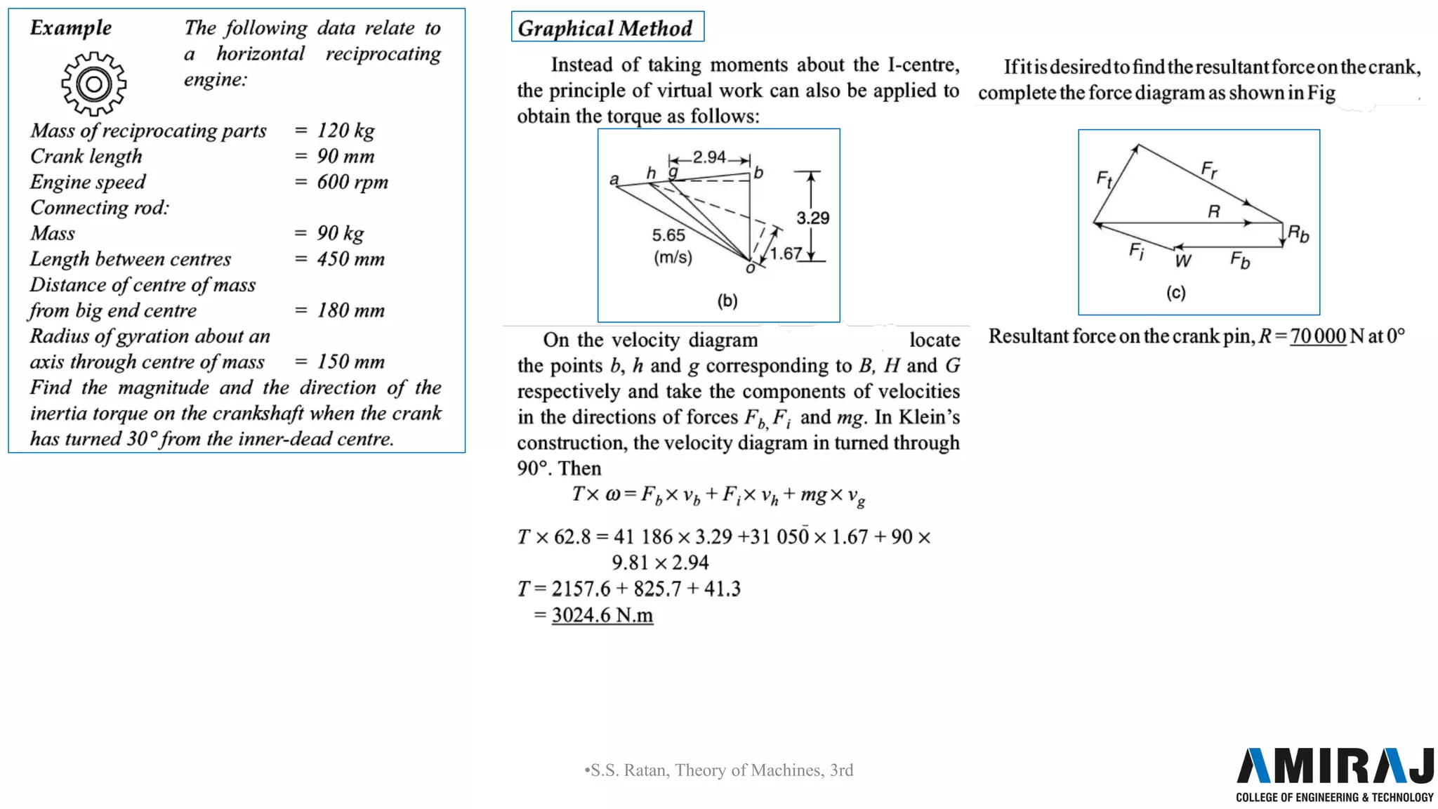
The document discusses dynamic force analysis of mechanisms. It begins by introducing the concept of dynamic forces that arise due to accelerating masses in machines. It then describes D'Alembert's principle, which states that inertia forces and external forces together produce static equilibrium. The document provides examples of applying dynamic analysis to mechanisms like four-bar linkages and slider-crank mechanisms. It also discusses determining equivalent inertia forces and torques on different components like the piston, connecting rod, and crankshaft. Graphical methods for analyzing inertia forces in reciprocating engines are also presented.
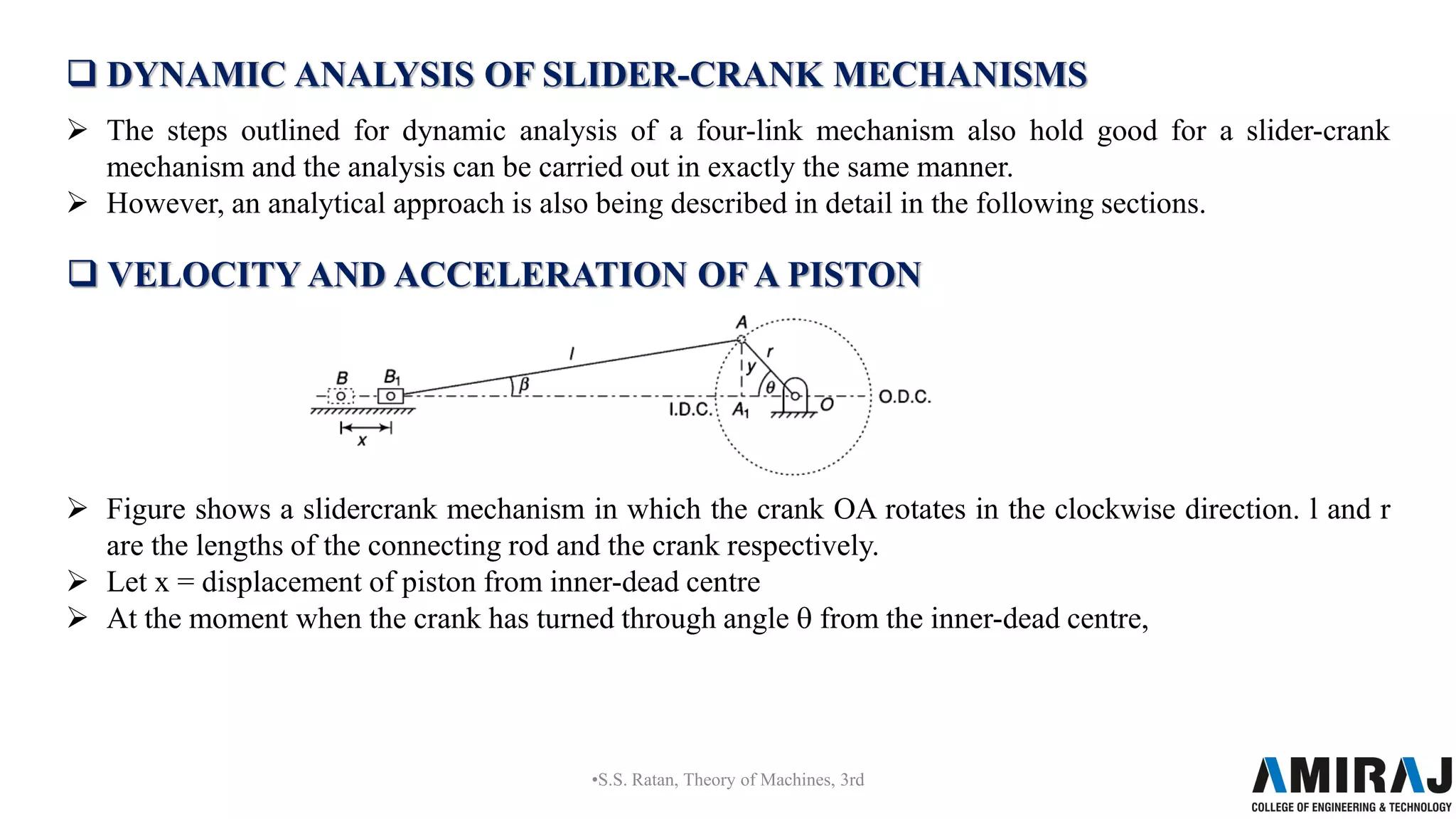

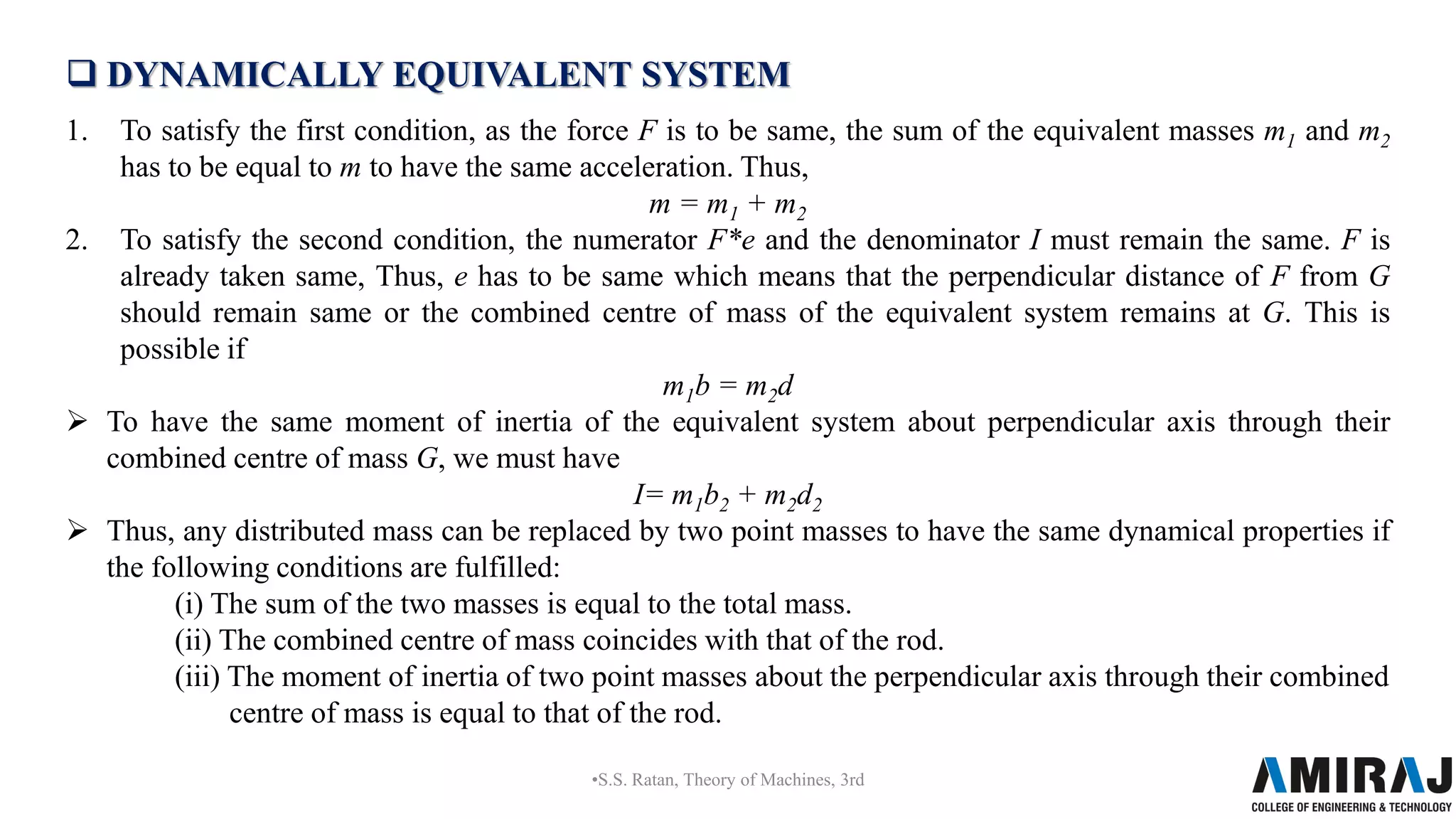
![ DYNAMICALLY EQUIVALENT SYSTEM
Figure(a) shows a rigid body of mass m with the
centre of mass at G. Let it be acted upon by a force F
which produces linear acceleration f of the centre of
mass as well as the angular acceleration of the body
as the force F does not pass through G.
•S.S. Ratan, Theory of Machines, 3rd
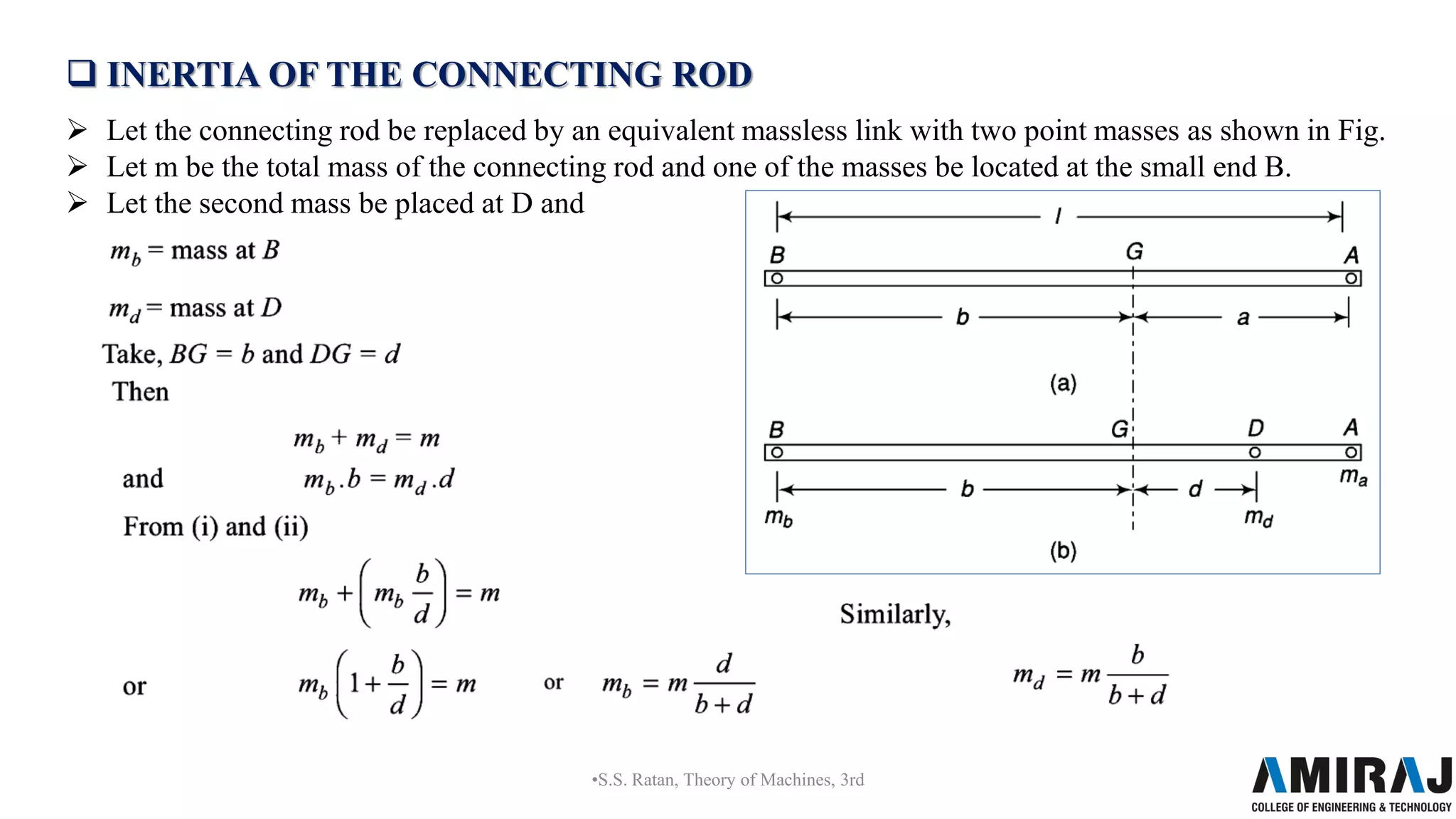
Now to have the dynamically equivalent system, let the replaced massless link [Fig. (b)] has two point
masses m1 (at B and m2 at D) at distances b and d respectively from the centre of mass G as shown in
Fig. (b).](https://image.slidesharecdn.com/dynamic-force-analysis-of-mechanismsppt-230131082102-56881777/75/dynamic-force-analysis-of-mechanisms-ppt-pdf-22-2048.jpg)


![Mechanics of machinery [Recovered].pptx](https://cdn.slidesharecdn.com/ss_thumbnails/mechanicsofmachineryrecovered-220808081831-415b3c97-thumbnail.jpg?width=640&height=640&fit=bounds)


