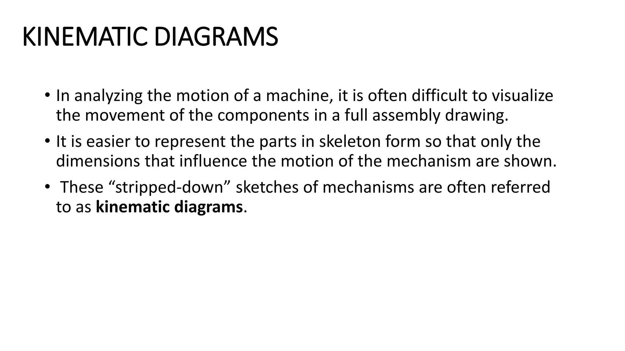
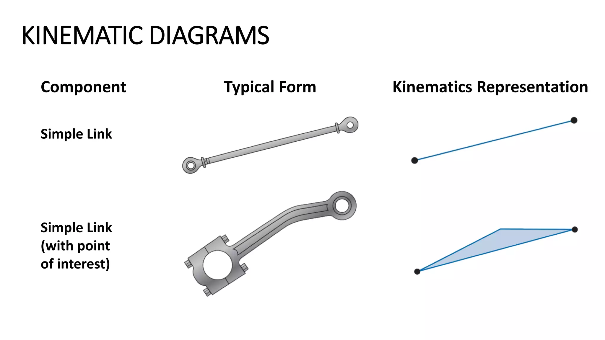
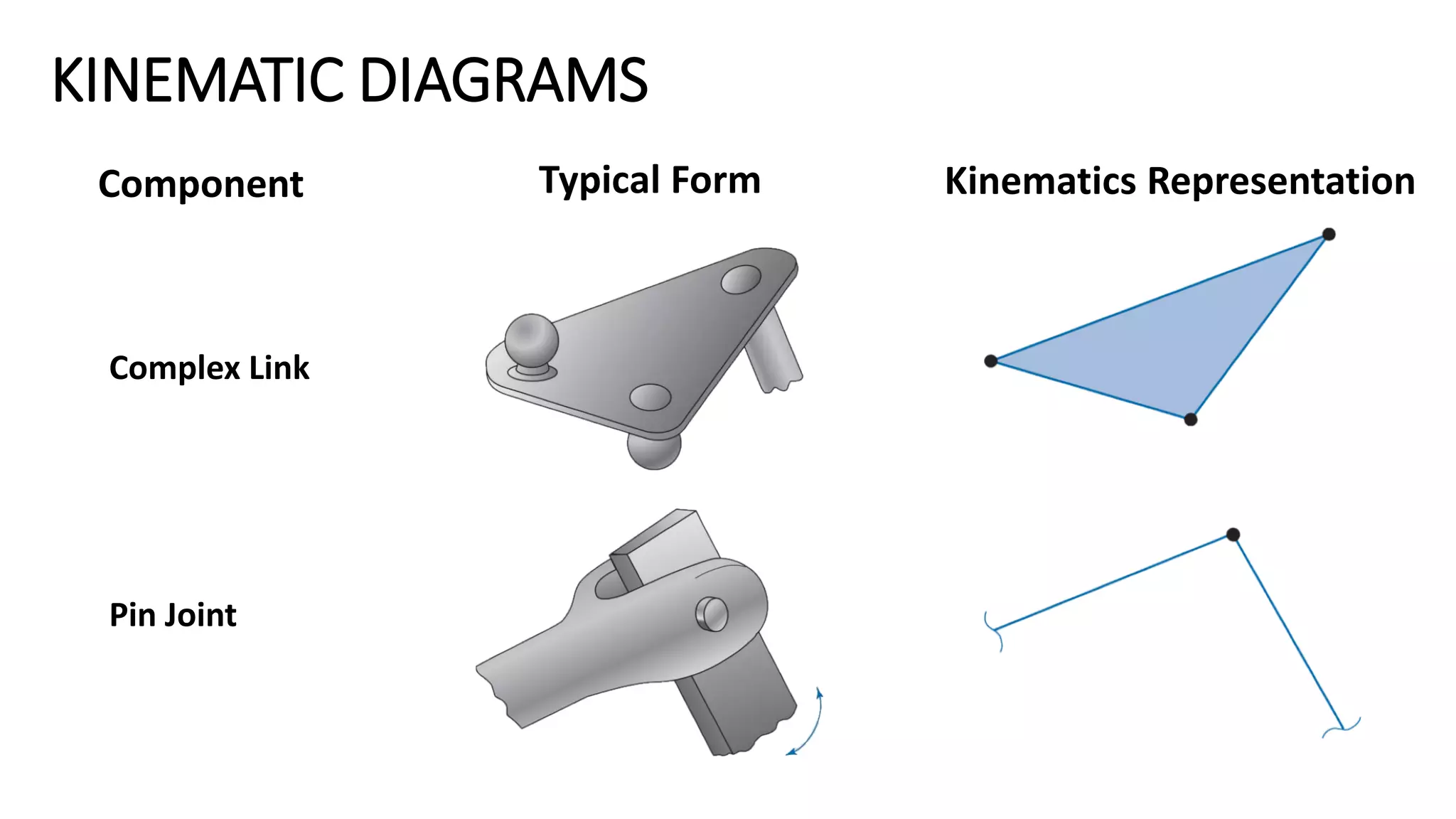
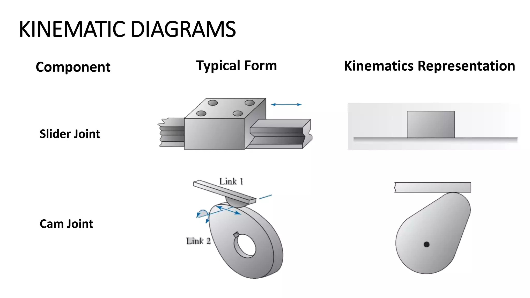
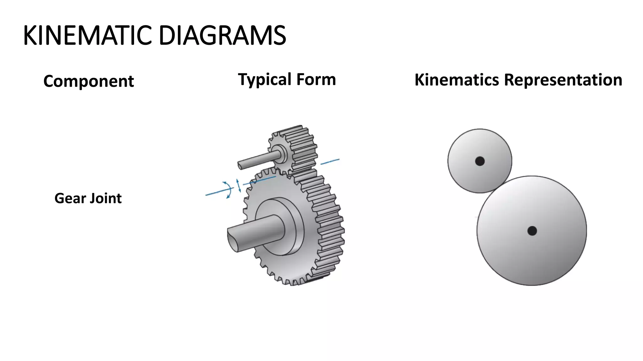
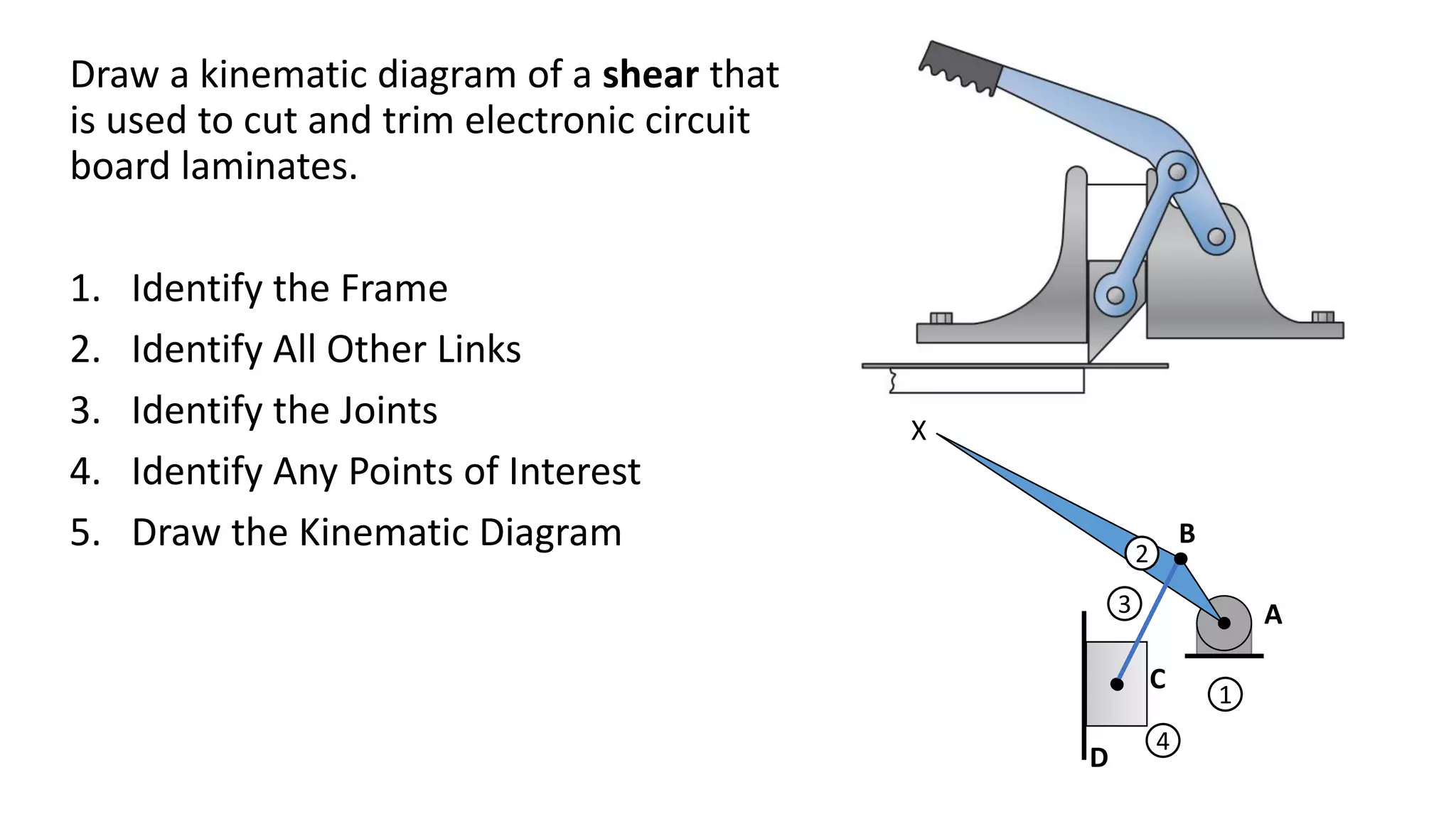
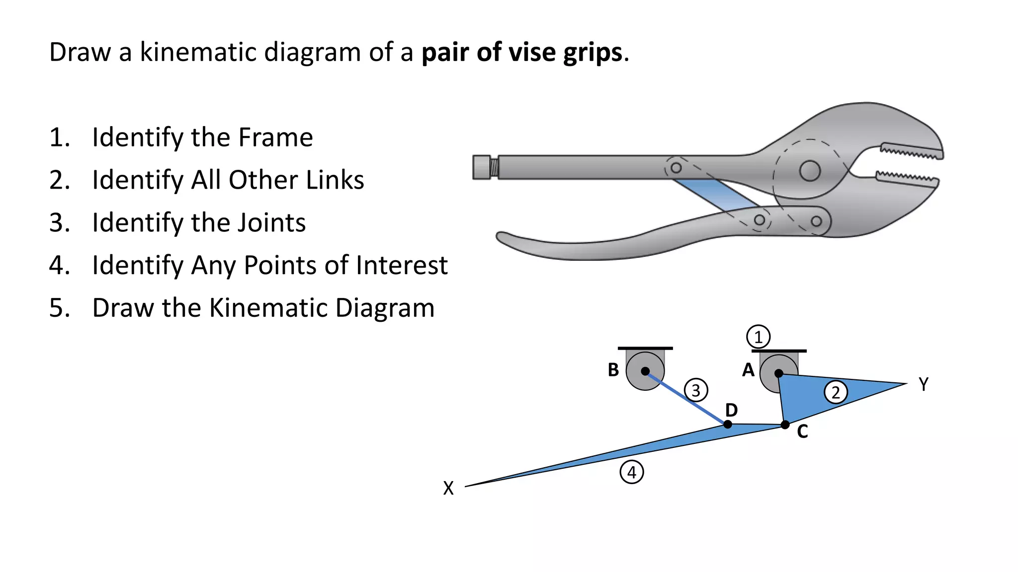
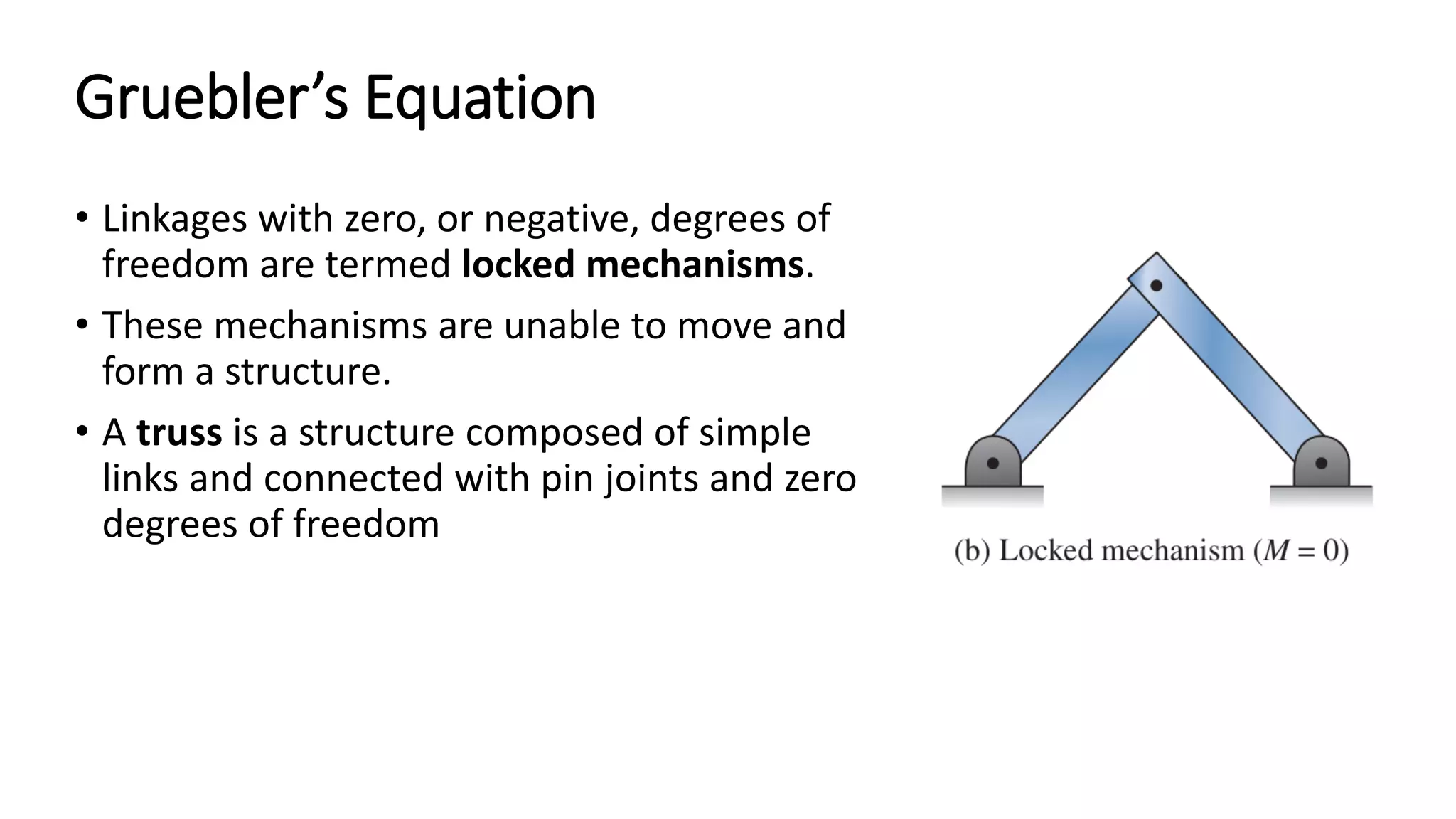
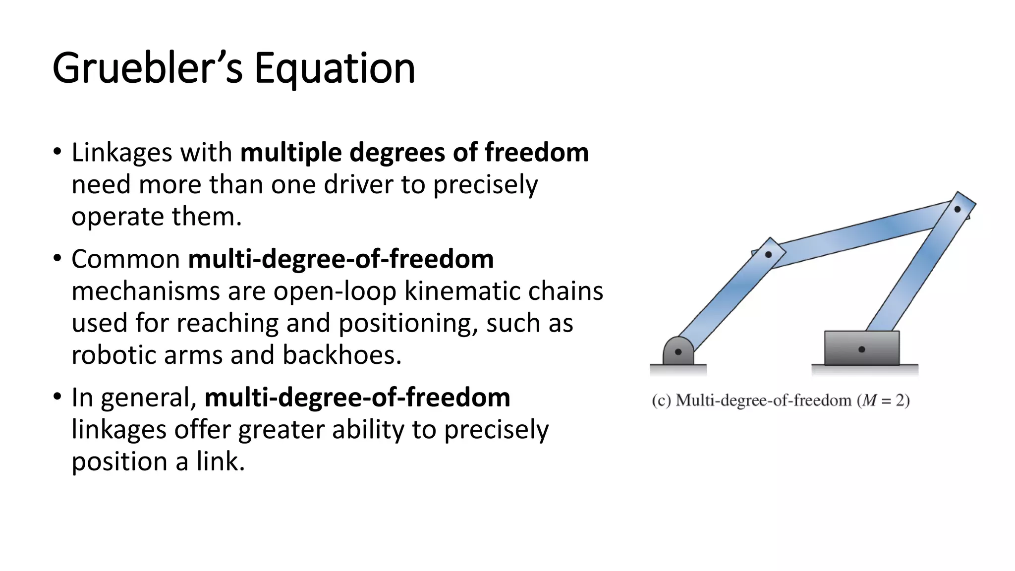
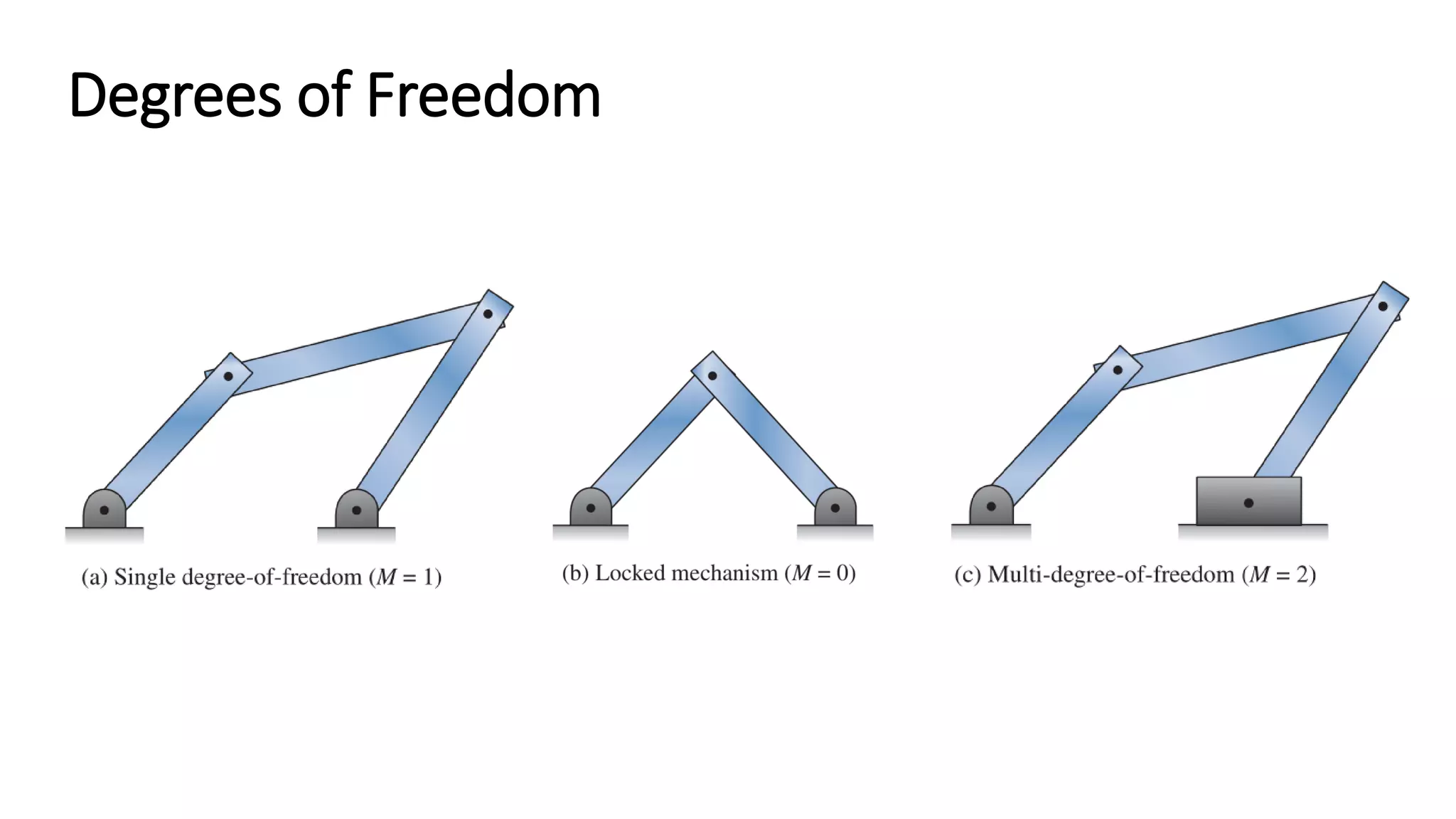
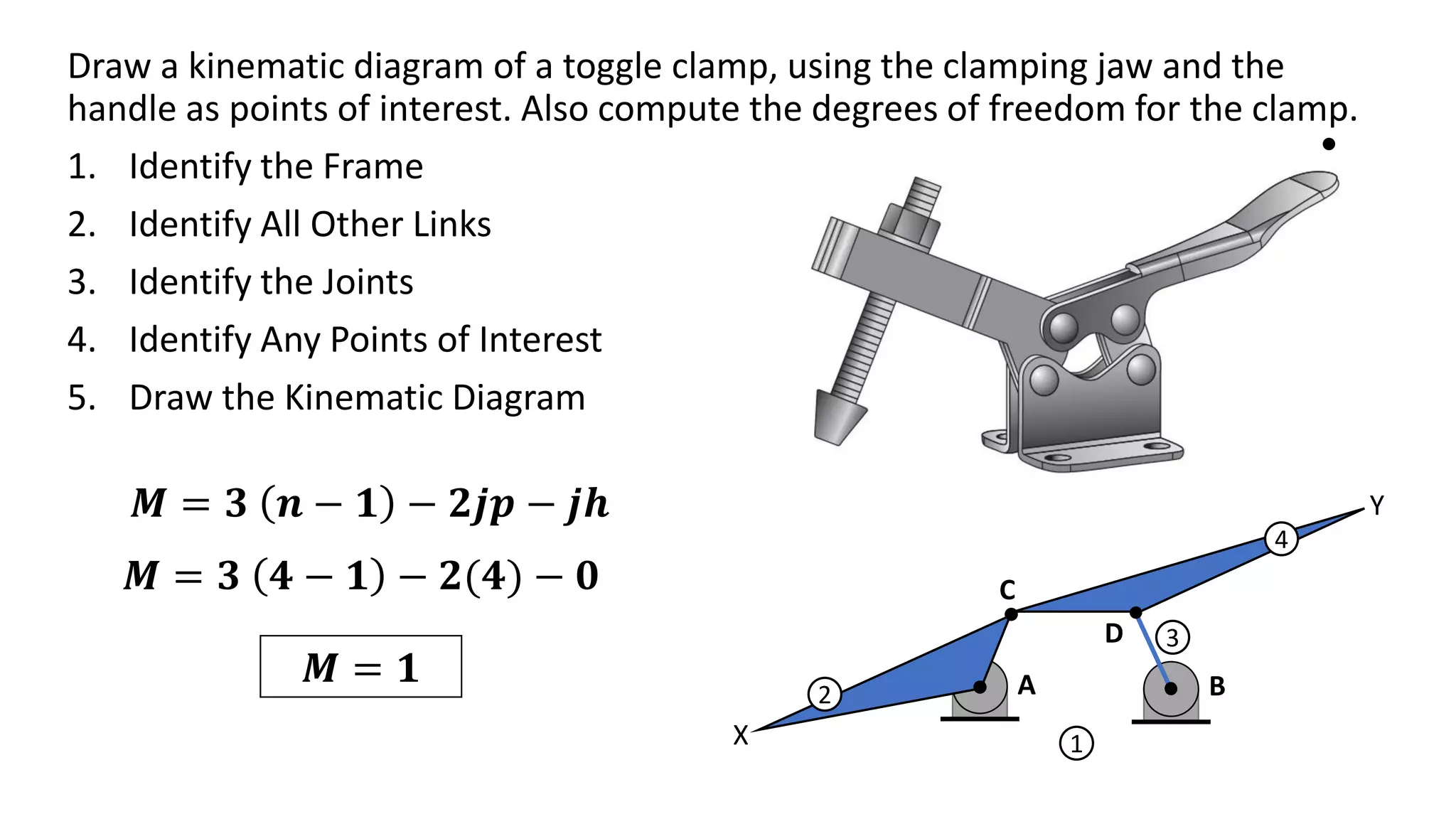
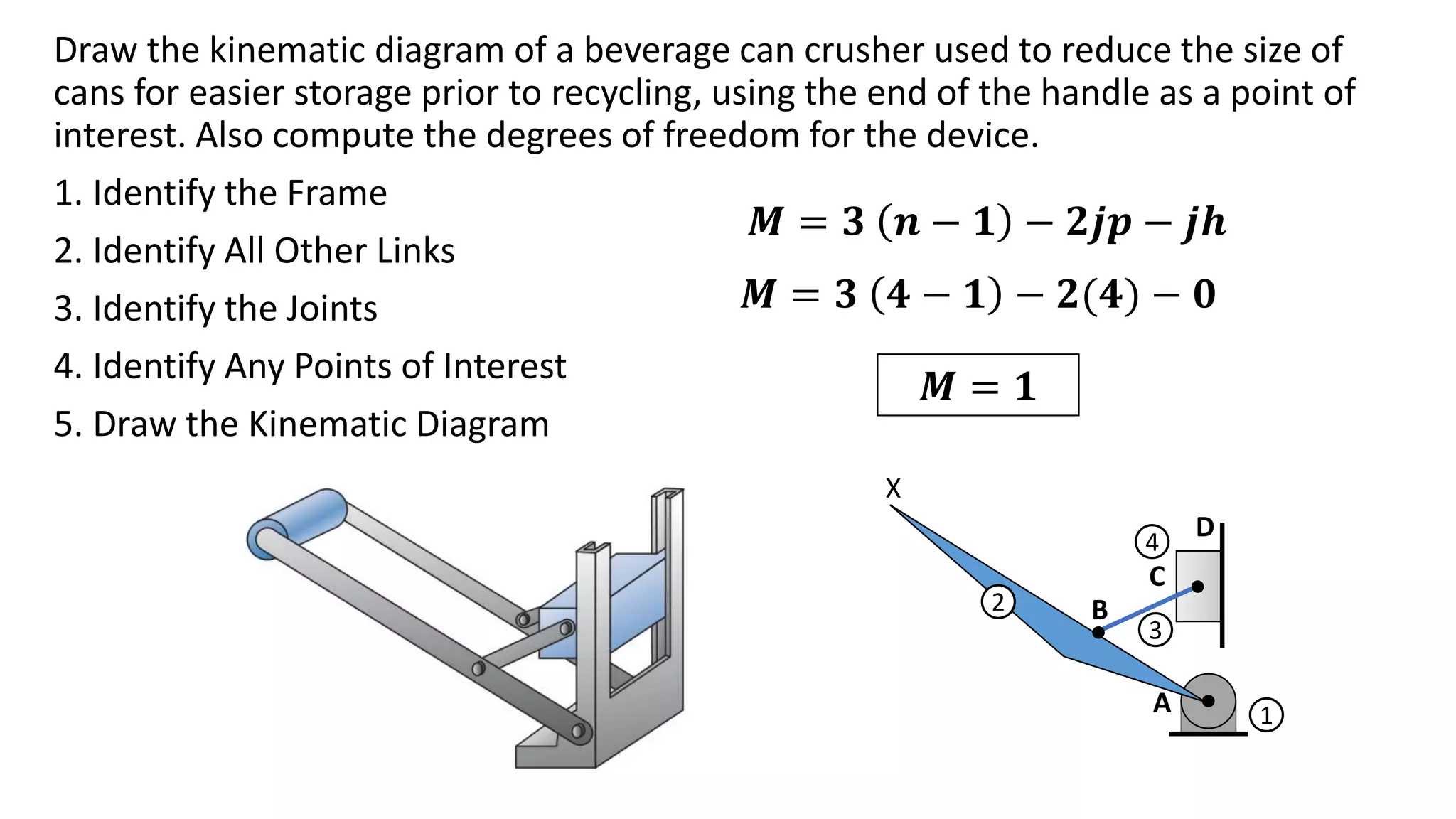
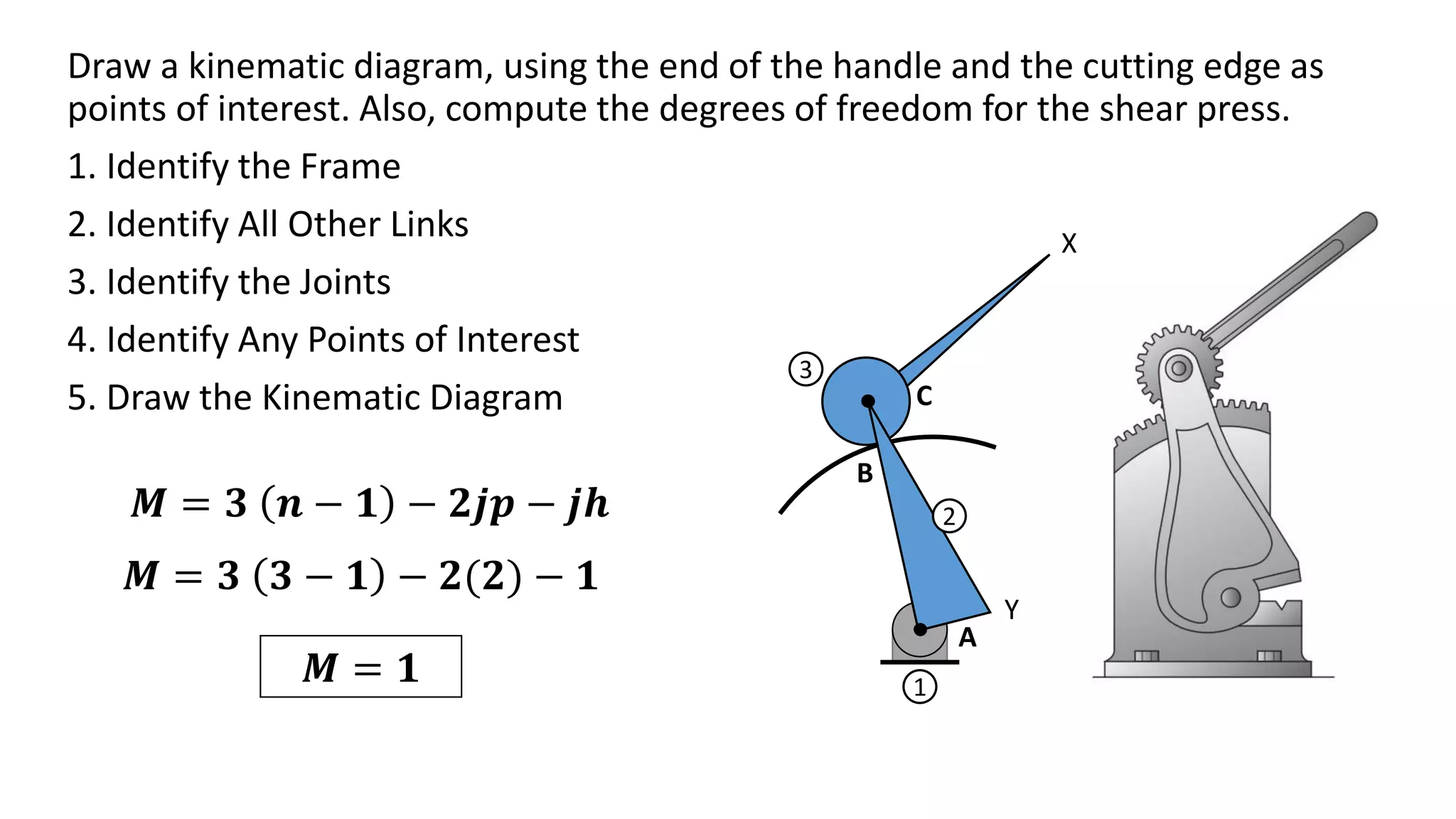
KINEMATIC DIAGRAM
• In analyzing the motion of a machine, it is often difficult to visualize
the movement of the components in a full assembly drawing.
• It is easier to represent the parts in skeleton form so that only the
dimensions that influence the motion of the mechanism are shown.
• These “stripped-down” sketches of mechanisms are often referred
to as kinematic diagrams.
KINEMATIC DIAGRAMS
KINEMATIC DIAGRAMS
Component
Simple Link
Simple Link
(with point
of interest)
Typical Form Kinematics Representation
KINEMATIC DIAGRAMS
Component
Complex Link
Pin Joint
Typical Form Kinematics Representation
KINEMATIC DIAGRAMS
Component
Slider Joint
Cam Joint
Typical Form Kinematics Representation
KINEMATIC DIAGRAMS
Component
Gear Joint
Typical Form Kinematics Representation
Draw a kinematic diagram of a shear that
is used to cut and trim electronic circuit
board laminates.
1. Identify the Frame
2. Identify All Other Links
3. Identify the Joints
4. Identify Any Points of Interest
5. Draw the Kinematic Diagram 2
1
3
4
A
B
C
D
X
Draw a kinematic diagram of a pair of vise grips.
1. Identify the Frame
2. Identify All Other Links
3. Identify the Joints
4. Identify Any Points of Interest
5. Draw the Kinematic Diagram
X
1
2
4
3
A
B
C
D
Y
KINEMATIC INVERSION
• Absolute motion is measured with respect to a stationary frame.
• Relative motion is measured for one point or link with respect to
another link.
• In some cases, the selection of a frame is arbitrary,
• As different links are chosen as a frame, the relative motion of the links
is not altered, but the absolute motion can be drastically different.
• For machines without a stationary link, relative motion is often the
desired result of kinematic analysis.
MOBILITY
• An important property in mechanism analysis is the number of degrees
of freedom of the linkage.
• The degree of freedom is the number of independent inputs required to
precisely position all links of the mechanism with respect to the ground.
• It can also be defined as the number of actuators needed to operate the
mechanism.
• A mechanism actuator could be manually moving one link to another
position, connecting a motor to the shaft of one link, or pushing a piston
of a hydraulic cylinder.
MOBILITY
• The number of degrees of freedom of a
mechanism is also called the mobility, and
it is given the symbol M.
• When the configuration of a mechanism is
completely defined by positioning one link,
that system has one degree of freedom.
• Most commercially produced mechanisms
have one degree of freedom.
• In constrast, robotic arms can have three,
or more, degrees of freedom.
Gruebler’s Equation
• Degrees of freedom for planar linkages joined with common joints
can be calculated through Gruebler’s equation:
where:
n = total number of links in the mechanism
jp = total number of primary joints (pins or sliding joints)
Jh = total number of higher-order joints (cam or gear joints)
Gruebler’s Equation
• Linkages with zero, or negative, degrees of
freedom are termed locked mechanisms.
• These mechanisms are unable to move and
form a structure.
• A truss is a structure composed of simple
links and connected with pin joints and zero
degrees of freedom
Gruebler’s Equation
• Linkages with multiple degrees of freedom
need more than one driver to precisely
operate them.
• Common multi-degree-of-freedom
mechanisms are open-loop kinematic chains
used for reaching and positioning, such as
robotic arms and backhoes.
• In general, multi-degree-of-freedom
linkages offer greater ability to precisely
position a link.
Degrees of Freedom
Draw a kinematic diagram of a toggle clamp, using the clamping jaw and the
handle as points of interest. Also compute the degrees of freedom for the clamp.
1. Identify the Frame
2. Identify All Other Links
3. Identify the Joints
4. Identify Any Points of Interest
5. Draw the Kinematic Diagram
1
2
4
3
A B
C
D
X
Y
𝑴 = 𝟑 𝒏 − 𝟏 − 𝟐𝒋𝒑 − 𝒋𝒉
𝑴 = 𝟑 𝟒 − 𝟏 − 𝟐(𝟒) − 𝟎
𝑴 = 𝟏
Draw the kinematic diagram of a beverage can crusher used to reduce the size of
cans for easier storage prior to recycling, using the end of the handle as a point of
interest. Also compute the degrees of freedom for the device.
1. Identify the Frame
2. Identify All Other Links
3. Identify the Joints
4. Identify Any Points of Interest
5. Draw the Kinematic Diagram
1
2
3
4
A
B
D
C
X
𝑴 = 𝟑 𝒏 − 𝟏 − 𝟐𝒋𝒑 − 𝒋𝒉
𝑴 = 𝟑 𝟒 − 𝟏 − 𝟐(𝟒) − 𝟎
𝑴 = 𝟏
Draw a kinematic diagram, using the end of the handle and the cutting edge as
points of interest. Also, compute the degrees of freedom for the shear press.
1. Identify the Frame
2. Identify All Other Links
3. Identify the Joints
4. Identify Any Points of Interest
5. Draw the Kinematic Diagram
1
2
3
A
C
B
X
Y
𝑴 = 𝟑 𝒏 − 𝟏 − 𝟐𝒋𝒑 − 𝒋𝒉
𝑴 = 𝟑 𝟑 − 𝟏 − 𝟐(𝟐) − 𝟏
𝑴 = 𝟏

Kinematic Diagram for pdf.pdf

  • 1.
  • 2.
    • In analyzingthe motion of a machine, it is often difficult to visualize the movement of the components in a full assembly drawing. • It is easier to represent the parts in skeleton form so that only the dimensions that influence the motion of the mechanism are shown. • These “stripped-down” sketches of mechanisms are often referred to as kinematic diagrams. KINEMATIC DIAGRAMS
  • 3.
    KINEMATIC DIAGRAMS Component Simple Link SimpleLink (with point of interest) Typical Form Kinematics Representation
  • 4.
    KINEMATIC DIAGRAMS Component Complex Link PinJoint Typical Form Kinematics Representation
  • 5.
    KINEMATIC DIAGRAMS Component Slider Joint CamJoint Typical Form Kinematics Representation
  • 6.
  • 7.
    Draw a kinematicdiagram of a shear that is used to cut and trim electronic circuit board laminates. 1. Identify the Frame 2. Identify All Other Links 3. Identify the Joints 4. Identify Any Points of Interest 5. Draw the Kinematic Diagram 2 1 3 4 A B C D X
  • 8.
    Draw a kinematicdiagram of a pair of vise grips. 1. Identify the Frame 2. Identify All Other Links 3. Identify the Joints 4. Identify Any Points of Interest 5. Draw the Kinematic Diagram X 1 2 4 3 A B C D Y
  • 9.
    KINEMATIC INVERSION • Absolutemotion is measured with respect to a stationary frame. • Relative motion is measured for one point or link with respect to another link. • In some cases, the selection of a frame is arbitrary, • As different links are chosen as a frame, the relative motion of the links is not altered, but the absolute motion can be drastically different. • For machines without a stationary link, relative motion is often the desired result of kinematic analysis.
  • 10.
    MOBILITY • An importantproperty in mechanism analysis is the number of degrees of freedom of the linkage. • The degree of freedom is the number of independent inputs required to precisely position all links of the mechanism with respect to the ground. • It can also be defined as the number of actuators needed to operate the mechanism. • A mechanism actuator could be manually moving one link to another position, connecting a motor to the shaft of one link, or pushing a piston of a hydraulic cylinder.
  • 11.
    MOBILITY • The numberof degrees of freedom of a mechanism is also called the mobility, and it is given the symbol M. • When the configuration of a mechanism is completely defined by positioning one link, that system has one degree of freedom. • Most commercially produced mechanisms have one degree of freedom. • In constrast, robotic arms can have three, or more, degrees of freedom.
  • 12.
    Gruebler’s Equation • Degreesof freedom for planar linkages joined with common joints can be calculated through Gruebler’s equation: where: n = total number of links in the mechanism jp = total number of primary joints (pins or sliding joints) Jh = total number of higher-order joints (cam or gear joints)
  • 13.
    Gruebler’s Equation • Linkageswith zero, or negative, degrees of freedom are termed locked mechanisms. • These mechanisms are unable to move and form a structure. • A truss is a structure composed of simple links and connected with pin joints and zero degrees of freedom
  • 14.
    Gruebler’s Equation • Linkageswith multiple degrees of freedom need more than one driver to precisely operate them. • Common multi-degree-of-freedom mechanisms are open-loop kinematic chains used for reaching and positioning, such as robotic arms and backhoes. • In general, multi-degree-of-freedom linkages offer greater ability to precisely position a link.
  • 15.
  • 16.
    Draw a kinematicdiagram of a toggle clamp, using the clamping jaw and the handle as points of interest. Also compute the degrees of freedom for the clamp. 1. Identify the Frame 2. Identify All Other Links 3. Identify the Joints 4. Identify Any Points of Interest 5. Draw the Kinematic Diagram 1 2 4 3 A B C D X Y 𝑴 = 𝟑 𝒏 − 𝟏 − 𝟐𝒋𝒑 − 𝒋𝒉 𝑴 = 𝟑 𝟒 − 𝟏 − 𝟐(𝟒) − 𝟎 𝑴 = 𝟏
  • 17.
    Draw the kinematicdiagram of a beverage can crusher used to reduce the size of cans for easier storage prior to recycling, using the end of the handle as a point of interest. Also compute the degrees of freedom for the device. 1. Identify the Frame 2. Identify All Other Links 3. Identify the Joints 4. Identify Any Points of Interest 5. Draw the Kinematic Diagram 1 2 3 4 A B D C X 𝑴 = 𝟑 𝒏 − 𝟏 − 𝟐𝒋𝒑 − 𝒋𝒉 𝑴 = 𝟑 𝟒 − 𝟏 − 𝟐(𝟒) − 𝟎 𝑴 = 𝟏
  • 18.
    Draw a kinematicdiagram, using the end of the handle and the cutting edge as points of interest. Also, compute the degrees of freedom for the shear press. 1. Identify the Frame 2. Identify All Other Links 3. Identify the Joints 4. Identify Any Points of Interest 5. Draw the Kinematic Diagram 1 2 3 A C B X Y 𝑴 = 𝟑 𝒏 − 𝟏 − 𝟐𝒋𝒑 − 𝒋𝒉 𝑴 = 𝟑 𝟑 − 𝟏 − 𝟐(𝟐) − 𝟏 𝑴 = 𝟏