This document provides instruction on determining velocities and angular velocities in mechanisms using the relative velocity method. It contains 5 problems:
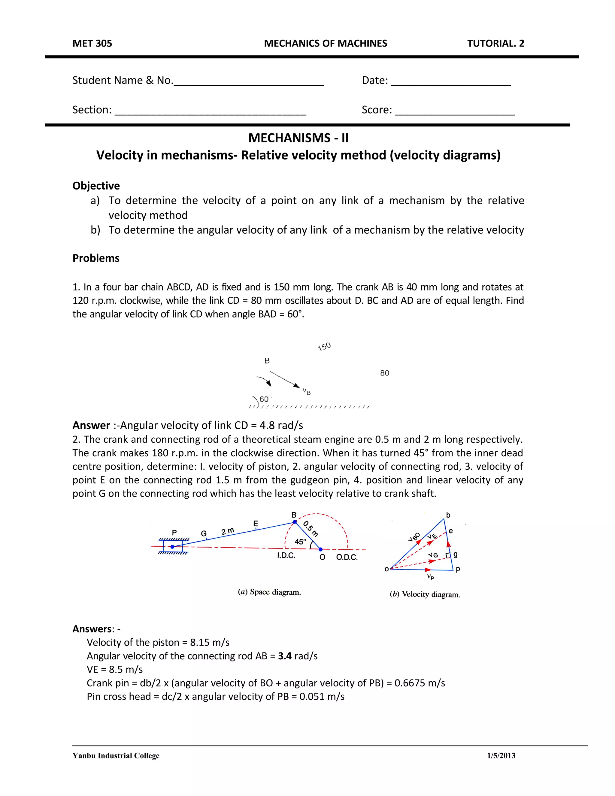
1) Finding the angular velocity of a link in a 4-bar chain mechanism.
2) Determining velocities in a steam engine mechanism including the piston, connecting rod, and points on the connecting rod.
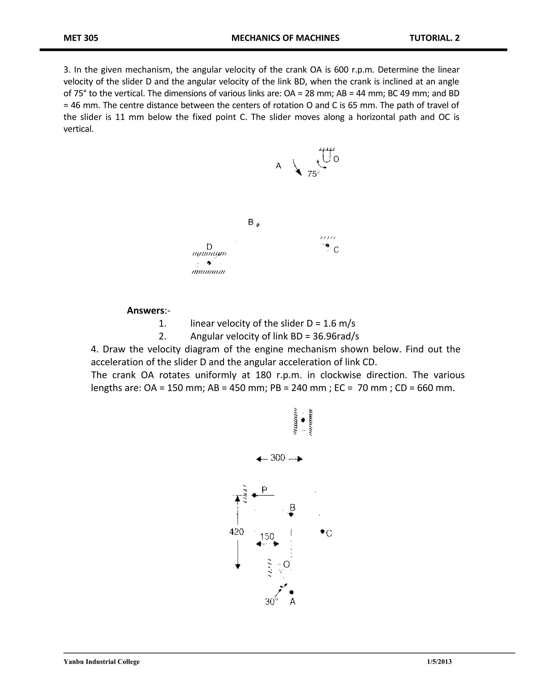
3) Finding the linear velocity of a slider and angular velocity of a link in a mechanism when the crank is at a specified angle.
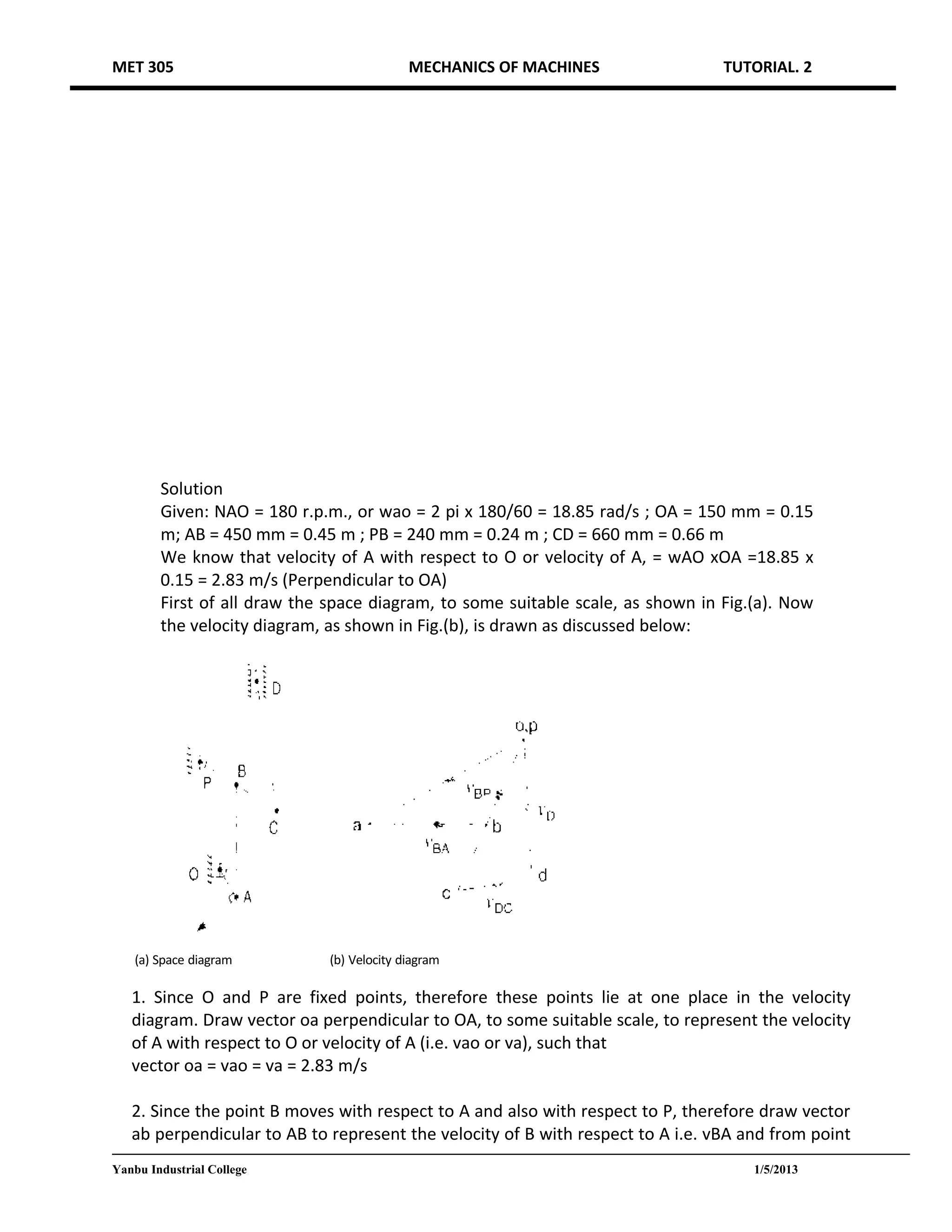
4) Drawing a velocity diagram for an engine mechanism and determining the slider and link accelerations.
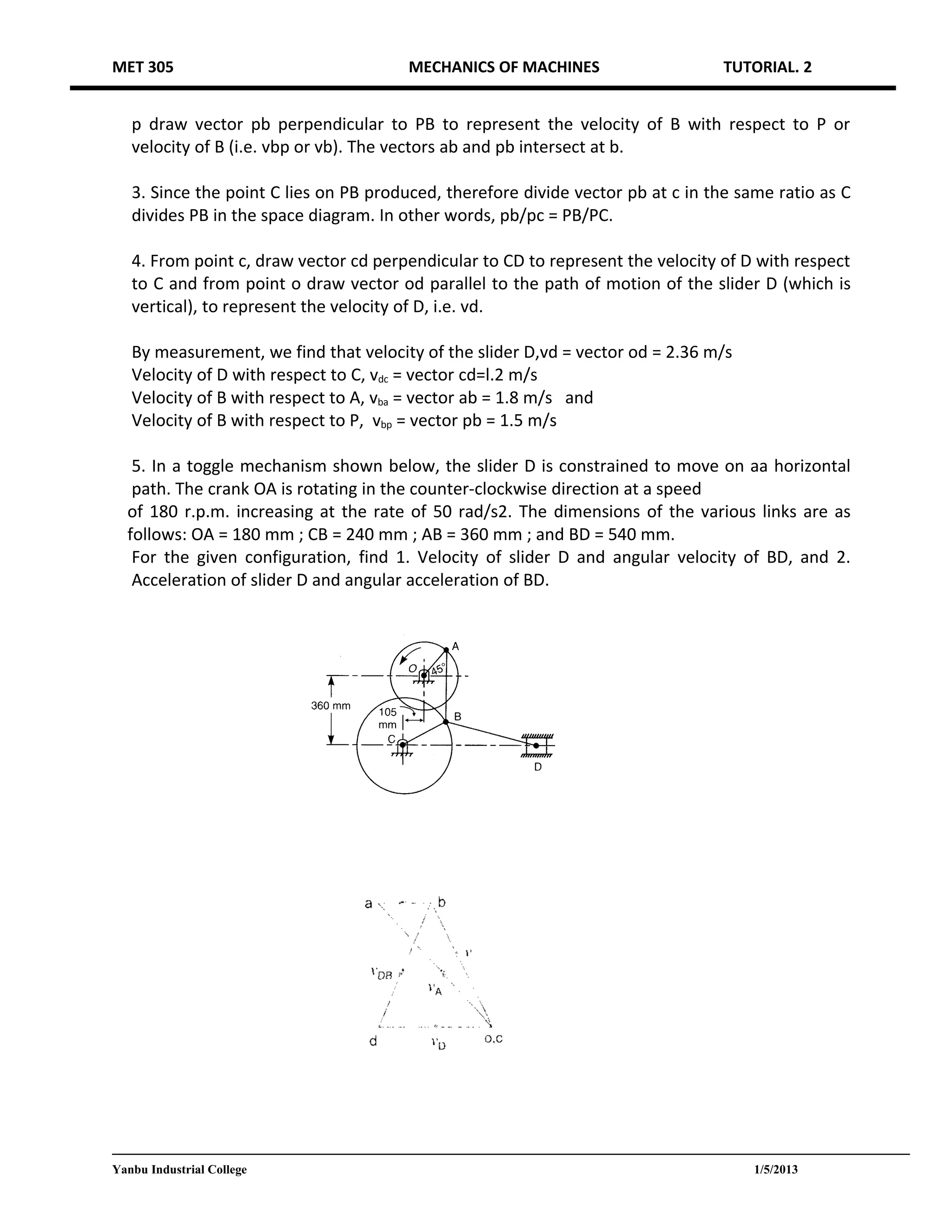
5) Determining velocities and angular velocities, and then accelerations, in a toggle mechanism where the crank speed is increasing.