Slider Crank Mechanism for Four bar linkage

the slider crank mechanism is a particular four bar linkage configuration that exhibits both linear and rotational motion simultaneously. This mechanism is frequently utilized in undergraduate engineering courses to investigate machine kinematics and resulting dynamic forces. The position, velocity, acceleration and shaking forces generated by a slider crank mechanism during operation can be determined analytically. Certain factors are often neglected from analytical calculations, causing results to differ from experimental data. The study of these slight variances produces useful insight. The following report details the successful design, fabrication and testing of a pneumatically powered slider crank mechanism for the purpose of classroom demonstration and experimentation. Transducers mounted to the mechanism record kinematic and dynamic force data during operation, which can then be compared to analytical values. The mechanism is capable of operating in balanced and unbalanced configurations so that the magnitude of shaking forces can be compared. The engine was successfully manufactured and operates as intended. Data recorded by the device's accelerometers is comparable to calculated values of acceleration and shaking force.
![Slider Crank Mechanism for Four bar linkage
(IJSRD/Vol. 1/Issue 9/2013/0084)
All rights reserved by www.ijsrd.com 2024
3) Third inversion (i.e., Oscillating cylinder engine and
crank & slotted lever mechanism)
4) Fourth inversion (Hand pump)
II. OUTCOMES
The kinematic motion of the slider in the slider-crank
mechanism can be ex-pressed in terms of the lengths of the
crank and the conrod, and the angular displacement of the
crankshaft. The experimental measurements of piston dis-
placement agree with the predictions of a theoretical model
of the piston motion to within 33% of the stroke of the
piston. In the present experiment, an o Æset between the
theoretical and experimental values for piston displacement
was also observed. This was attributed to the incorrect
setting of the zero angle of the protractor that measures
crank angle. This oÆset is estimated as 4 the inlet valve was
open during the intake stroke and the exhaust valve was
open during the exhaust stroke. The opening range of both
valves extended past the top-dead-center positions for their
respective strokes. Near top dead center between the exhaust
and intake strokes, both valves were open for approximately
+20 and angular rotation of the crankshaft. The increased
range of valve opening allows more air to move in during
the intake stroke and out during the exhaust stroke.
ACKNOWLEDGEMENTS
The author would like to thanks D.K. PANDEY,
Department Head, RMS Polytechnic-Bakrol for his
guidance during the project.
REFERENCES
[1] T. W. Ng. A slider-crank experiment to determine the
action of static forces. International Journal of
Mechanical Engineering Education Volume 31 Number
4 October 2003.
[2] Selçuk Erkaya, Sükrü Su, and Ibrahim Uzmay.
Dynamic analysis of a slider – crank mechanism with
eccentric connector and planetary gears Mechanism and
Machine Theory 42 (2007) 393– 408.
[3] Rong-Fong Fung, Chin-Lung Chiang and Shin-Jen
Chen. Dynamic modelling of an intermittent slider-
crank mechanism. Applied matehmatcical modelling 33
(2009) 2411-2420
[4] ADAMS Software, MSc
Softwares,http://www.mscsoftware.com/Products/CAE-
Tools/Adams.aspx
[5] Mohammad Rajbarkohan, Mansour Rasekh, Abdol
Hamid Hosani, Mohammad Reza Aside, Kinematics
and kinetic analysis of slider crank mechanism in Otto
linear four cylinder Z24 engine. Journal of mechanical
engineering research vol3 (3) page 85-95, March 2011.
[6] Ahmah A. Shabana, Dynamics of Multibody Systems,
published by press syndicate of university of
Cambridge, Cambridge University Press.](data:image/gif;base64,R0lGODlhAQABAIAAAAAAAP///yH5BAEAAAAALAAAAAABAAEAAAIBRAA7)
Recommended
More Related Content
What's hot
What's hot (20)
Viewers also liked
Viewers also liked (20)
Similar to Slider Crank Mechanism for Four bar linkage
Similar to Slider Crank Mechanism for Four bar linkage (20)
More from ijsrd.com
More from ijsrd.com (20)
Recently uploaded
Recently uploaded (20)
Slider Crank Mechanism for Four bar linkage
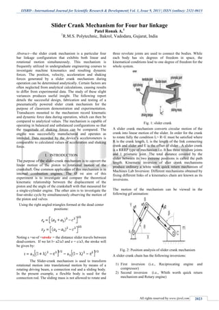
- 1. IJSRD - International Journal for Scientific Research & Development| Vol. 1, Issue 9, 2013 | ISSN (online): 2321-0613 All rights reserved by www.ijsrd.com 2023 Slider Crank Mechanism for Four bar linkage Patel Ronak A.1 1 R.M.S. Polytechnic, Bakrol, Vadodara, Gujarat, India Abstract—the slider crank mechanism is a particular four bar linkage configuration that exhibits both linear and rotational motion simultaneously. This mechanism is frequently utilized in undergraduate engineering courses to investigate machine kinematics and resulting dynamic forces. The position, velocity, acceleration and shaking forces generated by a slider crank mechanism during operation can be determined analytically. Certain factors are often neglected from analytical calculations, causing results to differ from experimental data. The study of these slight variances produces useful insight. The following report details the successful design, fabrication and testing of a pneumatically powered slider crank mechanism for the purpose of classroom demonstration and experimentation. Transducers mounted to the mechanism record kinematic and dynamic force data during operation, which can then be compared to analytical values. The mechanism is capable of operating in balanced and unbalanced configurations so that the magnitude of shaking forces can be compared. The engine was successfully manufactured and operates as intended. Data recorded by the device’s accelerometers is comparable to calculated values of acceleration and shaking force. I. INTRODUCTION The purpose of the slider-crank mechanism is to convert the linear motion of the piston to rotational motion of the crankshaft. One common application of this mechanism is in internal combustion engines. The Ø rst aim of this experiment is to investigate and compare the theoretical kinematic relationship between the displacement of the piston and the angle of the crankshaft with that measured for a single-cylinder engine. The other aim is to investigate the four-stroke cycle by simultaneously observing the motion of the piston and valves Using the right angled triangles formed at the dead center positions: Noting s =se-sf =stroke = the distance slider travels between dead-centers. If we let l= a2/a3 and e = c/a3, the stroke will be given by: The Slider-crank mechanism is used to transform rotational motion into translational motion by means of a rotating driving beam, a connection rod and a sliding body. In the present example, a flexible body is used for the connection rod. The sliding mass is not allowed to rotate and three revolute joints are used to connect the bodies. While each body has six degrees of freedom in space, the kinematical conditions lead to one degree of freedom for the whole system. Fig. 1: slider crank A slider crank mechanism converts circular motion of the crank into linear motion of the slider. In order for the crank to rotate fully the condition L> R+E must be satisfied where R is the crank length, L is the length of the link connecting crank and slider and E is the offset of slider . A slider crank is a RRRP type of mechanism i.e. It has three revolute joints and 1 prismatic joint. The total distance covered by the slider between its two extreme positions is called the path length. Kinematic inversion of slier crank mechanisms produce ordinary a white work quick return mechanism of Machines Lab Inversion: Different mechanisms obtained by fixing different links of a kinematics chain are known as its inversions. The motion of the mechanism can be viewed in the following gif animation: Fig. 2: Position analysis of slider crank mechanism A slider crank chain has the following inversions: 1) First inversion (i.e., Reciprocating engine and compressor) 2) Second inversion (i.e., Whith worth quick return mechanism and Rotary engine)
- 2. Slider Crank Mechanism for Four bar linkage (IJSRD/Vol. 1/Issue 9/2013/0084) All rights reserved by www.ijsrd.com 2024 3) Third inversion (i.e., Oscillating cylinder engine and crank & slotted lever mechanism) 4) Fourth inversion (Hand pump) II. OUTCOMES The kinematic motion of the slider in the slider-crank mechanism can be ex-pressed in terms of the lengths of the crank and the conrod, and the angular displacement of the crankshaft. The experimental measurements of piston dis- placement agree with the predictions of a theoretical model of the piston motion to within 33% of the stroke of the piston. In the present experiment, an o Æset between the theoretical and experimental values for piston displacement was also observed. This was attributed to the incorrect setting of the zero angle of the protractor that measures crank angle. This oÆset is estimated as 4 the inlet valve was open during the intake stroke and the exhaust valve was open during the exhaust stroke. The opening range of both valves extended past the top-dead-center positions for their respective strokes. Near top dead center between the exhaust and intake strokes, both valves were open for approximately +20 and angular rotation of the crankshaft. The increased range of valve opening allows more air to move in during the intake stroke and out during the exhaust stroke. ACKNOWLEDGEMENTS The author would like to thanks D.K. PANDEY, Department Head, RMS Polytechnic-Bakrol for his guidance during the project. REFERENCES [1] T. W. Ng. A slider-crank experiment to determine the action of static forces. International Journal of Mechanical Engineering Education Volume 31 Number 4 October 2003. [2] Selçuk Erkaya, Sükrü Su, and Ibrahim Uzmay. Dynamic analysis of a slider – crank mechanism with eccentric connector and planetary gears Mechanism and Machine Theory 42 (2007) 393– 408. [3] Rong-Fong Fung, Chin-Lung Chiang and Shin-Jen Chen. Dynamic modelling of an intermittent slider- crank mechanism. Applied matehmatcical modelling 33 (2009) 2411-2420 [4] ADAMS Software, MSc Softwares,http://www.mscsoftware.com/Products/CAE- Tools/Adams.aspx [5] Mohammad Rajbarkohan, Mansour Rasekh, Abdol Hamid Hosani, Mohammad Reza Aside, Kinematics and kinetic analysis of slider crank mechanism in Otto linear four cylinder Z24 engine. Journal of mechanical engineering research vol3 (3) page 85-95, March 2011. [6] Ahmah A. Shabana, Dynamics of Multibody Systems, published by press syndicate of university of Cambridge, Cambridge University Press.