Download as PDF, PPTX
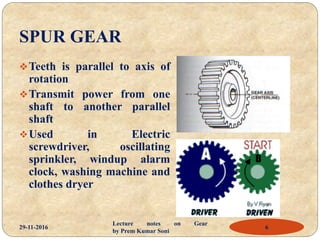
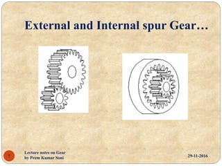
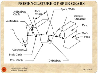
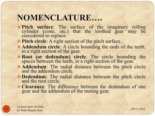
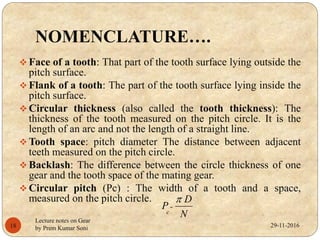
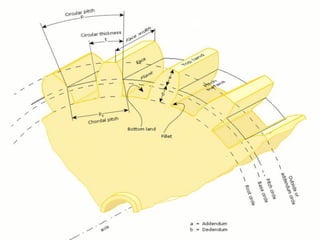


The document is a set of lecture notes on gears that discusses various topics including: - Types of gears like spur gears, helical gears, bevel gears, and worm gears. - Gear terminology like pitch circle, addendum, dedendum, and module. - Applications of different gears in devices like electric screwdrivers, steering systems, and material handling equipment. - Factors that affect gear performance like backlash, which is the play between meshing gear teeth that can cause imprecision.


