Downloaded 238 times
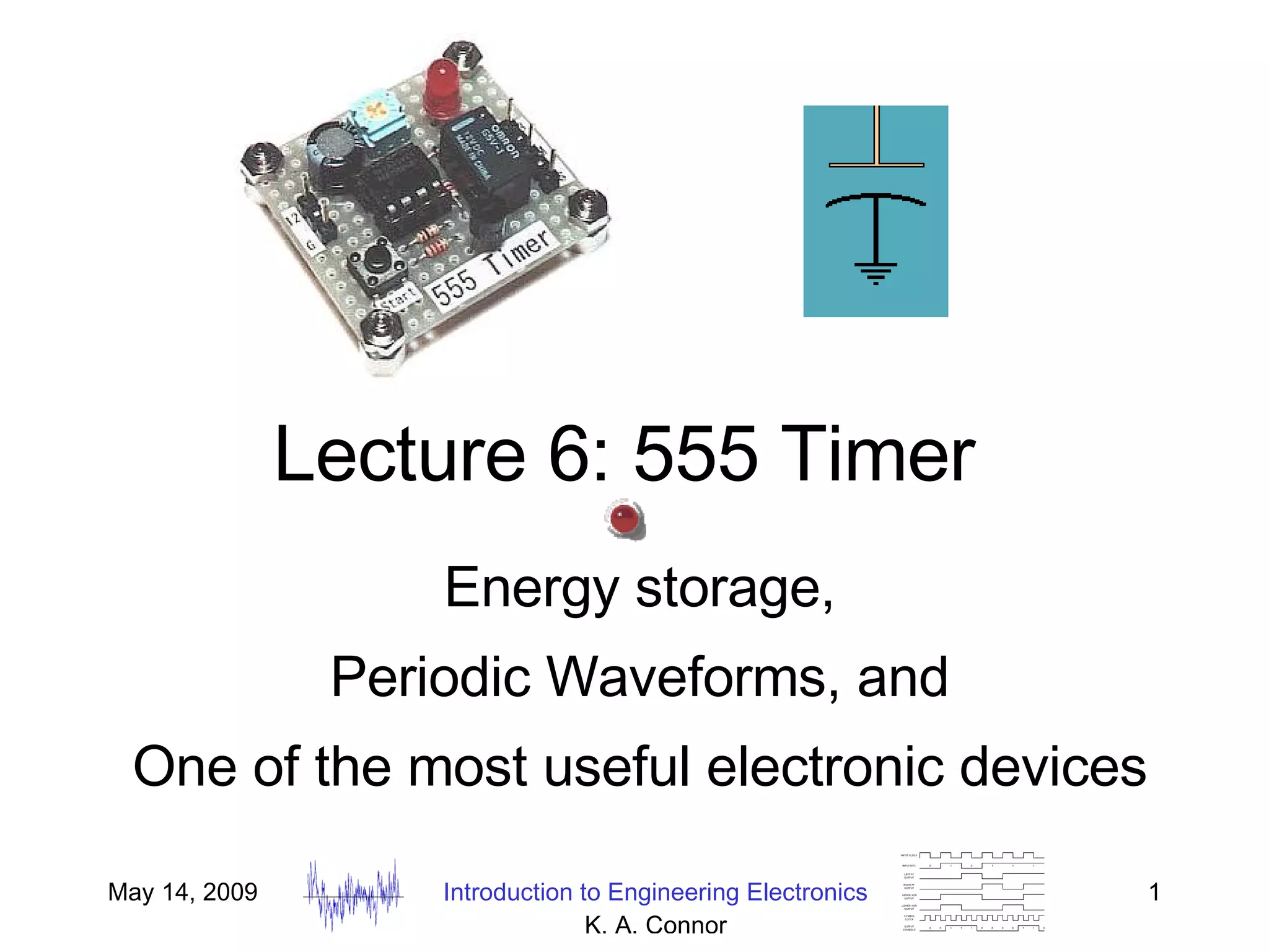


This document discusses periodic waveforms and examples of periodic motion including pendulums, bouncing balls, and vibrating strings. It then summarizes how a 555 timer circuit can produce a steady train of pulses using a capacitor and resistors, and describes applications of the 555 timer such as producing audio signals and LED lighting. The document also discusses using a tank circuit with an inductor and capacitor to produce oscillating signals.