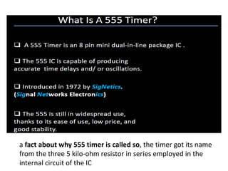
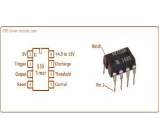
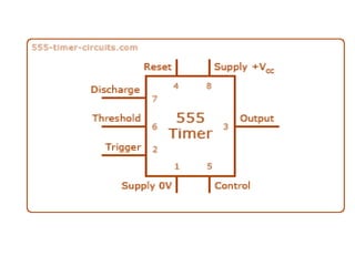
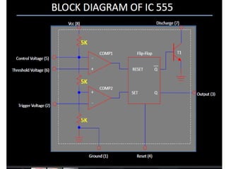
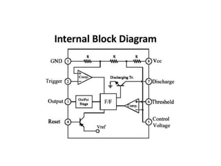
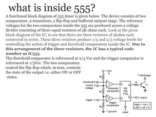
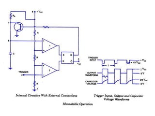
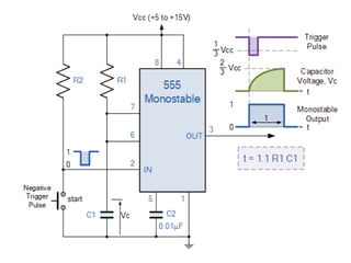
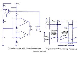
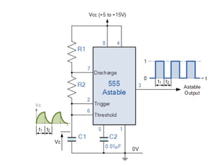
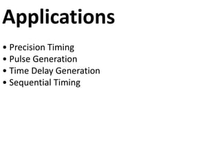
SlideShare a Scribd company logo
TIMER IC-555
a fact about why 555 timer is called so, the timer got its name
from the three 5 kilo-ohm resistor in series employed in the
internal circuit of the IC
IMAGINATION OF TIMER CIRCUIT ON PCB
TIMMER IN IC FORM
Basics Concepts:
· Comparator: The Comparator are the basic electronic
component which compares the two input voltages i.e. between
the inverting (-) and the non-inverting (+) input and if the non-
inverting input is more than the inverting input then the output of
the comparator is high. Also the input resistance of an ideal
comparator is infinite.
· Voltage Divider: As we know that the input resistance of the
comparators is infinite hence the input voltage is divided equally
between the three resistors. The value being Vin/3 across each
resistor.
· Flip/Flop: Flip/Flop is a memory element of Digital-electronics.
The output (Q) of the flip/flop is ‘high’ if the input at ‘S’ terminal is
‘high’ and ‘R’ is at ‘Low’ and the output (Q) is ‘low’ when the input
at ‘S’ is ‘low’ and at ‘R’ is high.
what is inside 555?
A functional block diagram of 555 timer is given below. The device consists of two
comparators ,2 transistors, a flip-flop and buffered outputs stage. The reference
voltages for the two comparators inside the 555 are produced across a voltage
divider consisting of three equal resistors of 5K ohms each. Look at the given
block diagram of the IC, to see that there are three resistors of 5kohm each
connected in series. These three resistors produce 1/3 and 2/3 voltage levels for
controlling the action of trigger and threshold comparators inside the IC. Due to
this arrangement of the three resistors, the IC has a typical code
number as IC555.
The threshold comparator is referenced at 2/3 Vcc and the trigger comparator is
referenced at 1/3Vcc. The two comparators
control the flip-flop which, in turn, controls
the state of the output i.e. either ON or OFF
states.
Pin configuration of IC 555 :
Pin-1, GROUND: It is the GROUND PIN of the IC. The negative terminal of DC
power supply or battery is connected to this pin. Note that this pin should be connected
directly to ground and NOT through any resistor or capacitor. If done so, the IC will
not function properly and may heat up and get damaged. This happens because all the
semiconductor blocks inside the IC will be raised by certain amount of stray voltage
and will damage the IC.IC 555
Pin-2, TRIGGER It is known as TRIGGER PIN. As the name suggests in triggers i.e.
starts the timing cycle of the IC. It is connected to the inverting input terminal of trigger
comparator inside the IC. It triggers when the voltage at this pin LESS THAN 1/3 of
the supply voltage (Vcc). The triggering circuit inside the IC is very sensitive and may
be accidently activated due to surrounding noise. To avoid this, the pin is always
connected to a pull-up resistor (10k-ohm), if this pin is used separately.
Pin-3, OUTPUT This is the OUTPUT PIN of the IC. It can SINK or SOURCE a
maximum current of 200mA. Sinking the current means, when the output of the IC is at
logic-0 state i.e. LOW and so it can absorb current into its output. Similarly sourcing
the current means, when the output of the IC is at logic-1 i.e. HIGH and so it can give
out current from its output.
Pin-4, RESET It is the RESET PIN of the IC. When it is connected to positive terminal
of battery, the IC works normally. However, when it is grounded (either directly or
through a maximum of 100k-ohm resistor), the IC stops its working completely and its
timing cycle stops .However in general applications, this pin is always connected to
positive terminal so that the IC works normally.
Pin-5, C. VOLTAGE This is known as the CONTROL VOLTAGE pin. The 2/3 of
supply voltage point on the terminal voltage divider is brought out to pin-5, known as
the control terminal of the IC. The timing cycle can be modified by applying external
DC control voltageto this pin. This allows manual or electronic remote controlling of
the time interval of the IC. But if you are NOT using this pin for any such purpose, then
this pin MUST BE GROUNDED THROUGH A CAPACITOR OF 0.01uF. This
prevents the time interval from being affected by picking up of stray AC or RF noise
from the surrounding.
Pin-6, THRESHOLD This is known as the THRESHOLD PIN. It finalizes the timing
cycle of the IC, when its voltage is equal to or greater than 2/3Vcc, the output is at
logic-0 state.Note that the typical value of threshold current is 0.1mA, just like the
RESET PIN. The time width of this pulse should be greater than or equal to 0.1uS.
Pin configuration of IC 555 :
Pin-7, DISCHARGE It is known as DISCHARGE PIN. It discharges the external
capacitor into itself, but when fully charged…! It is connected to the collector of an
NPN transistor inside the IC. Due to this, the discharging current going into this pin
MUST NOT EXCEED 50mA, otherwise the internal transistor may get damaged.
Pin-8, +Vcc It is known as the +ve supply terminal of the IC. The battery voltage
connected across this pin and ground pin SHOULD NOT EXCEED 18V. Generally the
range of operating voltage of the IC is 3V to18V.
Pin configuration of IC 555 :
Different Modes Of Operation
Generally, the 555 timer can be operated in three modes: Astable, Monostable (or
one-shot) and Bistable.
Astable Mode:
In this mode, the 555 work as a free running mode. The output of
astable multivibrator will continuously toggle between low and
high, there by generating a train of pulse, which is why it is
known as pulse generator.
It is a best example for a perfect square wave generator. They
are used as an inverter and also used in many of the internal part
of the radio. Selecting a Thermistor as a timing resistor allows the
use of the 555 in a temperature sensor.
Monostable Mode:
In the monostable mode, as the name suggests, it stays in its
stable state until and unless an external trigger is applied. In this
mode, the 555 functions as a “one-shot” pulse generator. The
best application of a monostable is to introduce a time delay in to
a system.
Applications comprise many things viz., timers, missing pulse
detection also included bounce free switches, touch switches as
well as frequency divider, capacitance measurement and pulse-
width modulation (PWM) and many more.
Applications
• Precision Timing
• Pulse Generation
• Time Delay Generation
• Sequential Timing

More Related Content

What's hot

Ic 555
Ic 555Ic 555
Ic 555 timer as astable
Ic 555 timer as astableIc 555 timer as astable
Ic 555 timer as astable
DominicHendry
 
555 astable powerpoint
555 astable powerpoint555 astable powerpoint
555 astable powerpoint
JAC1994
 
555 IC working
555 IC working555 IC working
555 IC working
Dhonu
 
IC 555 timer and its applications
IC 555 timer and its applications IC 555 timer and its applications
IC 555 timer and its applications
Jay Baria
 
Flashing led
Flashing ledFlashing led
Flashing led
Nisarg Amin
 
555 timer ppt by vishnu
555 timer ppt by vishnu555 timer ppt by vishnu
555 timer ppt by vishnu
kundarapu vishnu
 
555 timer as Astable Multivibrator
555 timer as Astable Multivibrator555 timer as Astable Multivibrator
555 timer as Astable Multivibrator
Chandul4y
 
IC 555
IC 555IC 555
IC 555
Think LABS
 
555 TIMER IC & its APPLICATION
555 TIMER IC & its APPLICATION555 TIMER IC & its APPLICATION
555 TIMER IC & its APPLICATION
Subham Dhar
 
Astable multivibrator
Astable multivibratorAstable multivibrator
Astable multivibrator
Ummiya Mohammedi
 
555 Timer integrated circuit and its applications
555 Timer integrated circuit and its applications555 Timer integrated circuit and its applications
555 Timer integrated circuit and its applications
Mayank Raj Singh
 
Voltage supply inverter using ic 555
Voltage  supply     inverter using ic 555Voltage  supply     inverter using ic 555
Voltage supply inverter using ic 555
suraj4
 
555 timer tutorial
555 timer tutorial555 timer tutorial
555 timer tutorial
saeed sherazian
 
Schmitt trigger circuit
Schmitt trigger circuitSchmitt trigger circuit
Schmitt trigger circuit
taranjeet10
 
Ne555
Ne555Ne555
Lica unit4 ppt
Lica unit4 ppt Lica unit4 ppt
Lica unit4 ppt
elakkia8
 
Components 555 timer
Components   555 timerComponents   555 timer
Components 555 timer
sld1950
 
(Main)astable square wave generator
(Main)astable square wave generator(Main)astable square wave generator
(Main)astable square wave generator
karan1812
 
Relaxation oscillator
Relaxation oscillatorRelaxation oscillator
Relaxation oscillator
Moin Aman
 

What's hot (20)

Ic 555
Ic 555Ic 555
Ic 555
 
Ic 555 timer as astable
Ic 555 timer as astableIc 555 timer as astable
Ic 555 timer as astable
 
555 astable powerpoint
555 astable powerpoint555 astable powerpoint
555 astable powerpoint
 
555 IC working
555 IC working555 IC working
555 IC working
 
IC 555 timer and its applications
IC 555 timer and its applications IC 555 timer and its applications
IC 555 timer and its applications
 
Flashing led
Flashing ledFlashing led
Flashing led
 
555 timer ppt by vishnu
555 timer ppt by vishnu555 timer ppt by vishnu
555 timer ppt by vishnu
 
555 timer as Astable Multivibrator
555 timer as Astable Multivibrator555 timer as Astable Multivibrator
555 timer as Astable Multivibrator
 
IC 555
IC 555IC 555
IC 555
 
555 TIMER IC & its APPLICATION
555 TIMER IC & its APPLICATION555 TIMER IC & its APPLICATION
555 TIMER IC & its APPLICATION
 
Astable multivibrator
Astable multivibratorAstable multivibrator
Astable multivibrator
 
555 Timer integrated circuit and its applications
555 Timer integrated circuit and its applications555 Timer integrated circuit and its applications
555 Timer integrated circuit and its applications
 
Voltage supply inverter using ic 555
Voltage  supply     inverter using ic 555Voltage  supply     inverter using ic 555
Voltage supply inverter using ic 555
 
555 timer tutorial
555 timer tutorial555 timer tutorial
555 timer tutorial
 
Schmitt trigger circuit
Schmitt trigger circuitSchmitt trigger circuit
Schmitt trigger circuit
 
Ne555
Ne555Ne555
Ne555
 
Lica unit4 ppt
Lica unit4 ppt Lica unit4 ppt
Lica unit4 ppt
 
Components 555 timer
Components   555 timerComponents   555 timer
Components 555 timer
 
(Main)astable square wave generator
(Main)astable square wave generator(Main)astable square wave generator
(Main)astable square wave generator
 
Relaxation oscillator
Relaxation oscillatorRelaxation oscillator
Relaxation oscillator
 

Viewers also liked

Water level indicator alarm circuit using ic ne 555 timer ic
Water level indicator alarm circuit  using ic ne 555 timer icWater level indicator alarm circuit  using ic ne 555 timer ic
Water level indicator alarm circuit using ic ne 555 timer ic
usman chaudhry
 
Automatic Night Light
Automatic Night LightAutomatic Night Light
Automatic Night Light
Shihab Hasnine
 
Led Flasher Using 555 Timer IC
Led Flasher Using 555 Timer ICLed Flasher Using 555 Timer IC
Led Flasher Using 555 Timer IC
designtech13
 
a project on automatic traffic control using IC 555
a project on automatic traffic control using IC 555a project on automatic traffic control using IC 555
a project on automatic traffic control using IC 555
jack990315
 
fingerprint based electronic voting machine
fingerprint based electronic voting machinefingerprint based electronic voting machine
fingerprint based electronic voting machine
santhu652
 
Millimeter Wave mobile communications for 5g cellular
Millimeter Wave mobile communications for 5g cellularMillimeter Wave mobile communications for 5g cellular
Millimeter Wave mobile communications for 5g cellular
raghubraghu
 
TRAFFIC LIGHT CONTROL SYSTEM USING 8085 MICROPROCESSOR
TRAFFIC LIGHT CONTROL SYSTEM USING 8085 MICROPROCESSORTRAFFIC LIGHT CONTROL SYSTEM USING 8085 MICROPROCESSOR
TRAFFIC LIGHT CONTROL SYSTEM USING 8085 MICROPROCESSOR
Subash Sambath Kumar
 
Traffic light controller
Traffic light controllerTraffic light controller
Traffic light controller
Rkrishna Mishra
 

Viewers also liked (8)

Water level indicator alarm circuit using ic ne 555 timer ic
Water level indicator alarm circuit  using ic ne 555 timer icWater level indicator alarm circuit  using ic ne 555 timer ic
Water level indicator alarm circuit using ic ne 555 timer ic
 
Automatic Night Light
Automatic Night LightAutomatic Night Light
Automatic Night Light
 
Led Flasher Using 555 Timer IC
Led Flasher Using 555 Timer ICLed Flasher Using 555 Timer IC
Led Flasher Using 555 Timer IC
 
a project on automatic traffic control using IC 555
a project on automatic traffic control using IC 555a project on automatic traffic control using IC 555
a project on automatic traffic control using IC 555
 
fingerprint based electronic voting machine
fingerprint based electronic voting machinefingerprint based electronic voting machine
fingerprint based electronic voting machine
 
Millimeter Wave mobile communications for 5g cellular
Millimeter Wave mobile communications for 5g cellularMillimeter Wave mobile communications for 5g cellular
Millimeter Wave mobile communications for 5g cellular
 
TRAFFIC LIGHT CONTROL SYSTEM USING 8085 MICROPROCESSOR
TRAFFIC LIGHT CONTROL SYSTEM USING 8085 MICROPROCESSORTRAFFIC LIGHT CONTROL SYSTEM USING 8085 MICROPROCESSOR
TRAFFIC LIGHT CONTROL SYSTEM USING 8085 MICROPROCESSOR
 
Traffic light controller
Traffic light controllerTraffic light controller
Traffic light controller
 

Similar to Ic555

Integrated circuit
Integrated circuitIntegrated circuit
Integrated circuit
ddsshukla
 
21DEE065 vikas.pptx
21DEE065 vikas.pptx21DEE065 vikas.pptx
21DEE065 vikas.pptx
santiago259141
 
Timer IC-555.pptx
Timer IC-555.pptxTimer IC-555.pptx
Timer IC-555.pptx
ProfVilasShamraoPati
 
UNIT-5.pptx.ppt
UNIT-5.pptx.pptUNIT-5.pptx.ppt
UNIT-5.pptx.ppt
Saravanan Pazapughal
 
Prince jai nproject report
Prince jai nproject reportPrince jai nproject report
Prince jai nproject report
Prince Dungarpur
 
Led chaser
Led chaserLed chaser
Led chaser
BEASTKUSHAL
 
Simple Automatic Water Level Controller
Simple Automatic Water Level ControllerSimple Automatic Water Level Controller
Simple Automatic Water Level Controller
selvalakshmi24
 
IC 555 TIMER Introduction, Modes & Application.pptx
IC 555 TIMER Introduction, Modes & Application.pptxIC 555 TIMER Introduction, Modes & Application.pptx
IC 555 TIMER Introduction, Modes & Application.pptx
anindyapal288
 
Simple Automatic Water Level Controller by using ic 555 timer.
Simple Automatic Water Level Controller by using ic 555 timer.Simple Automatic Water Level Controller by using ic 555 timer.
Simple Automatic Water Level Controller by using ic 555 timer.
PRASHANTH RAO
 
Unit-V Special ICs
Unit-V Special ICsUnit-V Special ICs
Unit-V Special ICs
Dr.Raja R
 
Digital Electronics and Integrated Circuits - Unit 5.pptx
Digital Electronics and Integrated Circuits - Unit 5.pptxDigital Electronics and Integrated Circuits - Unit 5.pptx
Digital Electronics and Integrated Circuits - Unit 5.pptx
Dhivya Ramachandran
 
Linear Integrated Circuits and Its Applications Unit-V Special ICs
Linear Integrated Circuits and Its Applications Unit-V Special ICsLinear Integrated Circuits and Its Applications Unit-V Special ICs
Linear Integrated Circuits and Its Applications Unit-V Special ICs
SatheeshCS2
 
555 timer-digital-clock
555 timer-digital-clock555 timer-digital-clock
555 timer-digital-clock
Gaditek
 
Controlling of DC Motor using IC 555 Timer
Controlling of DC Motor using IC 555 TimerControlling of DC Motor using IC 555 Timer
Controlling of DC Motor using IC 555 Timer
Upendra Chokka
 
Module 5 Part 3.pdf
Module 5 Part 3.pdfModule 5 Part 3.pdf
Module 5 Part 3.pdf
NirmalSivarajan3
 
Special Devices
Special DevicesSpecial Devices
Special Devices
Dr.YNM
 
555 Timer
555 Timer555 Timer
555 Timer
yasirme
 
555 timer
555 timer555 timer
555 timer
saideepism
 
pe lab manual
pe lab manualpe lab manual
pe lab manual
saisureshnaidu
 
Ic voltage regulators
Ic voltage regulatorsIc voltage regulators
Ic voltage regulators
Anita Thattil
 

Similar to Ic555 (20)

Integrated circuit
Integrated circuitIntegrated circuit
Integrated circuit
 
21DEE065 vikas.pptx
21DEE065 vikas.pptx21DEE065 vikas.pptx
21DEE065 vikas.pptx
 
Timer IC-555.pptx
Timer IC-555.pptxTimer IC-555.pptx
Timer IC-555.pptx
 
UNIT-5.pptx.ppt
UNIT-5.pptx.pptUNIT-5.pptx.ppt
UNIT-5.pptx.ppt
 
Prince jai nproject report
Prince jai nproject reportPrince jai nproject report
Prince jai nproject report
 
Led chaser
Led chaserLed chaser
Led chaser
 
Simple Automatic Water Level Controller
Simple Automatic Water Level ControllerSimple Automatic Water Level Controller
Simple Automatic Water Level Controller
 
IC 555 TIMER Introduction, Modes & Application.pptx
IC 555 TIMER Introduction, Modes & Application.pptxIC 555 TIMER Introduction, Modes & Application.pptx
IC 555 TIMER Introduction, Modes & Application.pptx
 
Simple Automatic Water Level Controller by using ic 555 timer.
Simple Automatic Water Level Controller by using ic 555 timer.Simple Automatic Water Level Controller by using ic 555 timer.
Simple Automatic Water Level Controller by using ic 555 timer.
 
Unit-V Special ICs
Unit-V Special ICsUnit-V Special ICs
Unit-V Special ICs
 
Digital Electronics and Integrated Circuits - Unit 5.pptx
Digital Electronics and Integrated Circuits - Unit 5.pptxDigital Electronics and Integrated Circuits - Unit 5.pptx
Digital Electronics and Integrated Circuits - Unit 5.pptx
 
Linear Integrated Circuits and Its Applications Unit-V Special ICs
Linear Integrated Circuits and Its Applications Unit-V Special ICsLinear Integrated Circuits and Its Applications Unit-V Special ICs
Linear Integrated Circuits and Its Applications Unit-V Special ICs
 
555 timer-digital-clock
555 timer-digital-clock555 timer-digital-clock
555 timer-digital-clock
 
Controlling of DC Motor using IC 555 Timer
Controlling of DC Motor using IC 555 TimerControlling of DC Motor using IC 555 Timer
Controlling of DC Motor using IC 555 Timer
 
Module 5 Part 3.pdf
Module 5 Part 3.pdfModule 5 Part 3.pdf
Module 5 Part 3.pdf
 
Special Devices
Special DevicesSpecial Devices
Special Devices
 
555 Timer
555 Timer555 Timer
555 Timer
 
555 timer
555 timer555 timer
555 timer
 
pe lab manual
pe lab manualpe lab manual
pe lab manual
 
Ic voltage regulators
Ic voltage regulatorsIc voltage regulators
Ic voltage regulators
 

Recently uploaded

一比一原版(UMich毕业证)密歇根大学|安娜堡分校毕业证成绩单专业办理
一比一原版(UMich毕业证)密歇根大学|安娜堡分校毕业证成绩单专业办理一比一原版(UMich毕业证)密歇根大学|安娜堡分校毕业证成绩单专业办理
一比一原版(UMich毕业证)密歇根大学|安娜堡分校毕业证成绩单专业办理
zwunae
 
Generative AI leverages algorithms to create various forms of content
Generative AI leverages algorithms to create various forms of contentGenerative AI leverages algorithms to create various forms of content
Generative AI leverages algorithms to create various forms of content
Hitesh Mohapatra
 
22CYT12-Unit-V-E Waste and its Management.ppt
22CYT12-Unit-V-E Waste and its Management.ppt22CYT12-Unit-V-E Waste and its Management.ppt
22CYT12-Unit-V-E Waste and its Management.ppt
KrishnaveniKrishnara1
 
Understanding Inductive Bias in Machine Learning
Understanding Inductive Bias in Machine LearningUnderstanding Inductive Bias in Machine Learning
Understanding Inductive Bias in Machine Learning
SUTEJAS
 
RAT: Retrieval Augmented Thoughts Elicit Context-Aware Reasoning in Long-Hori...
RAT: Retrieval Augmented Thoughts Elicit Context-Aware Reasoning in Long-Hori...RAT: Retrieval Augmented Thoughts Elicit Context-Aware Reasoning in Long-Hori...
RAT: Retrieval Augmented Thoughts Elicit Context-Aware Reasoning in Long-Hori...
thanhdowork
 
Series of visio cisco devices Cisco_Icons.ppt
Series of visio cisco devices Cisco_Icons.pptSeries of visio cisco devices Cisco_Icons.ppt
Series of visio cisco devices Cisco_Icons.ppt
PauloRodrigues104553
 
Heap Sort (SS).ppt FOR ENGINEERING GRADUATES, BCA, MCA, MTECH, BSC STUDENTS
Heap Sort (SS).ppt FOR ENGINEERING GRADUATES, BCA, MCA, MTECH, BSC STUDENTSHeap Sort (SS).ppt FOR ENGINEERING GRADUATES, BCA, MCA, MTECH, BSC STUDENTS
Heap Sort (SS).ppt FOR ENGINEERING GRADUATES, BCA, MCA, MTECH, BSC STUDENTS
Soumen Santra
 
Self-Control of Emotions by Slidesgo.pptx
Self-Control of Emotions by Slidesgo.pptxSelf-Control of Emotions by Slidesgo.pptx
Self-Control of Emotions by Slidesgo.pptx
iemerc2024
 
A review on techniques and modelling methodologies used for checking electrom...
A review on techniques and modelling methodologies used for checking electrom...A review on techniques and modelling methodologies used for checking electrom...
A review on techniques and modelling methodologies used for checking electrom...
nooriasukmaningtyas
 
DEEP LEARNING FOR SMART GRID INTRUSION DETECTION: A HYBRID CNN-LSTM-BASED MODEL
DEEP LEARNING FOR SMART GRID INTRUSION DETECTION: A HYBRID CNN-LSTM-BASED MODELDEEP LEARNING FOR SMART GRID INTRUSION DETECTION: A HYBRID CNN-LSTM-BASED MODEL
DEEP LEARNING FOR SMART GRID INTRUSION DETECTION: A HYBRID CNN-LSTM-BASED MODEL
gerogepatton
 
introduction to solar energy for engineering.pdf
introduction to solar energy for engineering.pdfintroduction to solar energy for engineering.pdf
introduction to solar energy for engineering.pdf
ravindarpurohit26
 
PROJECT FORMAT FOR EVS AMITY UNIVERSITY GWALIOR.ppt
PROJECT FORMAT FOR EVS AMITY UNIVERSITY GWALIOR.pptPROJECT FORMAT FOR EVS AMITY UNIVERSITY GWALIOR.ppt
PROJECT FORMAT FOR EVS AMITY UNIVERSITY GWALIOR.ppt
bhadouriyakaku
 
This is my Environmental physics presentation
This is my Environmental physics presentationThis is my Environmental physics presentation
This is my Environmental physics presentation
ZainabHashmi17
 
Advanced control scheme of doubly fed induction generator for wind turbine us...
Advanced control scheme of doubly fed induction generator for wind turbine us...Advanced control scheme of doubly fed induction generator for wind turbine us...
Advanced control scheme of doubly fed induction generator for wind turbine us...
IJECEIAES
 
DfMAy 2024 - key insights and contributions
DfMAy 2024 - key insights and contributionsDfMAy 2024 - key insights and contributions
DfMAy 2024 - key insights and contributions
gestioneergodomus
 
在线办理(ANU毕业证书)澳洲国立大学毕业证录取通知书一模一样
在线办理(ANU毕业证书)澳洲国立大学毕业证录取通知书一模一样在线办理(ANU毕业证书)澳洲国立大学毕业证录取通知书一模一样
在线办理(ANU毕业证书)澳洲国立大学毕业证录取通知书一模一样
obonagu
 
原版制作(unimelb毕业证书)墨尔本大学毕业证Offer一模一样
原版制作(unimelb毕业证书)墨尔本大学毕业证Offer一模一样原版制作(unimelb毕业证书)墨尔本大学毕业证Offer一模一样
原版制作(unimelb毕业证书)墨尔本大学毕业证Offer一模一样
obonagu
 
KuberTENes Birthday Bash Guadalajara - K8sGPT first impressions
KuberTENes Birthday Bash Guadalajara - K8sGPT first impressionsKuberTENes Birthday Bash Guadalajara - K8sGPT first impressions
KuberTENes Birthday Bash Guadalajara - K8sGPT first impressions
Victor Morales
 
ACEP Magazine edition 4th launched on 05.06.2024
ACEP Magazine edition 4th launched on 05.06.2024ACEP Magazine edition 4th launched on 05.06.2024
ACEP Magazine edition 4th launched on 05.06.2024
Rahul
 
spirit beverages ppt without graphics.pptx
spirit beverages ppt without graphics.pptxspirit beverages ppt without graphics.pptx
spirit beverages ppt without graphics.pptx
Madan Karki
 

Recently uploaded (20)

一比一原版(UMich毕业证)密歇根大学|安娜堡分校毕业证成绩单专业办理
一比一原版(UMich毕业证)密歇根大学|安娜堡分校毕业证成绩单专业办理一比一原版(UMich毕业证)密歇根大学|安娜堡分校毕业证成绩单专业办理
一比一原版(UMich毕业证)密歇根大学|安娜堡分校毕业证成绩单专业办理
 
Generative AI leverages algorithms to create various forms of content
Generative AI leverages algorithms to create various forms of contentGenerative AI leverages algorithms to create various forms of content
Generative AI leverages algorithms to create various forms of content
 
22CYT12-Unit-V-E Waste and its Management.ppt
22CYT12-Unit-V-E Waste and its Management.ppt22CYT12-Unit-V-E Waste and its Management.ppt
22CYT12-Unit-V-E Waste and its Management.ppt
 
Understanding Inductive Bias in Machine Learning
Understanding Inductive Bias in Machine LearningUnderstanding Inductive Bias in Machine Learning
Understanding Inductive Bias in Machine Learning
 
RAT: Retrieval Augmented Thoughts Elicit Context-Aware Reasoning in Long-Hori...
RAT: Retrieval Augmented Thoughts Elicit Context-Aware Reasoning in Long-Hori...RAT: Retrieval Augmented Thoughts Elicit Context-Aware Reasoning in Long-Hori...
RAT: Retrieval Augmented Thoughts Elicit Context-Aware Reasoning in Long-Hori...
 
Series of visio cisco devices Cisco_Icons.ppt
Series of visio cisco devices Cisco_Icons.pptSeries of visio cisco devices Cisco_Icons.ppt
Series of visio cisco devices Cisco_Icons.ppt
 
Heap Sort (SS).ppt FOR ENGINEERING GRADUATES, BCA, MCA, MTECH, BSC STUDENTS
Heap Sort (SS).ppt FOR ENGINEERING GRADUATES, BCA, MCA, MTECH, BSC STUDENTSHeap Sort (SS).ppt FOR ENGINEERING GRADUATES, BCA, MCA, MTECH, BSC STUDENTS
Heap Sort (SS).ppt FOR ENGINEERING GRADUATES, BCA, MCA, MTECH, BSC STUDENTS
 
Self-Control of Emotions by Slidesgo.pptx
Self-Control of Emotions by Slidesgo.pptxSelf-Control of Emotions by Slidesgo.pptx
Self-Control of Emotions by Slidesgo.pptx
 
A review on techniques and modelling methodologies used for checking electrom...
A review on techniques and modelling methodologies used for checking electrom...A review on techniques and modelling methodologies used for checking electrom...
A review on techniques and modelling methodologies used for checking electrom...
 
DEEP LEARNING FOR SMART GRID INTRUSION DETECTION: A HYBRID CNN-LSTM-BASED MODEL
DEEP LEARNING FOR SMART GRID INTRUSION DETECTION: A HYBRID CNN-LSTM-BASED MODELDEEP LEARNING FOR SMART GRID INTRUSION DETECTION: A HYBRID CNN-LSTM-BASED MODEL
DEEP LEARNING FOR SMART GRID INTRUSION DETECTION: A HYBRID CNN-LSTM-BASED MODEL
 
introduction to solar energy for engineering.pdf
introduction to solar energy for engineering.pdfintroduction to solar energy for engineering.pdf
introduction to solar energy for engineering.pdf
 
PROJECT FORMAT FOR EVS AMITY UNIVERSITY GWALIOR.ppt
PROJECT FORMAT FOR EVS AMITY UNIVERSITY GWALIOR.pptPROJECT FORMAT FOR EVS AMITY UNIVERSITY GWALIOR.ppt
PROJECT FORMAT FOR EVS AMITY UNIVERSITY GWALIOR.ppt
 
This is my Environmental physics presentation
This is my Environmental physics presentationThis is my Environmental physics presentation
This is my Environmental physics presentation
 
Advanced control scheme of doubly fed induction generator for wind turbine us...
Advanced control scheme of doubly fed induction generator for wind turbine us...Advanced control scheme of doubly fed induction generator for wind turbine us...
Advanced control scheme of doubly fed induction generator for wind turbine us...
 
DfMAy 2024 - key insights and contributions
DfMAy 2024 - key insights and contributionsDfMAy 2024 - key insights and contributions
DfMAy 2024 - key insights and contributions
 
在线办理(ANU毕业证书)澳洲国立大学毕业证录取通知书一模一样
在线办理(ANU毕业证书)澳洲国立大学毕业证录取通知书一模一样在线办理(ANU毕业证书)澳洲国立大学毕业证录取通知书一模一样
在线办理(ANU毕业证书)澳洲国立大学毕业证录取通知书一模一样
 
原版制作(unimelb毕业证书)墨尔本大学毕业证Offer一模一样
原版制作(unimelb毕业证书)墨尔本大学毕业证Offer一模一样原版制作(unimelb毕业证书)墨尔本大学毕业证Offer一模一样
原版制作(unimelb毕业证书)墨尔本大学毕业证Offer一模一样
 
KuberTENes Birthday Bash Guadalajara - K8sGPT first impressions
KuberTENes Birthday Bash Guadalajara - K8sGPT first impressionsKuberTENes Birthday Bash Guadalajara - K8sGPT first impressions
KuberTENes Birthday Bash Guadalajara - K8sGPT first impressions
 
ACEP Magazine edition 4th launched on 05.06.2024
ACEP Magazine edition 4th launched on 05.06.2024ACEP Magazine edition 4th launched on 05.06.2024
ACEP Magazine edition 4th launched on 05.06.2024
 
spirit beverages ppt without graphics.pptx
spirit beverages ppt without graphics.pptxspirit beverages ppt without graphics.pptx
spirit beverages ppt without graphics.pptx
 

Ic555

  • 2. a fact about why 555 timer is called so, the timer got its name from the three 5 kilo-ohm resistor in series employed in the internal circuit of the IC
  • 3. IMAGINATION OF TIMER CIRCUIT ON PCB
  • 5.
  • 6.
  • 7.
  • 8.
  • 9.
  • 10. Basics Concepts: · Comparator: The Comparator are the basic electronic component which compares the two input voltages i.e. between the inverting (-) and the non-inverting (+) input and if the non- inverting input is more than the inverting input then the output of the comparator is high. Also the input resistance of an ideal comparator is infinite. · Voltage Divider: As we know that the input resistance of the comparators is infinite hence the input voltage is divided equally between the three resistors. The value being Vin/3 across each resistor. · Flip/Flop: Flip/Flop is a memory element of Digital-electronics. The output (Q) of the flip/flop is ‘high’ if the input at ‘S’ terminal is ‘high’ and ‘R’ is at ‘Low’ and the output (Q) is ‘low’ when the input at ‘S’ is ‘low’ and at ‘R’ is high.
  • 11.
  • 12. what is inside 555? A functional block diagram of 555 timer is given below. The device consists of two comparators ,2 transistors, a flip-flop and buffered outputs stage. The reference voltages for the two comparators inside the 555 are produced across a voltage divider consisting of three equal resistors of 5K ohms each. Look at the given block diagram of the IC, to see that there are three resistors of 5kohm each connected in series. These three resistors produce 1/3 and 2/3 voltage levels for controlling the action of trigger and threshold comparators inside the IC. Due to this arrangement of the three resistors, the IC has a typical code number as IC555. The threshold comparator is referenced at 2/3 Vcc and the trigger comparator is referenced at 1/3Vcc. The two comparators control the flip-flop which, in turn, controls the state of the output i.e. either ON or OFF states.
  • 13. Pin configuration of IC 555 : Pin-1, GROUND: It is the GROUND PIN of the IC. The negative terminal of DC power supply or battery is connected to this pin. Note that this pin should be connected directly to ground and NOT through any resistor or capacitor. If done so, the IC will not function properly and may heat up and get damaged. This happens because all the semiconductor blocks inside the IC will be raised by certain amount of stray voltage and will damage the IC.IC 555 Pin-2, TRIGGER It is known as TRIGGER PIN. As the name suggests in triggers i.e. starts the timing cycle of the IC. It is connected to the inverting input terminal of trigger comparator inside the IC. It triggers when the voltage at this pin LESS THAN 1/3 of the supply voltage (Vcc). The triggering circuit inside the IC is very sensitive and may be accidently activated due to surrounding noise. To avoid this, the pin is always connected to a pull-up resistor (10k-ohm), if this pin is used separately. Pin-3, OUTPUT This is the OUTPUT PIN of the IC. It can SINK or SOURCE a maximum current of 200mA. Sinking the current means, when the output of the IC is at logic-0 state i.e. LOW and so it can absorb current into its output. Similarly sourcing the current means, when the output of the IC is at logic-1 i.e. HIGH and so it can give out current from its output.
  • 14. Pin-4, RESET It is the RESET PIN of the IC. When it is connected to positive terminal of battery, the IC works normally. However, when it is grounded (either directly or through a maximum of 100k-ohm resistor), the IC stops its working completely and its timing cycle stops .However in general applications, this pin is always connected to positive terminal so that the IC works normally. Pin-5, C. VOLTAGE This is known as the CONTROL VOLTAGE pin. The 2/3 of supply voltage point on the terminal voltage divider is brought out to pin-5, known as the control terminal of the IC. The timing cycle can be modified by applying external DC control voltageto this pin. This allows manual or electronic remote controlling of the time interval of the IC. But if you are NOT using this pin for any such purpose, then this pin MUST BE GROUNDED THROUGH A CAPACITOR OF 0.01uF. This prevents the time interval from being affected by picking up of stray AC or RF noise from the surrounding. Pin-6, THRESHOLD This is known as the THRESHOLD PIN. It finalizes the timing cycle of the IC, when its voltage is equal to or greater than 2/3Vcc, the output is at logic-0 state.Note that the typical value of threshold current is 0.1mA, just like the RESET PIN. The time width of this pulse should be greater than or equal to 0.1uS. Pin configuration of IC 555 :
  • 15. Pin-7, DISCHARGE It is known as DISCHARGE PIN. It discharges the external capacitor into itself, but when fully charged…! It is connected to the collector of an NPN transistor inside the IC. Due to this, the discharging current going into this pin MUST NOT EXCEED 50mA, otherwise the internal transistor may get damaged. Pin-8, +Vcc It is known as the +ve supply terminal of the IC. The battery voltage connected across this pin and ground pin SHOULD NOT EXCEED 18V. Generally the range of operating voltage of the IC is 3V to18V. Pin configuration of IC 555 :
  • 16. Different Modes Of Operation Generally, the 555 timer can be operated in three modes: Astable, Monostable (or one-shot) and Bistable. Astable Mode: In this mode, the 555 work as a free running mode. The output of astable multivibrator will continuously toggle between low and high, there by generating a train of pulse, which is why it is known as pulse generator. It is a best example for a perfect square wave generator. They are used as an inverter and also used in many of the internal part of the radio. Selecting a Thermistor as a timing resistor allows the use of the 555 in a temperature sensor.
  • 17. Monostable Mode: In the monostable mode, as the name suggests, it stays in its stable state until and unless an external trigger is applied. In this mode, the 555 functions as a “one-shot” pulse generator. The best application of a monostable is to introduce a time delay in to a system. Applications comprise many things viz., timers, missing pulse detection also included bounce free switches, touch switches as well as frequency divider, capacitance measurement and pulse- width modulation (PWM) and many more.
  • 18.
  • 19.
  • 20.
  • 21.
  • 22. Applications • Precision Timing • Pulse Generation • Time Delay Generation • Sequential Timing