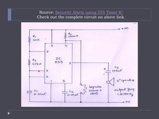
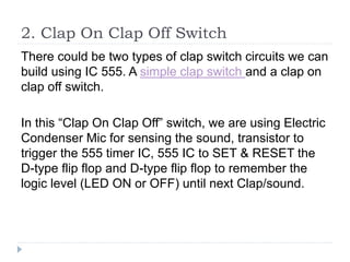
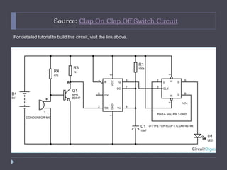
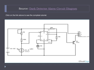
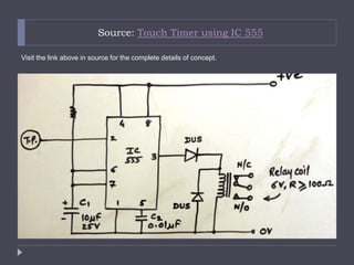
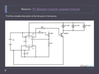
555 Timer Based Electronic Circuits
By: Jayant Bhatnagar
Introduction to 555 Timer IC
 555 timer IC is a chip used in a variety of applications
as a timer, pulse generator, and oscillator. It can be used
to provide time delays, as an oscillator, and also as a flip-
flop element.
 Works in three different operatign modes – monostable,
astable and bistable.
 It operates on between 5 volts to 18 volts power supply
voltage.
 Adjustable Duty Cycle.
 Sinking or sourcing 200 mA of load current.
 The output of a 555 timer can be used to drive transistor-
transistor logic (TTL) due to its high current output.
1. Easy to Construct Security Alarm
 Here is an easy to build security alarm using 555
timer IC.
 We know that when pin-4 is connected to positive
potential, the IC works in normal condition, but
whenever, the pin-4 is connected to ground, it
overrides all functions of the IC and the output of the
IC remains LOW. This facility is used in the following
circuit to design a simple security system.
Source: Security Alarm using 555 Timer IC
Check out the complete circuit on above link.
2. Clap On Clap Off Switch
There could be two types of clap switch circuits we can
build using IC 555. A simple clap switch and a clap on
clap off switch.
In this “Clap On Clap Off” switch, we are using Electric
Condenser Mic for sensing the sound, transistor to
trigger the 555 timer IC, 555 IC to SET & RESET the
D-type flip flop and D-type flip flop to remember the
logic level (LED ON or OFF) until next Clap/sound.
Source: Clap On Clap Off Switch Circuit
For detailed tutorial to build this circuit, visit the link above.
3. Dark Detector Alarm
 Dark detector is an interesting application that
makes the circuit On and Off with presence of light.
Whenever LDR connected with the circuit, detects
dark in surrounding, it switch on the lights.
 Here we have used a buzzer to start an alarm on
detection of dark.
Source: Dark Detector Alarm Circuit Diagram
Click on the link above to see the complete tutorial.
4. Touch Timer
 Touch timer is an interesting application of IC 555.
Here the trigger pin-2 of 555 IC is sensitive to human
touch. This property is used in the circuit.
 When power supply is connected, output of the 555
IC remains low and the relay remains deactivated.
The timing capacitor C1 remains discharged into pin-
7 of the IC, ready to receive the trigger
pulse. Remember that, this condition of the circuit is
also known as STABLE STATE of the circuit.

Source: Touch Timer using IC 555
Visit the link above in source for the complete details of concept.
5. TV Remote Control Jammer
 This circuit stops the working of TV remote control by
transmitting the IR rays.
 The communication established in this circuit is of
frequency 32.5 KHz. That means the IR LED blinks
at a rate of 32 KHz. Because this is too fast for a
camera to pick, It picks up continuous turned on
pulse.
Source: TV Remote Control Jammer Circuit
Find the complete description at the link given in the source.
 For more 555 based circuits and applications, here
are some great sources to learn the working and
design some interesting applications using different
operating modes of 555 IC:
 https://en.wikipedia.org/wiki/555_timer_IC
 http://www.yashplus.com/category/practical-
applications-of-ic-555/
 http://circuitdigest.com/555-timer-circuits
 http://makezine.com/2012/08/24/555-timer-weekend-
projects/

555 timer based electronic circuits

  • 1.
    555 Timer BasedElectronic Circuits By: Jayant Bhatnagar
  • 2.
    Introduction to 555Timer IC  555 timer IC is a chip used in a variety of applications as a timer, pulse generator, and oscillator. It can be used to provide time delays, as an oscillator, and also as a flip- flop element.  Works in three different operatign modes – monostable, astable and bistable.  It operates on between 5 volts to 18 volts power supply voltage.  Adjustable Duty Cycle.  Sinking or sourcing 200 mA of load current.  The output of a 555 timer can be used to drive transistor- transistor logic (TTL) due to its high current output.
  • 3.
    1. Easy toConstruct Security Alarm  Here is an easy to build security alarm using 555 timer IC.  We know that when pin-4 is connected to positive potential, the IC works in normal condition, but whenever, the pin-4 is connected to ground, it overrides all functions of the IC and the output of the IC remains LOW. This facility is used in the following circuit to design a simple security system.
  • 4.
    Source: Security Alarmusing 555 Timer IC Check out the complete circuit on above link.
  • 5.
    2. Clap OnClap Off Switch There could be two types of clap switch circuits we can build using IC 555. A simple clap switch and a clap on clap off switch. In this “Clap On Clap Off” switch, we are using Electric Condenser Mic for sensing the sound, transistor to trigger the 555 timer IC, 555 IC to SET & RESET the D-type flip flop and D-type flip flop to remember the logic level (LED ON or OFF) until next Clap/sound.
  • 6.
    Source: Clap OnClap Off Switch Circuit For detailed tutorial to build this circuit, visit the link above.
  • 7.
    3. Dark DetectorAlarm  Dark detector is an interesting application that makes the circuit On and Off with presence of light. Whenever LDR connected with the circuit, detects dark in surrounding, it switch on the lights.  Here we have used a buzzer to start an alarm on detection of dark.
  • 8.
    Source: Dark DetectorAlarm Circuit Diagram Click on the link above to see the complete tutorial.
  • 9.
    4. Touch Timer Touch timer is an interesting application of IC 555. Here the trigger pin-2 of 555 IC is sensitive to human touch. This property is used in the circuit.  When power supply is connected, output of the 555 IC remains low and the relay remains deactivated. The timing capacitor C1 remains discharged into pin- 7 of the IC, ready to receive the trigger pulse. Remember that, this condition of the circuit is also known as STABLE STATE of the circuit. 
  • 10.
    Source: Touch Timerusing IC 555 Visit the link above in source for the complete details of concept.
  • 11.
    5. TV RemoteControl Jammer  This circuit stops the working of TV remote control by transmitting the IR rays.  The communication established in this circuit is of frequency 32.5 KHz. That means the IR LED blinks at a rate of 32 KHz. Because this is too fast for a camera to pick, It picks up continuous turned on pulse.
  • 12.
    Source: TV RemoteControl Jammer Circuit Find the complete description at the link given in the source.
  • 13.
     For more555 based circuits and applications, here are some great sources to learn the working and design some interesting applications using different operating modes of 555 IC:  https://en.wikipedia.org/wiki/555_timer_IC  http://www.yashplus.com/category/practical- applications-of-ic-555/  http://circuitdigest.com/555-timer-circuits  http://makezine.com/2012/08/24/555-timer-weekend- projects/