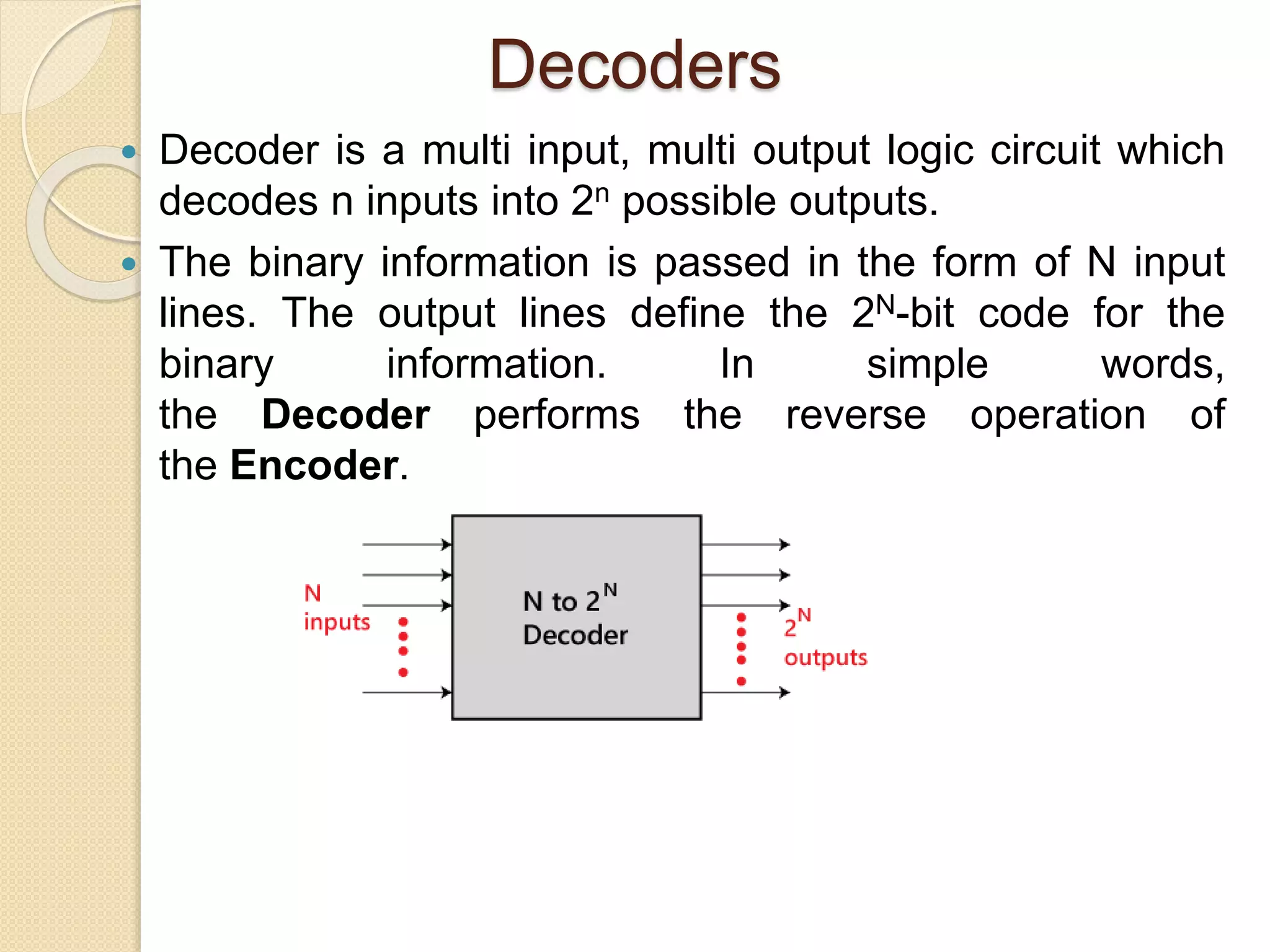
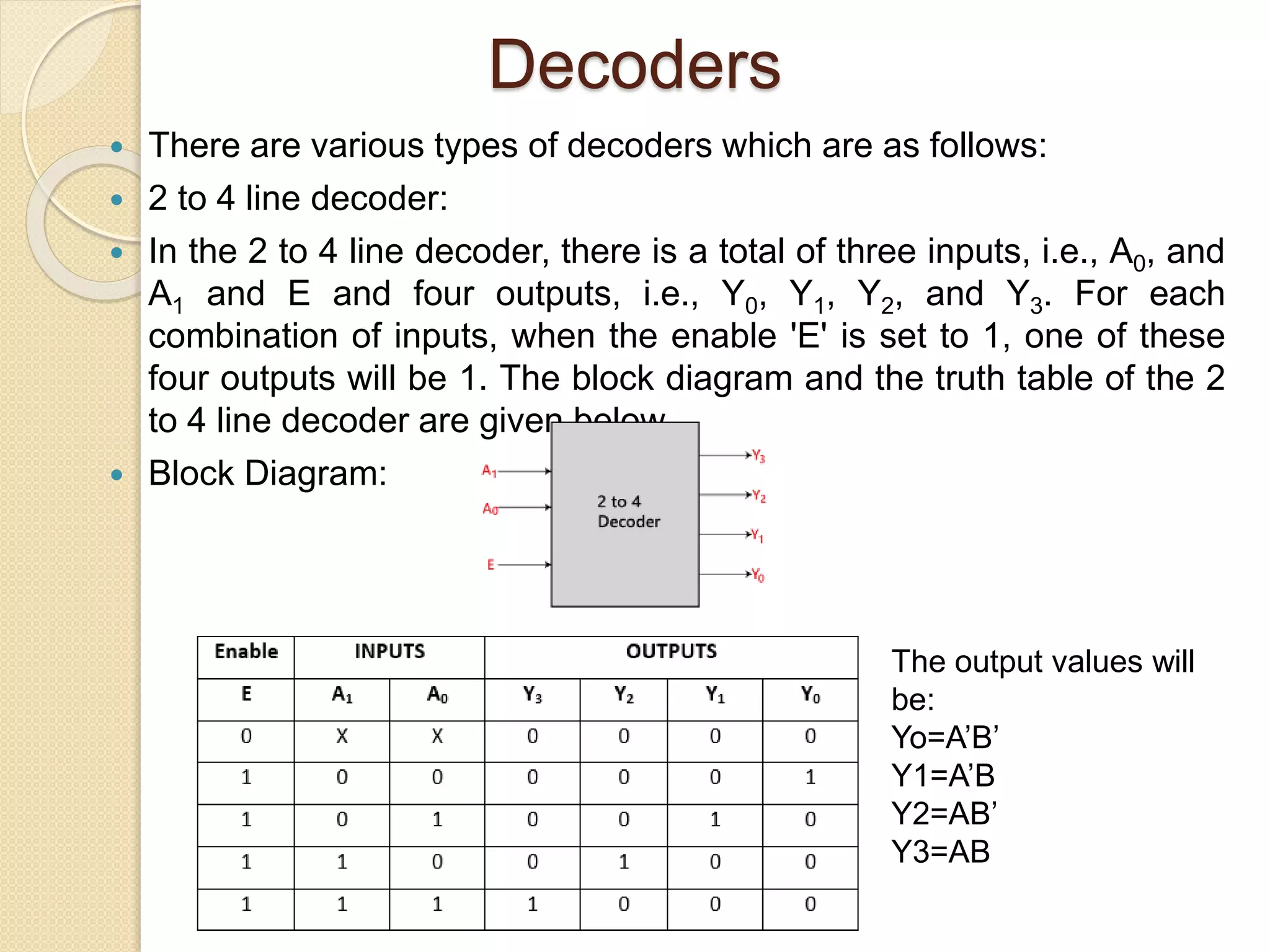
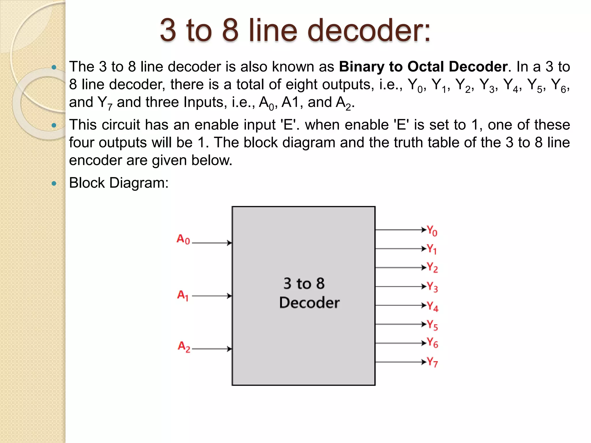
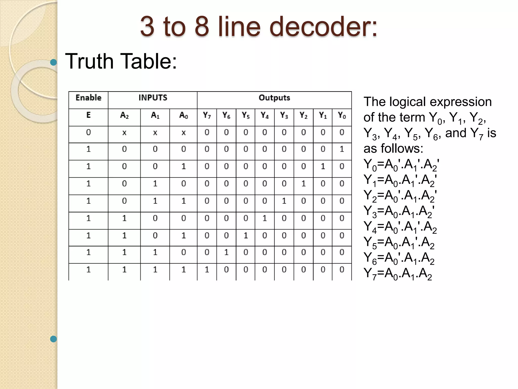
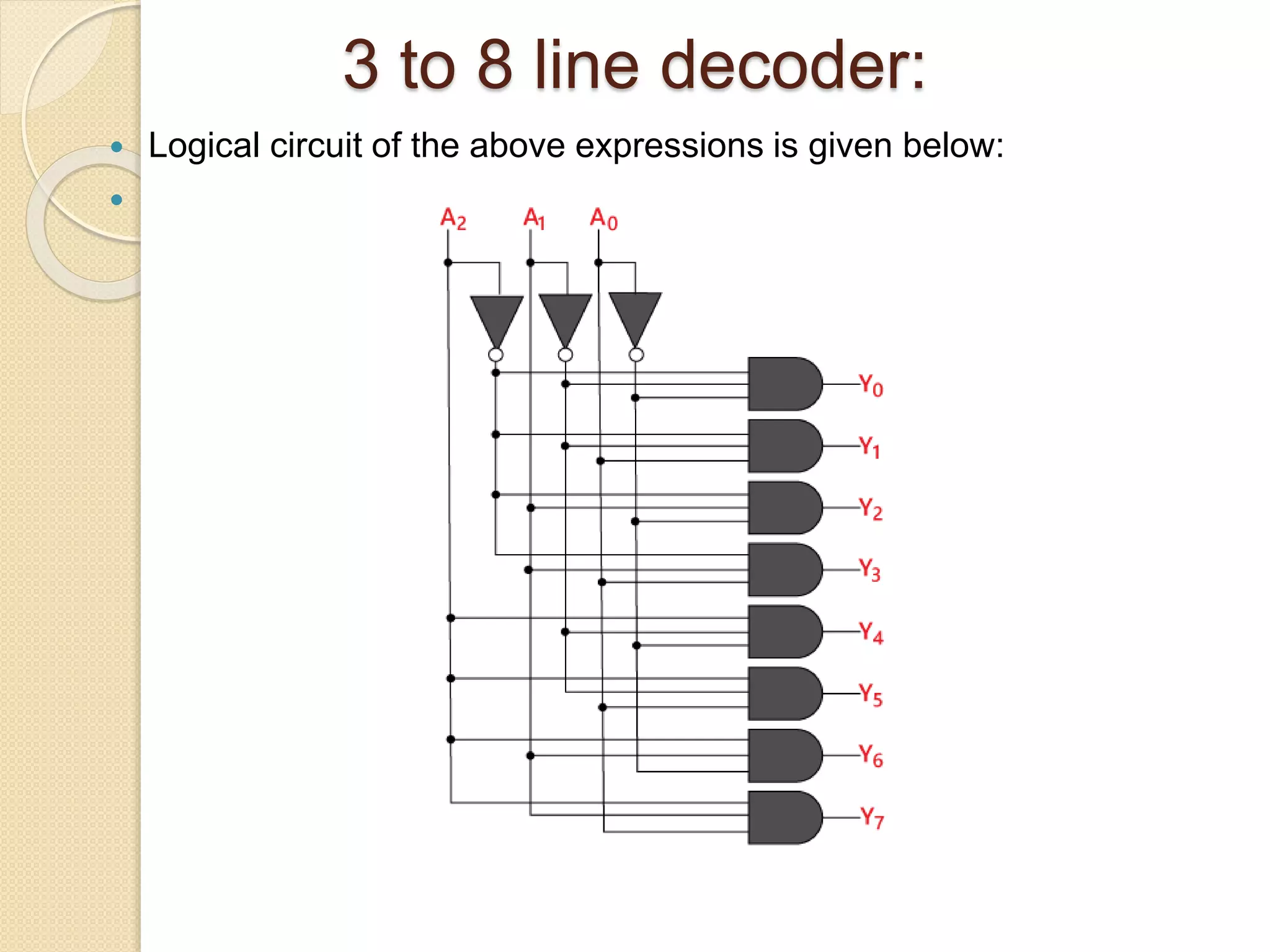
Decoders
Prof. Neeraj Bhargava
Mrs. Pooja Dixit
Department of Computer Science, School of
Engineering & System Sciences
MDS University Ajmer, Rajasthan
Decoders
 Decoder is a multi input, multi output logic circuit which
decodes n inputs into 2n possible outputs.
 The binary information is passed in the form of N input
lines. The output lines define the 2N-bit code for the
binary information. In simple words,
the Decoder performs the reverse operation of
the Encoder.
Decoders
 There are various types of decoders which are as follows:
 2 to 4 line decoder:
 In the 2 to 4 line decoder, there is a total of three inputs, i.e., A0, and
A1 and E and four outputs, i.e., Y0, Y1, Y2, and Y3. For each
combination of inputs, when the enable 'E' is set to 1, one of these
four outputs will be 1. The block diagram and the truth table of the 2
to 4 line decoder are given below.
 Block Diagram:
The output values will
be:
Yo=A’B’
Y1=A’B
Y2=AB’
Y3=AB
Decoders
 The binary inputs A and B determine which output line from Q0 to Q3
is “HIGH” at logic level “1” while the remaining outputs are held
“LOW” at logic “0” so only one output can be active (HIGH) at any
one time. Therefore, whichever output line is “HIGH” identifies the
binary code present at the input, in other words, it “decodes” the
binary input.
 Some binary decoders have an additional input pin labeled “Enable”
that controls the outputs from the device. This extra input allows the
outputs of the decoder to be turned “ON” or “OFF” as required. The
output is only generated when the Enable input has value 1;
otherwise, all outputs are 0. Only a small change in the
implementation is required: the Enable input is fed into the AND
gates which produce the outputs.
Decoders
 Logical circuit of the above expressions is
given below:

3 to 8 line decoder:
 The 3 to 8 line decoder is also known as Binary to Octal Decoder. In a 3 to
8 line decoder, there is a total of eight outputs, i.e., Y0, Y1, Y2, Y3, Y4, Y5, Y6,
and Y7 and three Inputs, i.e., A0, A1, and A2.
 This circuit has an enable input 'E'. when enable 'E' is set to 1, one of these
four outputs will be 1. The block diagram and the truth table of the 3 to 8 line
encoder are given below.
 Block Diagram:
3 to 8 line decoder:
 Truth Table:

The logical expression
of the term Y0, Y1, Y2,
Y3, Y4, Y5, Y6, and Y7 is
as follows:
Y0=A0'.A1'.A2'
Y1=A0.A1'.A2'
Y2=A0'.A1.A2'
Y3=A0.A1.A2'
Y4=A0'.A1'.A2
Y5=A0.A1'.A2
Y6=A0'.A1.A2
Y7=A0.A1.A2
3 to 8 line decoder:
 Logical circuit of the above expressions is given below:

Assignment Questions
 Q1. construct a 3 X 8 decoder using two 2 X
4 decoder with one enable.
 Q3. construct a 4 X 16 decoder using two 3
X 8 decoder with one enable.
Decoders

Decoders

  • 1.
    Decoders Prof. Neeraj Bhargava Mrs.Pooja Dixit Department of Computer Science, School of Engineering & System Sciences MDS University Ajmer, Rajasthan
  • 2.
    Decoders  Decoder isa multi input, multi output logic circuit which decodes n inputs into 2n possible outputs.  The binary information is passed in the form of N input lines. The output lines define the 2N-bit code for the binary information. In simple words, the Decoder performs the reverse operation of the Encoder.
  • 3.
    Decoders  There arevarious types of decoders which are as follows:  2 to 4 line decoder:  In the 2 to 4 line decoder, there is a total of three inputs, i.e., A0, and A1 and E and four outputs, i.e., Y0, Y1, Y2, and Y3. For each combination of inputs, when the enable 'E' is set to 1, one of these four outputs will be 1. The block diagram and the truth table of the 2 to 4 line decoder are given below.  Block Diagram: The output values will be: Yo=A’B’ Y1=A’B Y2=AB’ Y3=AB
  • 4.
    Decoders  The binaryinputs A and B determine which output line from Q0 to Q3 is “HIGH” at logic level “1” while the remaining outputs are held “LOW” at logic “0” so only one output can be active (HIGH) at any one time. Therefore, whichever output line is “HIGH” identifies the binary code present at the input, in other words, it “decodes” the binary input.  Some binary decoders have an additional input pin labeled “Enable” that controls the outputs from the device. This extra input allows the outputs of the decoder to be turned “ON” or “OFF” as required. The output is only generated when the Enable input has value 1; otherwise, all outputs are 0. Only a small change in the implementation is required: the Enable input is fed into the AND gates which produce the outputs.
  • 5.
    Decoders  Logical circuitof the above expressions is given below: 
  • 6.
    3 to 8line decoder:  The 3 to 8 line decoder is also known as Binary to Octal Decoder. In a 3 to 8 line decoder, there is a total of eight outputs, i.e., Y0, Y1, Y2, Y3, Y4, Y5, Y6, and Y7 and three Inputs, i.e., A0, A1, and A2.  This circuit has an enable input 'E'. when enable 'E' is set to 1, one of these four outputs will be 1. The block diagram and the truth table of the 3 to 8 line encoder are given below.  Block Diagram:
  • 7.
    3 to 8line decoder:  Truth Table:  The logical expression of the term Y0, Y1, Y2, Y3, Y4, Y5, Y6, and Y7 is as follows: Y0=A0'.A1'.A2' Y1=A0.A1'.A2' Y2=A0'.A1.A2' Y3=A0.A1.A2' Y4=A0'.A1'.A2 Y5=A0.A1'.A2 Y6=A0'.A1.A2 Y7=A0.A1.A2
  • 8.
    3 to 8line decoder:  Logical circuit of the above expressions is given below: 
  • 9.
    Assignment Questions  Q1.construct a 3 X 8 decoder using two 2 X 4 decoder with one enable.  Q3. construct a 4 X 16 decoder using two 3 X 8 decoder with one enable.