Download as PDF, PPTX
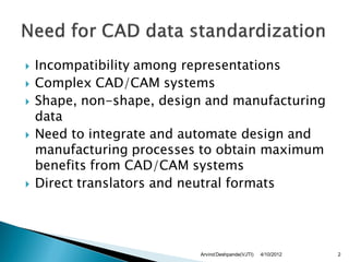
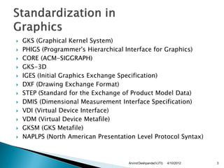
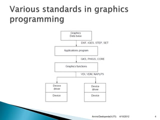
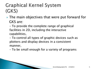
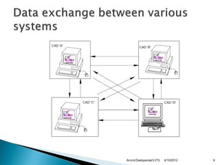
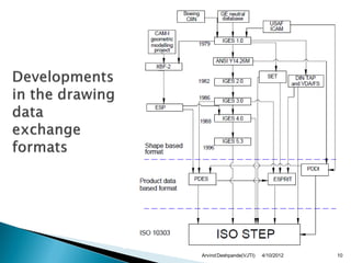
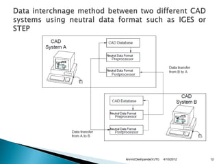
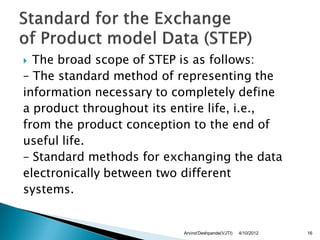

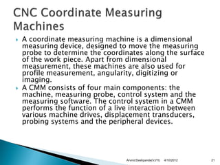
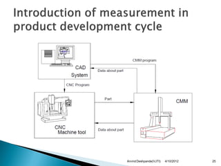

The document discusses various graphics standards and file formats used for CAD/CAM data exchange and integration. It describes early graphics standards like GKS and PHIGS. It then covers important file formats used for CAD data exchange like IGES, STEP, DXF, as well as formats for dimensional inspection data like DMIS. It provides details on the structure and capabilities of formats like IGES and STEP which aim to integrate design and manufacturing data across different CAD/CAM systems.


![Getting Started with Apache Spark: Big Data Made Simple [Free Meetup]](https://cdn.slidesharecdn.com/ss_thumbnails/apachesparkgettingstarted-260203175547-8361bcc3-thumbnail.jpg?width=640&height=640&fit=bounds)


