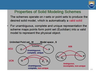
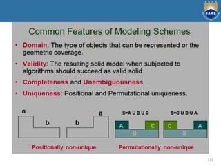
PPT
ADVANCED COMPUTER AIDED DESIGN
DEPARTMENT OF MECHANICAL ENGINEERING
M.TECH : CAD / CAM - I SEM
Dr. K RAGHU RAM MOHAN REDDY
by
UNIT-1: PRINCIPLES OF COMPUTER GRAPHICS
2
Introduction, graphic primitives, point plotting, lines,
Bresenham”s circle algorithm, ellipse, transformation in
graphics, coordinate systems, view port, 2D and 3D
transformation, hidden surface removal, reflection, shading
and generation of character.
Syllabus
3
Classification of computer graphics
4
Graphic Primitives
5
Display devices
Output devices include:
• CRT
• Random scan display
• Rastar scan display
• Monitors
• Speakers
• Headphones
• Printer
Cathode ray tube
6
Rastar Scan Display
7
8
Bresenham’s line algorithm
9
10
Two Dimensional Transformations
1. Introduction
2. What is transformation
3. Basic information
4. Translation
5. Rotation
6. Scaling
11
12
13
Scaling
14
Three Dimensional Transformations
1. Introduction
2. 3D transformation
3. Translation
4. Rotation
5. Scaling
15
16
Rotation
17
Hidden Surface Removal
The Depth Buffer Algorithm
Warnock’s Algorithm
18
19
20
21
22
23
24
Unit-II: CAD TOOLS
25
Syllabus
Definition of CAD Tools, Types of system, CAD/CAM system
evaluation criteria, brief treatment of input and output devices.
Graphics standard, functional areas of CAD, Modeling and
viewing, software documentation, efficient use of CAD software;
Geometric modeling: Types of mathematical representation of
curves, wire frame models wire frame entities parametric
representation of synthetic curves hermite cubic splines Bezier
curves Bezier splines rational curves.
26
27
28
29
30
31
32
33
34
35
36
37
38
39
40
41
42
43
44
45
46
47
48
49
Unit- III: SURFACE MODELING
50
Syllabus
Mathematical representation surfaces, surface model, surface
entities surface representation.
Parametric representation of surfaces, plane surface, rule
surface, surface of revolution, tabulated cylinder.
51
Basic modeling techniques are
1. Wire frame modeling
2. Surface modeling
3. Solid modeling
52
53
Wireframe modeling is the process of visual presentation of
a three-dimensional or physical object used in 3-D computer
graphics. It is an abstract edge or skeletal representation of a
real-world 3-D object using lines and curves.
Merits:
Simple to construct for 2D and simple and
symmetric 3D objects
Designer needs little training
System needs little memory
Take less manipulation time
Retrieving and editing can be done easy
Consumes less time
Best suitable for manipulations as orthographic
isometric and perspective views.
54
Surface modelling
Surface models define the surface features, as well as the edges,
of objects. Different types of spline curves are used to create
surface patches with different modelling characteristics.
Merits:
It is less ambiguous.
Complex surfaces can be easily identified.
It removes hidden line and adds realism.
Demerits:
Difficult to construct.
Difficult to calculate mass property.
More time is required for creation.
Requires high storage space as compared to wire frame
modelling.
Also requires more time for manipulation.
55
56
57
58
59
60
61
62
63
64
65
66
67
68
69
70
71
72
73
74
75
Unit- IV :PARAMETRIC REPRESENTATION OF
SYNTHETIC SURFACES
76
Parametric representation of synthetic surfaces: Hermite
Bicubic surface, Bezier surface, Bezier Spline surface, COONs
surface, Blending surface Sculptured surface, Surface
manipulation; Displaying, Segmentation, Trimming,
Intersection, Transformations (both 2D and 3D).
Syllabus
77
78
79
80
81
82
83
84
85
86
87
88
89
90
91
92
93
Unit – V : GEOMETRICMODELLING-3D
94
Syllabus
Geometricmodelling-3D: Solid modeling, solid representation,
boundary representation (B-rep), Constructive solid geometry
(CSG). CAD/CAM exchange: Evaluation of data, exchange format,
IGES data representations and structure, STEP Architecture,
implementation, ACIS and DXF; Design applications: Mechanical
tolerances, mass property calculations, finite element modeling
and analysis and mechanical assembly; Collaborative engineering:
Collaborative design, principles, approaches, tools, design systems.
95
96
Solid Modelling
Solid Modelling is a modelling that provides a complete representation
of an object than a wire frame modelling and surface modelling. In this
model, the appearance of an object is displayed in solid design.
Merits:
Complete modelling.
Unambiguous.
Best suitable for calculating mass properties.
Very much suitable for automated applications.
Fast creation.
Gives huge information.
Demerits:
Requires large memory.
Slow manipulation.
Some manipulations can be complex and require tedious procedure.
97
98
99
100
101
102
103
104
105
106
107
108
109
110
111
Data Exchange formats and standards
112
IGES specification defines the format of the file, language
format, and the product definition data in these formats. The
product definition includes geometric, topological, and non-
geometric data. The geometry part defines the geometric
entities to be used to define the geometry. The topology part
defines the entities to describe the relationships between the
geometric entities. The geometric shape of a product is
described using these two parts (i.e. geometry and topology).
The non-geometric part can be divided into annotation,
definition, and organization. The annotation category consists of
dimensions, drafting notations, text, etc. The definition category
allows users to define specific properties of individual or
collections of entities. The organization category defines
groupings of geometric, annotation, or property elements.
113
An IGES file consists of six sections: Flag, Start, Global, Directory
Entry, Parameter Data, and Terminate. Each entity instance consists
of a directory entry and parameter data entry. The directory entry
provides an index and includes attributes to describe the data. The
parameter data defines the specific entity. Parameter data are
defined by fixed length records, according to the corresponding
entity. Each entity instance has bi-directional pointers between the
directory entry and the parameter data section.
114
DXF (Data eXchange Format) was originally developed by
Autodesk, Inc., the vendor of AutoCAD. It has become a "de-
facto" standard among most CAD vendors and is in wide use to
exchange 2D/3D wireframe data. All implementations of
AutoCAD accept this format and are able to convert it to and
from their internal representation. A DXF file is a complete
representation of the AutoCAD drawing database thus some
features or concepts can't be used by other CAD systems. The
DXF version R13 supports wireframe, surface, and solid
representations.
115
A DXF file consists of four sections: Header, Table, Block, and
Entity section. The header section contains general information
about the drawing. Each parameter has a variable name and an
associated value. The table section contains definitions of line
types, layers, text styles, views, etc. The block section contains
entities for block definitions. These entities define the blocks
used in the drawing. The format of the entities in the block
section is identical to entities in the entity section. The entity
section contains the drawing entities, including any block
references. Items in the entity section exist also in the block
section and the appearance of entities in the two sections is
identical.
116
STEP (STandard for the Exchange of Product model data)
is a new International Standard (ISO 10303) for
representing and exchanging product model information.
It includes an object-flavored data specification language,
EXPRESS, to describe the representation of the data. STEP
defines also implementation methods, for instance, a
physical transfer file, and offers different resources, e.g.
geometric and topological representation.
117
The objective of STEP is to offer system-independent
mechanism to describe the product information in
computer aided systems throughout its lifetime. It
separates the representation of product information
from the implementation methods. Implementation
methods are used for data exchange. The
representation offers a definition of product
information to many applications. STEP provides also a
basis for archiving product information and a
methodology for the conformance testing of
implementations.
118
STEP does not only define the geometric shape of a product: it
also includes topology, features, tolerance specifications,
material properties, etc. necessary to completely define a
product for the purposes of design, analysis, manufacture, test,
inspection and product support. The use of STEP is still very
modest but it is growing all the time. The majority of CAD
system vendors has implemented or is implementing STEP pre-
and postprocessors for their CAD systems. STEP is an evolving
standard that will cover the whole product life cycle in terms of
data sharing, storage and exchange. It is the most important
and largest effort ever established in engineering domain and
will replace current CAD exchange standards.
Collaborative Engineering
119
Collaborative Engineering
120
Collaborative Engineering
121
Collaborative Engineering
122
Collaborative Engineering
123

A CAD ppt 25-10-19.pdf

  • 1.
    PPT ADVANCED COMPUTER AIDEDDESIGN DEPARTMENT OF MECHANICAL ENGINEERING M.TECH : CAD / CAM - I SEM Dr. K RAGHU RAM MOHAN REDDY by
  • 2.
    UNIT-1: PRINCIPLES OFCOMPUTER GRAPHICS 2 Introduction, graphic primitives, point plotting, lines, Bresenham”s circle algorithm, ellipse, transformation in graphics, coordinate systems, view port, 2D and 3D transformation, hidden surface removal, reflection, shading and generation of character. Syllabus
  • 3.
  • 4.
  • 5.
    Graphic Primitives 5 Display devices Outputdevices include: • CRT • Random scan display • Rastar scan display • Monitors • Speakers • Headphones • Printer
  • 6.
  • 7.
  • 8.
  • 9.
  • 10.
    10 Two Dimensional Transformations 1.Introduction 2. What is transformation 3. Basic information 4. Translation 5. Rotation 6. Scaling
  • 11.
  • 12.
  • 13.
  • 14.
    14 Three Dimensional Transformations 1.Introduction 2. 3D transformation 3. Translation 4. Rotation 5. Scaling
  • 15.
  • 16.
  • 17.
    17 Hidden Surface Removal TheDepth Buffer Algorithm Warnock’s Algorithm
  • 18.
  • 19.
  • 20.
  • 21.
  • 22.
  • 23.
  • 24.
  • 25.
    Unit-II: CAD TOOLS 25 Syllabus Definitionof CAD Tools, Types of system, CAD/CAM system evaluation criteria, brief treatment of input and output devices. Graphics standard, functional areas of CAD, Modeling and viewing, software documentation, efficient use of CAD software; Geometric modeling: Types of mathematical representation of curves, wire frame models wire frame entities parametric representation of synthetic curves hermite cubic splines Bezier curves Bezier splines rational curves.
  • 26.
  • 27.
  • 28.
  • 29.
  • 30.
  • 31.
  • 32.
  • 33.
  • 34.
  • 35.
  • 36.
  • 37.
  • 38.
  • 39.
  • 40.
  • 41.
  • 42.
  • 43.
  • 44.
  • 45.
  • 46.
  • 47.
  • 48.
  • 49.
  • 50.
    Unit- III: SURFACEMODELING 50 Syllabus Mathematical representation surfaces, surface model, surface entities surface representation. Parametric representation of surfaces, plane surface, rule surface, surface of revolution, tabulated cylinder.
  • 51.
    51 Basic modeling techniquesare 1. Wire frame modeling 2. Surface modeling 3. Solid modeling
  • 52.
  • 53.
    53 Wireframe modeling isthe process of visual presentation of a three-dimensional or physical object used in 3-D computer graphics. It is an abstract edge or skeletal representation of a real-world 3-D object using lines and curves. Merits: Simple to construct for 2D and simple and symmetric 3D objects Designer needs little training System needs little memory Take less manipulation time Retrieving and editing can be done easy Consumes less time Best suitable for manipulations as orthographic isometric and perspective views.
  • 54.
    54 Surface modelling Surface modelsdefine the surface features, as well as the edges, of objects. Different types of spline curves are used to create surface patches with different modelling characteristics. Merits: It is less ambiguous. Complex surfaces can be easily identified. It removes hidden line and adds realism. Demerits: Difficult to construct. Difficult to calculate mass property. More time is required for creation. Requires high storage space as compared to wire frame modelling. Also requires more time for manipulation.
  • 55.
  • 56.
  • 57.
  • 58.
  • 59.
  • 60.
  • 61.
  • 62.
  • 63.
  • 64.
  • 65.
  • 66.
  • 67.
  • 68.
  • 69.
  • 70.
  • 71.
  • 72.
  • 73.
  • 74.
  • 75.
  • 76.
    Unit- IV :PARAMETRICREPRESENTATION OF SYNTHETIC SURFACES 76 Parametric representation of synthetic surfaces: Hermite Bicubic surface, Bezier surface, Bezier Spline surface, COONs surface, Blending surface Sculptured surface, Surface manipulation; Displaying, Segmentation, Trimming, Intersection, Transformations (both 2D and 3D). Syllabus
  • 77.
  • 78.
  • 79.
  • 80.
  • 81.
  • 82.
  • 83.
  • 84.
  • 85.
  • 86.
  • 87.
  • 88.
  • 89.
  • 90.
  • 91.
  • 92.
  • 93.
  • 94.
    Unit – V: GEOMETRICMODELLING-3D 94 Syllabus Geometricmodelling-3D: Solid modeling, solid representation, boundary representation (B-rep), Constructive solid geometry (CSG). CAD/CAM exchange: Evaluation of data, exchange format, IGES data representations and structure, STEP Architecture, implementation, ACIS and DXF; Design applications: Mechanical tolerances, mass property calculations, finite element modeling and analysis and mechanical assembly; Collaborative engineering: Collaborative design, principles, approaches, tools, design systems.
  • 95.
  • 96.
    96 Solid Modelling Solid Modellingis a modelling that provides a complete representation of an object than a wire frame modelling and surface modelling. In this model, the appearance of an object is displayed in solid design. Merits: Complete modelling. Unambiguous. Best suitable for calculating mass properties. Very much suitable for automated applications. Fast creation. Gives huge information. Demerits: Requires large memory. Slow manipulation. Some manipulations can be complex and require tedious procedure.
  • 97.
  • 98.
  • 99.
  • 100.
  • 101.
  • 102.
  • 103.
  • 104.
  • 105.
  • 106.
  • 107.
  • 108.
  • 109.
  • 110.
  • 111.
  • 112.
    Data Exchange formatsand standards 112 IGES specification defines the format of the file, language format, and the product definition data in these formats. The product definition includes geometric, topological, and non- geometric data. The geometry part defines the geometric entities to be used to define the geometry. The topology part defines the entities to describe the relationships between the geometric entities. The geometric shape of a product is described using these two parts (i.e. geometry and topology). The non-geometric part can be divided into annotation, definition, and organization. The annotation category consists of dimensions, drafting notations, text, etc. The definition category allows users to define specific properties of individual or collections of entities. The organization category defines groupings of geometric, annotation, or property elements.
  • 113.
    113 An IGES fileconsists of six sections: Flag, Start, Global, Directory Entry, Parameter Data, and Terminate. Each entity instance consists of a directory entry and parameter data entry. The directory entry provides an index and includes attributes to describe the data. The parameter data defines the specific entity. Parameter data are defined by fixed length records, according to the corresponding entity. Each entity instance has bi-directional pointers between the directory entry and the parameter data section.
  • 114.
    114 DXF (Data eXchangeFormat) was originally developed by Autodesk, Inc., the vendor of AutoCAD. It has become a "de- facto" standard among most CAD vendors and is in wide use to exchange 2D/3D wireframe data. All implementations of AutoCAD accept this format and are able to convert it to and from their internal representation. A DXF file is a complete representation of the AutoCAD drawing database thus some features or concepts can't be used by other CAD systems. The DXF version R13 supports wireframe, surface, and solid representations.
  • 115.
    115 A DXF fileconsists of four sections: Header, Table, Block, and Entity section. The header section contains general information about the drawing. Each parameter has a variable name and an associated value. The table section contains definitions of line types, layers, text styles, views, etc. The block section contains entities for block definitions. These entities define the blocks used in the drawing. The format of the entities in the block section is identical to entities in the entity section. The entity section contains the drawing entities, including any block references. Items in the entity section exist also in the block section and the appearance of entities in the two sections is identical.
  • 116.
    116 STEP (STandard forthe Exchange of Product model data) is a new International Standard (ISO 10303) for representing and exchanging product model information. It includes an object-flavored data specification language, EXPRESS, to describe the representation of the data. STEP defines also implementation methods, for instance, a physical transfer file, and offers different resources, e.g. geometric and topological representation.
  • 117.
    117 The objective ofSTEP is to offer system-independent mechanism to describe the product information in computer aided systems throughout its lifetime. It separates the representation of product information from the implementation methods. Implementation methods are used for data exchange. The representation offers a definition of product information to many applications. STEP provides also a basis for archiving product information and a methodology for the conformance testing of implementations.
  • 118.
    118 STEP does notonly define the geometric shape of a product: it also includes topology, features, tolerance specifications, material properties, etc. necessary to completely define a product for the purposes of design, analysis, manufacture, test, inspection and product support. The use of STEP is still very modest but it is growing all the time. The majority of CAD system vendors has implemented or is implementing STEP pre- and postprocessors for their CAD systems. STEP is an evolving standard that will cover the whole product life cycle in terms of data sharing, storage and exchange. It is the most important and largest effort ever established in engineering domain and will replace current CAD exchange standards.
  • 119.
  • 120.
  • 121.
  • 122.
  • 123.