Metal Additive Manufacturing - Basics Zero to One - June 2018bMatthew Burris
A brief on metal additive manufacturing. Covering the hype, realities, industry growth, where companies have found value with metal additive manufacturing, the value levers of metal additive manufacturing with case studies, and considerations of adopting metal additive manufacturing.
Additive Manufacturing: 3D Printing--Past, Present, and Future360mnbsu
This presentation explored the foundation of ‘the next industrial revolution’ - how additive manufacturing systems such as 3D printers and 3D production systems are changing the future of product development and manufacturing. Mr. Fischer presented examples of how design engineers use 3D production systems for concept modeling and prototyping, but also how manufacturing engineers are now employing these technologies for various applications such as jigs, fixtures, check gauges, and even as a bridge-to-tooling and low-volume end-use parts.
From the 2013 Taking Shape Summit: Additive Manufacturing: 3D Printing--Beyond Rapid Prototyping.
This was a presentation for the participants for the Core Relief workshop, October 3, on the island of Lesvos, Greece. It is intended as an introduction to the state of the art in 3d printing for a general public of professionals in the field of Humanitarian Aid. It contains tips, tricks and a lot of examples.
These slides use concepts from my (Jeff Funk) course entitled analyzing hi-tech opportunities to show how the cost and performance of additive manufacturing/3D printing is experiencing rapid improvements and thus it is becoming economically feasible for many new applications. All 3D printers have benefited from improvement sin microprocessors and sensors, which have enabled better process control. One new and one existing technique and the impact of improvements in electronic components on the performance and cost of additive manufacturing are discussed. First, continuous liquid interface production is a new technique that utilizes a unique design of digital light processing, a deadzone, and an oxygen permeable window. Improvements in the resolution of DLP, a form of MEMS, are occurring as smaller feature sizes are achieved, in the same way that increases in the number of transistors are achieved as transistor gate lengths are reduced. Second, an existing approach, Selective laser sintering, experiences improvements as higher powered lasers emerge. This technique melts metal powder and wires with an Ytterbium fiber laser whose power capabilities continue to be improved. This technique has already enabled GE to reduce the number of parts for an engine nozzle from 18 to 1, the weight by 25%, and the costs by a similar amount. The number of applications for SLA is expected to grow as the technique is improved through the use of higher powered lasers.
Is Additive Metal Manufacturing the Next Technological Wonder Drug? An article in Canadian Metalworking Magazine reviewing AMM's success with their two (2) EOS Model M290 e-Manufacturing DMLS Systems.
Additive manufacturing (AM) or 3D printing is maturing rapidly as a viable solution of make optimized parts for “real engineering” applications. The freedom of design that is achievable using AM process is un parallel in terms of reducing structural weight, reducing material cost, generating complex shapes and connections and introducing directional properties in a component. However, understanding of AM process and utilizing process parameters to optimize a design comes with many challenges. Currently, one of the emphasize is to use physics based realistic simulation to replicate the AM process numerically and relate process parameters to the concept of functional generative design that relates design with manufacturing process.
Current work, through a typical build example, discusses an integrated numerical solution on a digital platform that involves the following.
Generative Design involving topology optimization that creates parts in context of the manufacturing process and automatically generate variants of conceptual and detailed organic shapes that helps make informed business decisions based on physics-based analytic tools. Process planning that defines and customizes manufacturing environment including nesting parts automatically on the build tray, designing and generating optimal support structures, and creating machine specific slicing and scan path which is ready for print. Process simulation that automatically includes machine inputs for energy, material and supports into the simulation at layer, part and build levels for any additive manufacturing process and accurately predicts part distortions, residual stresses and as-built material behavior. Finally, the platform involves post processing to perform shape optimization where simulation is used to guide support-structure strategy for enhanced build yield, compensate distortion effects without the need to redesign the product tooling, produce high-quality morphed surface geometry with unchanged topology, and perform final in-service performance validations of manufactured part.
Study on the Fused Deposition Modelling In Additive ManufacturingIJERD Editor
Additive manufacturing process, also popularly known as 3-D printing, is a process where a product
is created in a succession of layers. It is based on a novel materials incremental manufacturing philosophy.
Unlike conventional manufacturing processes where material is removed from a given work price to derive the
final shape of a product, 3-D printing develops the product from scratch thus obviating the necessity to cut away
materials. This prevents wastage of raw materials. Commonly used raw materials for the process are ABS
plastic, PLA and nylon. Recently the use of gold, bronze and wood has also been implemented. The complexity
factor of this process is 0% as in any object of any shape and size can be manufactured.
When Additive Manufacturing and 3D Printing Makes Sense and When It Doesn’t360mnbsu
This presentation gave an overview of technologies currently available and their use in industry, while highlighting the differences between 3D Printing & Additive Manufacturing.
From the 2013 Taking Shape Summit: Additive Manufacturing: 3D Printing--Beyond Rapid Prototyping.
Both traditional and modern manufacturing methods have changed the face of the manufacturing industry over the years. But which method is best for the job at hand? Here's an overview of how the most common manufacturing methods compare.
The impact of additive manufacturing on micro reactor technology (slideshare ...Raf Reintjens
The continuous tubular reactor is a well-known concept which is applied broadly and has proven its value to the chemical industry. In essence the micro reactor is nothing else than a tubular reactor with an unusual small diameter. Its excellent performance originates from the fact that the characteristic time for heat and mass transfer scales quadratic with the length scale. Ten times smaller diameter results in a hundred times faster transfer.
But, the very principles that lead to high performance seem to disable economical viable applications. Even at ‘micro reactor level’ productivity an astronomically large number of parallel channels is required to reach plant scale production capacities. The negative influence on manufacturability and cost can be countered by influencing the fluid dynamics inside the channel. Making use of secondary flow phenomena we succeed to maintain the ‘micro reactor level’ productivity at mm sized channel diameters. The desired secondary flow effect originates from influencing the shape, geometry and lay-out of the channel.
Selective laser melting (3D metal printing) is a new fast developing manufacturing technology that delivers excellent freedom of design combined with a promising cost level. Those properties match very well with the needs within micro reactor technology, and act as a strong enabler for applications in process development as well as industrial production.
Understand the important aspects of digital design and digital manufacturing, what technologies are available, and how to embed rapid prototyping technologies to fast track your development program.
3D printing market - a global study (2014-2022)BIS Research
The report presents a detailed market analysis of 3D printing and Additive Manufacturing by incorporating complete pricing and cost analysis of 3D printers and materials. Besides porter’s and PESTLE analysis of the market have also been done. The report deals with all the driving factors, restraints, and opportunities with respect to the 3D printing and Additive Manufacturing market, which are helpful in identifying trends and key success factors for the industry.
Lastly, the current market landscape is covered with detailed competitive landscape and company profiles of all key players across the ecosystem. The report also formulates the entire value chain of the market, along with industry trends of 3D printing application industries and materials used with emphasis on market timelines & technology road-maps
computer-aided design and computer-aided manufacturing) refers to computer software that is used to both design and manufacture products. ... CAD/CAM applications are used to both design a product and program manufacturing processes, specifically, CNC machining.
Fundamentals of CAD/ CAM, Application of computers for Design and Manufacturing, Benefits of CAD/ CAM - Computer peripherals for CAD/ CAM, Design workstation, Graphic terminal, CAD/ CAM software- definition of system software and application software, CAD/ CAM database and structure. Geometric Modeling
Fundamentals of CAD/ CAM, Application of computers for Design and Manufacturing, Benefits of CAD/ CAM - Computer peripherals for CAD/ CAM, Design workstation, Graphic terminal, CAD/ CAM software- definition of system software and application software, CAD/ CAM database and structure
Unit 1 INTRODUCTION (COMPUTER AIDED DESIGN AND MANUFACTURING )ravis205084
UNIT I INTRODUCTION 9
Product cycle- Design process- sequential and concurrent engineering- Computer aided design –
CAD system architecture- Computer graphics – co-ordinate systems- 2D and 3D transformationshomogeneous
coordinates
- Line drawing -Clipping- viewing transformation-Brief introduction to CAD
and CAM – Manufacturing Planning, Manufacturing control- Introduction to CAD/CAM –CAD/CAM
concepts ––Types of production - Manufacturing models and Metrics – Mathematical models of
Production Performance
Computer application in different sectors of textile technology
Research and development of materials and textile process
Computer-aided textile production and process control
Production planning
Process control
Quality control
Inventory control
Analysis of engineering data
Solution of engineering problems
Textile machine manufacturing
Automation of textile machines, equipment's and processes
Scope of Computer Based Technology for Textile Application:
Generally, there are three terms that are frequently used:
CAD (Computer-Aided Design)
CAM (Computer-Aided Manufacturing)
CIM (Computer Integrated Manufacturing)
Somemore is there like,
4.CAT (Computer-Aided Testing)
5.CAE (Computer-Aided Engineering
Transforming Brand Perception and Boosting Profitabilityaaryangarg12
In today's digital era, the dynamics of brand perception, consumer behavior, and profitability have been profoundly reshaped by the synergy of branding, social media, and website design. This research paper investigates the transformative power of these elements in influencing how individuals perceive brands and products and how this transformation can be harnessed to drive sales and profitability for businesses.
Through an exploration of brand psychology and consumer behavior, this study sheds light on the intricate ways in which effective branding strategies, strategic social media engagement, and user-centric website design contribute to altering consumers' perceptions. We delve into the principles that underlie successful brand transformations, examining how visual identity, messaging, and storytelling can captivate and resonate with target audiences.
Methodologically, this research employs a comprehensive approach, combining qualitative and quantitative analyses. Real-world case studies illustrate the impact of branding, social media campaigns, and website redesigns on consumer perception, sales figures, and profitability. We assess the various metrics, including brand awareness, customer engagement, conversion rates, and revenue growth, to measure the effectiveness of these strategies.
The results underscore the pivotal role of cohesive branding, social media influence, and website usability in shaping positive brand perceptions, influencing consumer decisions, and ultimately bolstering sales and profitability. This paper provides actionable insights and strategic recommendations for businesses seeking to leverage branding, social media, and website design as potent tools to enhance their market position and financial success.
Dive into the innovative world of smart garages with our insightful presentation, "Exploring the Future of Smart Garages." This comprehensive guide covers the latest advancements in garage technology, including automated systems, smart security features, energy efficiency solutions, and seamless integration with smart home ecosystems. Learn how these technologies are transforming traditional garages into high-tech, efficient spaces that enhance convenience, safety, and sustainability.
Ideal for homeowners, tech enthusiasts, and industry professionals, this presentation provides valuable insights into the trends, benefits, and future developments in smart garage technology. Stay ahead of the curve with our expert analysis and practical tips on implementing smart garage solutions.
7 Alternatives to Bullet Points in PowerPointAlvis Oh
So you tried all the ways to beautify your bullet points on your pitch deck but it just got way uglier. These points are supposed to be memorable and leave a lasting impression on your audience. With these tips, you'll no longer have to spend so much time thinking how you should present your pointers.
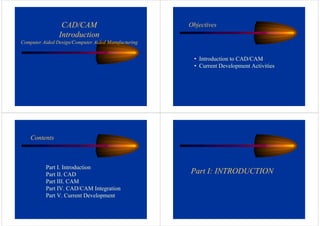
1. CAD/CAM
Introduction
Computer Aided Design/Computer Aided Manufacturing
Objectives
• Introduction to CAD/CAM
• Current Development Activities
Contents
Part I. Introduction
Part II. CAD
Part III. CAM
Part IV. CAD/CAM Integration
Part V. Current Development
Part I: INTRODUCTION
2. What is CAD/CAM (or CIM) Technology?
• CAD: makes representation of products and
perform analysis of the design
• CAM: prepare manufacturing processes and
drive machine tools
• CIM: CAD/CAM + Other Activities Such
As Operations Management and Master
Storage and Handling.
History of CAD/CAM/CIM
Operational Flow of CIM The classification of the manufacturing system of a company should
identify the activities in the three major process segments (ie, design,
manufacturing control and planning, and production) in CIM wheel.
Business
segment
Process
segment
Infrastructure &
resources
Manufacturing System Classification
3. Design Considerations
• Part must function correctly and last
reasonable duration of time
• Functional considerations involve weight,
strength, thermal properties, kinematics,
and dynamics, etc.
• Performance evaluation against design
specifications
This is determined by a part’s
• geometry
• material properties
• environment
• Part must be designed as closely as
possible to the design specifications
The economic factors include
• materials
• processing costs
• marketing details
Part II: CAD
CAD Technologies
Evolution
1950s: SAGE System (Analyze Radar Image with Light-pen)
1962: SketchPad at MIT (Interactive Graphics with SketchPad)
1960s: Digital Equipment Corporation, Control Data, IBM,
Univac, Applicon, Calma, ComputerVision, Intergraph (Calma
Graphics System, ComputerVision, CADD System, IBM
CADAM, CATIA, Intergraph Graphics System)
1970s: Recognized as Indispensible Tools to Improve
Productivities especially in ME, EE, and CE
1980s - 1990s: Widely Spread Due To Lower Price and availability
of PC
1990s - : Network Based such as Internet, LAN, and WAN
2000s- : Cloud Computing
CAD Structure
• Input Device
• Output Device
• CPU
• Memory
• Storage Device
• Communication Device
4. Haptic I/O
Data Glove
CAD Technological Issues
from Hardware Perspective
Graphics Terminal Performance
(Display Technology)
Computer Performance
Utilization of Existing
Leading-Edge Technologies
like Artificial Intelligence
(Pattern Recognition, Planning, Voice
Recognition, Robot Control, Fault Diagnosis,
and Expert Systems)
Electronic Image -> Visual Image
(CRT, LCD, LED with vector/raster painting)
Storage of Display Image Format
(Point-, Vector-, Relationship-Oriented Storage)
Production of Display Image from
Design
Execution of Mathematical Functions Needed
to Translate Stored Images into Display and to
Manipulate Vector Representation Designs in
Storage. Some Efforts are:
• Math-Coprocessor in PCs
• Pre-Fetch Methods to reduce I-time in Intel 8086-
Family of Processors
• RISC (Reduced Instruction Set Computer) to
reduce I-time
• Parallel Processors
• Super Computers
CAD Technological Issues
from Software Perspective
Geometric Modeling
Parametric and
Variational Design
Integrated Data Base
Management and Optimization
• Multi-View 2D Modeler
• 3D Wire Frame Modeler
• 3D Surface Modeler
• Solid Modeler -> CAM
• Stress Analysis
• CFD
• Kinematics Analysis for Moving Parts
• Simple Analysis like Area/Volume, Mass Calculations
• Artificial Intelligence (AI) which works with facts and rules
from which they can make deductions: Pattern Recognition,
Planning, Voice Recognition, Robot Control, Fault Diagnosis,
and Expert Systems.
* Virtual Reality (VR) Technology
• Scaling
• Rotation
• Translation
• Reflection
• Visualization
• Editing
• Dimensioning and Labeling
• Shading
• Real-Time Animation
Rendering
Analysis: Help Engineers to
Determine Feasibility of Design: FEM
and other computational methods
• CAD Drawing
• Engineering Analysis
• Modeling
• NC
• Robots
• Process Planning
• Management
• IGES
• …..
Feature-Based Design
CAD Data Exchangeability
• Since the IGES was first developed under the guidance of National Bureau of Standards (NBS)
in 1979, CAD/CAM data exchange had leaped beyond IGES. This brought about an effort from
the international community to introduce a single international standard for graphics data
exchange. As a result the Standard for the Exchange of Product Data Models (STEP, officially
the ISO standard 10303) was introduced. The STEP is a series of International Standards with
the goal of defining data across the full engineering and manufacturing life cycle to produce a
single international standard for product data exchange. There are currently several standards
like U.S.’ IGES, France’s SET, and Germany’s VDA-FS.
• The International Organization for Standardization (ISO) is a worldwide federation of national
standards bodies from some 100 countries, one from each country and established in 1947. In
USA an organization called The National Institute of Standards and Technology (NIST),
formerly the National Bureau of Standards, was established by Congress in 1901 to support
industry, commerce, scientific institutions, and all branches of Government. For nearly 100
years the NIST/NBS laboratories have worked with industry and government to advance
measurement science and develop standards.
• There is another collaborative effort under the project INDEX (Intelligent Data Extraction) at
Manchester Visualization Center of University of Manchester. This is also concerned with
exchangeability of CAD/CAM data among different systems that provides a flexible software
tool set.
6. Analyses
• Structural Analyses
• Heat Transfer Analyses
• Fluid Analyses
• Coupled-Field Analyses
• Linear and Nonlinear
Analyses
Choosing a Solid Modeler for
CAD/CAM Integration
• Flexibility (must be able to handle all kinds of objects)
• Robustness (should produce a consistent and proper solid)
• Simplicity (must be simple and user friendly)
• Performance (speed is important that should be improved with software
methodology and hardware)
• Economy (solid modeler is expensive, but will pay for itself as time goes on with
CAD/CAM)
Part III: CAM
The figure above shows some geometries to consider for tool-path generation.
There are various approaches to determine the tool path. For example, the
surface normal and tangent vectors at each point.
Tool Path Geometry
7. Milling Machines CAM Technologies
History
• 1909: Automation by Ford Automobile Company (Mass Production)
• 1923: Automatic Transfer Machines at Morris Engine Factory, England
• 1952: Numerical Controls (NC) for tool positioning thru computer commands
• 1959: Control Digital Computer at Texaco refinery, Texas
• 1960: Robot Implementation - Unimate based on NC principles
• 1965: Production-Line Computer Control (IBM developed plcc for circuit boards)
• 1970: Direct Numerical Control (DNC) --> Multiple-Machine Computer Control
(Japanese National Railways: several machine tools under simultaneous control of a computer)
• 1970-1972: Computer Numerical Control (CNC): each machine tool has its own memory (PC)
• 1975-1980: Distributed Numerical Control (DNC): a main computer downloads NC programs to
applicable machine. This is the key concept to CAM advances.
• 1980s: Cellular Manufacturing: A reduction of combinations in job shop control is achieved by identifying
families of parts that can be produced on a subset of equipment in the job shop. This determination of
families and equipment is most often done by group technology. Then the cell control computer download
NC programs and effect material handling between machines, frequently thru robot transfers.
• - : Flexible Manufacturing Systems: The idea of using a set of machines to produce a relatively
wide variety of products, with automatic movement of products through any sequence of machines, including
testing, is the heart of the flexible manufacturing systems.
•2000s: 3D Printing
Computers in Manufacturing
Manufacturing Control
Computer Control
(late 1950s)
Numerical Controls (NC)
Numerical control (NC) is a concept of machine control that consists of several steps such
as development of manufacturing plan for a part, programming numerical control
instructions, process the program to locate the tool path, and post-process for a specific
machine tool. NC activities consist of NC machines like CNC and DNC and processor
language like APT in addition to the human operator.
Robots in Manufacturing
Industrial robots have been used in the manufacturing
more than two decades. It is no doubt that robots will
play a crucial role in the future manufacturing.
Though, there are still quite challenging technologies
to overcome in this field of technology such as:
• vision system
• position sensing
• hand tactile sensing
• dexterous linkage
• control methodology.
8. Sensing/Measuring/Quality Controls
Sensing and measuring are also essential part of
manufacturing such as quality controls and had been
integrated into CAD/CAM.
CAM Technological Issues
from Software Perspective
Concurrent Engineering
Manufacturing Planning
and Control
Robotics
• Axiomatic Design
• DFM
• Design Science
• DFA
• Taguchi Method
• MPDR, Group Technology
• FMEA
• Production Control
• Cellular Manufacturing
• JIT Manufacturing
Measurement and Verification
• Hierarchical Code
• Attribute Code
• Process Planning (CAPP)
• Manual Approach
• Variant Approach
• Generative Approach
Group Technology
Computer Control and PLC
• Sensing
• Measuring
• Quality Control
• Timing
• Priority Interrupts
• Real-Time, Multi-Tasking Operating Systems
• Numerical Control (NC)
• NC/CNC/DNC Machines
• NC Programming – APT,ADAPT,EXAPT,etc.
Artificial
Intelligence
Part IV: CAD/CAM Integration
Concurrent Engineering
CE is an approach to design
and manufacturing activities,
which tries to complete the
design in parallel to process
planning, field-support,
quality control, and other
manufacturing-related
activities. Its mission is to
design and optimize the
product under the constraints
such as functionality,
producibility, and cost.
• Axiomatic design
• Design for manufacturing (DFM)
• Design science
• Design for assembly (DFA)
• Taguchi method for robust design
• Manufacturing planning and control
• Computer Aided Process Planning (CAPP)
• Computer-aided DFM (design for manufacturing)
• Group technology (GT)
• Failure-mode and effects analysis
• Value engineering
9. Computer Aided Process Planning (CAPP)
Process planning consists of a set of instructions that describes
how to manufacture a part or build an assembly according to the
given manufacturing specifications.
Since this is the link between CAD and CAM, it is one of the key
elements in CAD/CAM integration and is drawing more attentions of
CAD/CAM developers in today’s competitive market.
Computer-aided process planning (CAPP) is now part of ongoing
current efforts in integration of CAD and CAM.
Part V: CURRENT DEVELOPMENT
CAD
Graphics, Visualization, Geometric Modeling
Modeling
• Virtual reality
• Computational geometry
• Grammatical design and geometric representation
• NURBS (Non-Uniform Rational B-Spline)
Rendering
• Virtual reality
• Computational geometry
• Grammatical design and geometric representation
• NURBS (Non-Uniform Rational B-Spline)
User Interfaces • Virtual reality Modeling Language (VRML)
High Performance Architectures
Theory of Design
Hierarchical Sequential Interactive Synthesis
Layout-Driven Logic Synthesis
Feature-Based Design
Design Methodologies and Technologies
Integration of Distributed Computer-Controlled Operations via Data Transfer in Network
Distributed Simulation via Network
Web-Based Electronic Design
Analog CAD
10. • Field-Programmable Gate Arrays (FPGA) Synthesis
• Multi-Chip Modules (MCM)
• Integrated Circuit (IC) including VLIC
• Near-Optimal Approximation Algorithms
Hardware-Software Co-Simulation and Co-Design
Virtual Environments for Design
Virtual Environments for Ergonomic Design
Knowledge-Based Systems (or expert systems) with Concurrent Engineering
Development of Means for Design Coordination or Integrated Design: CE
Optimization
Management and Practice of Applications Development
Case-Based Reasoning
Data Management Tools
Digital Archive Development Based on Pattern Recognition and Typified Protocols
Information Retrieval and Manipulation
Development of Part Library
Improvement of Product Information Management
Verification Interacting with Synthesis
Intelligent Design Support for Artificial Intelligence and Advanced Computing Techniques
CAE
Development of Computational Methods
Stereo Modeling
Scalable Computing for Large, Complex, and Advanced Processing with Shared
Computational Resources
Mesh Generation in support of Numerical Methods
Application of Iterative Design Principles in Development of
Processes and Products
CAM
Machines and Machining Technologies
Nondeterministic Abstract Machines
Solid Manufacturing
Feature-Based Machining
High Strength Composite Manufacturing Techniques
Automated Milling, Welding, Coating, Painting, etc.
Industrial Lasers
Mobile Robots
11. Computer-Aided Production Engineering (CAPE)
Process and Manufacturing Planning
Intelligent Product Manuals
Enterprise Information Management
Product Data Management
Automated Layout of Three-Dimensional Products
Optimization: Development of Manufacturing Software in Manufacturing
Sensing and Inspection
Machine Vision
Remote Sensing and Diagnostic Imaging
Automated Visual Inspection
Telerobotics
Product Quality Improvement
Nondestructive Testing Techniques
Virtual Reality (VR)
Virtual Manufacturing
Virtual Assembly
Virtual Environments for Telerobotics
Calibration in Virtual Environments
Integrated Manufacturing
Integrated Product Development
Rapid Prototyping (RP)
Baseline Development Areas
• Product representation through feature-based
modeling
• Knowledge-based applications supporting the
entire life cycle
• Engineering environment built around object-
oriented, distributed computing systems
• Direct manufacturing incorporating present
practices and freeform fabrication
Reverse Engineering
Rapid Response Prototyping (RRP)
Rapid Response Testbed
Present framework
Present Applications
• Development and verification of advanced
RRM application
• Vendor product integration and interaction
capability
• Integrated use and management of core
information models and application software
• Concurrent information sharing
• Part family specialization
• Early validation of RRM requirements
12. • Agile manufacturing and flexible manufacturing
• Rapid prototyping (virtual and physical) and direct
fabrication
• Intelligent controls and sensors
Especially advanced sensors, intelligent controls and innovative actuators
are emphasized which will be vital elements in future manufacturing
equipment and production systems.
Development of CAD
Development of CAD
47
2D Drawing (sketchpad)
2D Drawing (sketchpad)
Sketchpad: A Man
Sketchpad: A Man-
-machine Graphical Communications System
machine Graphical Communications System
48
AutoCAD Drawing
AutoCAD Drawing
13. 49
3D Wireframe, Surface, Solid
50
Feature, parametric modeling
51
Content of CAD Design
Content of CAD Design
Marketing
Marketing
Controls &
Controls &
Accessories
Accessories
Advanced Design
Advanced Design
Lofting
Lofting
Subsystems
Subsystems
& Part Design
& Part Design
Analysis
Analysis
Configuration
Configuration Studies
Studies
BOM
BOM Configurator
Configurator
Base
Config
Base
Config
Options
Options
Common Platform
Common Platform
Apply Configuration Rules
Composites
Composites
& Sheet Metal
& Sheet Metal
Quality &
Quality &
Inspection
Inspection Fabrication
Fabrication
Multiple
Multiple Configurations
Configurations
DMU/DPA
DMU/DPA Structural
Structural
Parts
Parts
Cable Routing
Cable Routing
& Tubing
& Tubing Tooling
Tooling Mfg. Simulation
Mfg. Simulation
Conceptual
Design
Detailed
Design
Design
Simulation
• Low--AutoCAD; MasterCAM
• Mid--SolidWorks ;CAXA
• High--UG;ProE;CATIA
• Professional -- Sculpture, Clothing, Blades 。。
。
• Low--AutoCAD; MasterCAM
• Mid--SolidWorks ;CAXA
• High--UG;ProE;CATIA
• Professional -- Sculpture, Clothing, Blades 。。
。
CAD/CAM System
CAD/CAM System
CAD/CAM System
14. 53
•
• UG originated from the aviation
UG originated from the aviation
industry and automotive
industry and automotive
industry
industry ;
;
•
• Based on the
Based on the Parasolid
Parasolid geometric
geometric
modeling software, it uses
modeling software, it uses
constraint
constraint-
-based feature modeling
based feature modeling
and traditional geometric
and traditional geometric
modeling
modeling
UG
UG
54
•
• CAD / CAM / CAE / PDM
CAD / CAM / CAE / PDM
application system of
application system of Dassault
Dassault
Systems
Systems
CATIA
CATIA
55
Data exchange standards
Data exchange standards
of CAD / CAM software
of CAD / CAM software
CATIA
CAXA
UG
Pro/E
Data exchange
standard
• IGES standard
• STEP standard
•
• IGES
IGES standard
standard
•
• STEP
STEP standard
standard
56
•
• Curve, surface representation
Curve, surface representation
•
• Parametric / solid modeling
Parametric / solid modeling
•
• Assembly
Assembly
15. 57
What is Surface Modeling?
What is Surface Modeling?
CAGD
CAGD
CAGD
Computer
Computer
Graphics
Graphics
Surface modeling
Surface modeling
T
3
2
T
BE
BE
3
2
3
,
3
2
,
3
1
,
3
0
,
3
3
,
3
2
,
3
1
,
3
0
,
3
3
,
2
2
,
2
1
,
2
0
,
2
3
,
1
2
,
1
1
,
1
0
,
1
3
,
0
2
,
0
1
,
0
0
,
0
3
,
3
2
,
3
1
,
3
0
,
3
1
M
V
M
1
)
(
J
)
(
J
)
(
J
)
(
J
V
V
V
V
V
V
V
V
V
V
V
V
V
V
V
V
)
(
J
)
(
J
)
(
J
)
(
J
)
(
r
v
v
v
u
u
u
v
v
v
v
u
u
u
u
v
u,
Surface
representation
Surface
Surface
representation
representation
Surface Design
Surface Design Surface display
Surface display
Surface analysis
Surface analysis
58
Curve, surface representation
Curve, surface representation
Rational B-spline
Surface
Rational B
Rational B-
-spline
spline
Surface
Surface
Implicit Algebraic
Surface
Implicit Algebraic
Implicit Algebraic
Surface
Surface
m
i
n
j
l
,
j
k
,
i
j
,
i
m
i
n
j
l
,
j
k
,
i
j
,
i
j
,
i
v
N
u
N
v
N
u
N
d
v
,
u
p
0 0
0 0
)
(
)
(
)
(
)
(
)
(
1
:
0
)
,
,
(
2
2
2
z
y
x
as
such
z
y
x
F
59
Modeling method
Modeling method
Interpolation
Interpolation
Interpolation
Approximation
Approximation
Fitting
Fitting
60
Surface modeling, operation
Surface modeling, operation
扫掠
扫掠
扫掠 裁剪
裁剪
裁剪
•
• Providing surface construction and modification
Providing surface construction and modification
method for users to operate
method for users to operate
16. 61
Parametric Design
Parametric Design
•
• Using constraints to define and modify geometry
Using constraints to define and modify geometry
Parametric design of modular fixture
Parametric design of modular fixture
Parametric design of modular fixture
62
Feature Modeling
Feature Modeling
•
• Describing geometry and topology information,
Describing geometry and topology information,
and engineering information.
and engineering information.