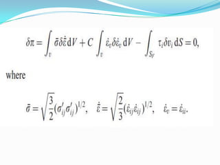
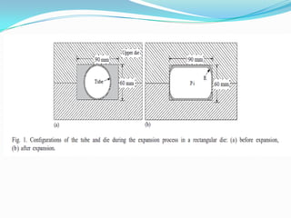
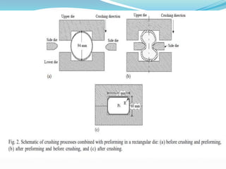
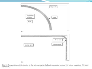
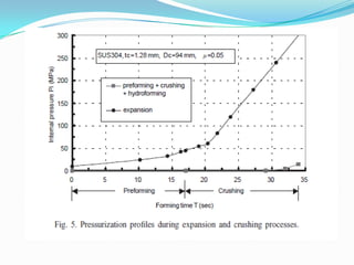
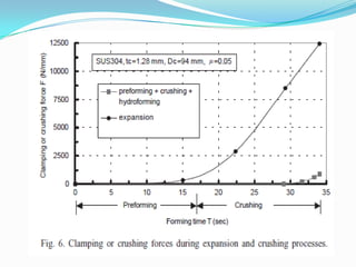
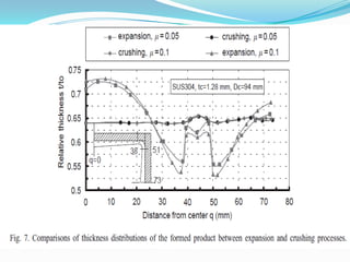
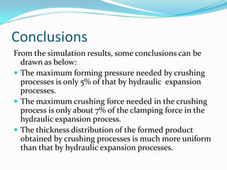
Presented by
Khushboo Shrivastava
Roll No. 123370001
Aim
 Use the Finite Element Method to explore the plastic
flow pattern of a circular tube that is hydraulically
expanded or crushed into a rectangular cross-section.
DEFORM
 The plastic flow patterns of the forming tube and the
thickness distribution of the formed product are
explored while a circular tube is expanded or crushed
into a rectangular cross-section, using a commercially
available FE code “DEFORM”.
Finite element modeling
 An implicit and static FE code “DEFORM”
 The finite element code is based on the flow
formulation approach using an updated Lagrange
procedure. The basic equation for the finite element
formulation from the variational approach is
Finite Element Simulations
Assumptions
 Die is rigid, the tube is rigid-plastic,
 The plastic deformation of the tube is under a plane
strain state, and the interface between the tube
 Die has a constant friction coefficient
 The flow stress of the tube material of SUS 304 is
assumed to be expressed by a power law of its
equivalent strain, i.e.σ=Ke^n, where K = 1452 MPa is
the strength coefficient and n = 0.6 is the
strain-hardening exponent.
Modelling Parameter
 Four-node isoparametric elements are used.
 The tube is divided into about 1000 elements, and
there are six layers of elements in the thickness
direction.
 The configurations of the meshes in the tube before
crushing and preforming are shown in
Fig.
Iteration Methods
 Direct iteration methods
Generate a good initial guess for the Newton
Raphson method
 Newton-Raphson:
Speedy final convergence
Simulation works for expansion
 The upper die is always in contact with the bottom die
without movement.
 The internal pressure input into the tube is increased
gradually. Following the increase of the internal
pressure, the tube comes in contact with the short
sides of the die and then the corner radius of the free
bulged region, R, decreases. When the programmed
internal pressure reaches 300 MPa, the simulation is
stopped, and the corner radius and the thickness
distribution of the formed product are
measured.
Simulation works for crushing
 The dimension of the upper die is the same as that for
the expansion process. The step increment is set to be
0:01 s. At the beginning and early stage of the crushing
process, no internal pressure is input into the tube to
make the tube expanded outwards. On the contrary,
two side dies with a radius of 15 mm at the left and
right sides of the tube are used to push the tube
inwards to prevent the tube from being pinched by the
upper and lower dies as the upper die goes downwards.
Simulation works for crushing
 After the side dies move 17 mm inwards, as shown in
Fig. 4(b), the side dies move backwards immediately
and then the crushing process starts. As the upper die
is ready to touch the lower die, a gradually increased
pressure is input into the tube to calibrate the tube
and make the tube material 1ow into the corners of the
die as much as possible. The crushed and hydroformed
product is shown in Fig. 4(d).
Results from the simulation
Conclusions
From the simulation results, some conclusions can be
drawn as below:
 The maximum forming pressure needed by crushing
processes is only 5% of that by hydraulic expansion
processes.
 The maximum crushing force needed in the crushing
process is only about 7% of the clamping force in the
hydraulic expansion process.
 The thickness distribution of the formed product
obtained by crushing processes is much more uniform
than that by hydraulic expansion processes.
Conclusions
 The expansion process is a very simple forming process that
does not need extra equipment, such as the side dies and
cylinders, or a procedure control for the internal pressure
and movement of the dies. However, it needs a large press
machine and a high-pressure hydraulic system.
 By introducing the crushing process into the hydroforming
processes, the clamping forces and forming pressures
can be greatly reduced. Furthermore, highly uniform
thickness distributions of the formed products
can be obtained.
References
 F. Dohmann, Ch. Hartl, Tube hydroforming: research
and practical application, J. Mater. Proc. Technol. 71
(1997) 174–186
 Finite element analysis of tube hydroforming
processes in a rectangular die Yeong-Maw Hwanga; ∗,
Taylan Altanb
Thank you

Tube hydroforming

  • 1.
  • 2.
    Aim  Use theFinite Element Method to explore the plastic flow pattern of a circular tube that is hydraulically expanded or crushed into a rectangular cross-section.
  • 3.
    DEFORM  The plasticflow patterns of the forming tube and the thickness distribution of the formed product are explored while a circular tube is expanded or crushed into a rectangular cross-section, using a commercially available FE code “DEFORM”.
  • 4.
    Finite element modeling An implicit and static FE code “DEFORM”  The finite element code is based on the flow formulation approach using an updated Lagrange procedure. The basic equation for the finite element formulation from the variational approach is
  • 8.
    Finite Element Simulations Assumptions Die is rigid, the tube is rigid-plastic,  The plastic deformation of the tube is under a plane strain state, and the interface between the tube  Die has a constant friction coefficient  The flow stress of the tube material of SUS 304 is assumed to be expressed by a power law of its equivalent strain, i.e.σ=Ke^n, where K = 1452 MPa is the strength coefficient and n = 0.6 is the strain-hardening exponent.
  • 9.
    Modelling Parameter  Four-nodeisoparametric elements are used.  The tube is divided into about 1000 elements, and there are six layers of elements in the thickness direction.  The configurations of the meshes in the tube before crushing and preforming are shown in Fig.
  • 11.
    Iteration Methods  Directiteration methods Generate a good initial guess for the Newton Raphson method  Newton-Raphson: Speedy final convergence
  • 13.
    Simulation works forexpansion  The upper die is always in contact with the bottom die without movement.  The internal pressure input into the tube is increased gradually. Following the increase of the internal pressure, the tube comes in contact with the short sides of the die and then the corner radius of the free bulged region, R, decreases. When the programmed internal pressure reaches 300 MPa, the simulation is stopped, and the corner radius and the thickness distribution of the formed product are measured.
  • 14.
    Simulation works forcrushing  The dimension of the upper die is the same as that for the expansion process. The step increment is set to be 0:01 s. At the beginning and early stage of the crushing process, no internal pressure is input into the tube to make the tube expanded outwards. On the contrary, two side dies with a radius of 15 mm at the left and right sides of the tube are used to push the tube inwards to prevent the tube from being pinched by the upper and lower dies as the upper die goes downwards.
  • 15.
    Simulation works forcrushing  After the side dies move 17 mm inwards, as shown in Fig. 4(b), the side dies move backwards immediately and then the crushing process starts. As the upper die is ready to touch the lower die, a gradually increased pressure is input into the tube to calibrate the tube and make the tube material 1ow into the corners of the die as much as possible. The crushed and hydroformed product is shown in Fig. 4(d).
  • 17.
    Results from thesimulation
  • 22.
    Conclusions From the simulationresults, some conclusions can be drawn as below:  The maximum forming pressure needed by crushing processes is only 5% of that by hydraulic expansion processes.  The maximum crushing force needed in the crushing process is only about 7% of the clamping force in the hydraulic expansion process.  The thickness distribution of the formed product obtained by crushing processes is much more uniform than that by hydraulic expansion processes.
  • 23.
    Conclusions  The expansionprocess is a very simple forming process that does not need extra equipment, such as the side dies and cylinders, or a procedure control for the internal pressure and movement of the dies. However, it needs a large press machine and a high-pressure hydraulic system.  By introducing the crushing process into the hydroforming processes, the clamping forces and forming pressures can be greatly reduced. Furthermore, highly uniform thickness distributions of the formed products can be obtained.
  • 24.
    References  F. Dohmann,Ch. Hartl, Tube hydroforming: research and practical application, J. Mater. Proc. Technol. 71 (1997) 174–186  Finite element analysis of tube hydroforming processes in a rectangular die Yeong-Maw Hwanga; ∗, Taylan Altanb
  • 25.