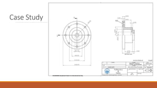
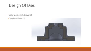
1) The document summarizes a case study for forging a part made of C45 steel using finite element analysis to simulate the forging process.
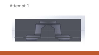
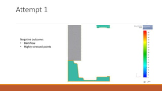
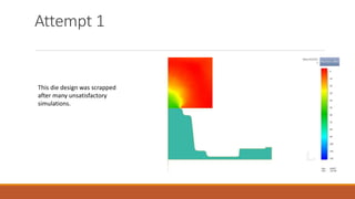
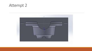
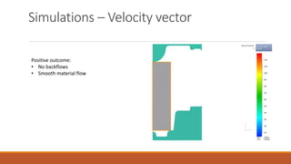
2) The first die design attempt was unsuccessful, with issues like backflow and highly stressed points. The second die design attempt showed promising results with smooth material flow and an evenly distributed maximum stress of 130MPa.
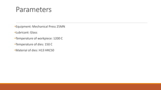
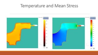
3) Finite element simulations of the second die design indicated no issues, with optimal load and temperature distributions and a maximum required load of 21MN, within the press's 25MN capacity.