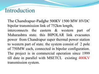
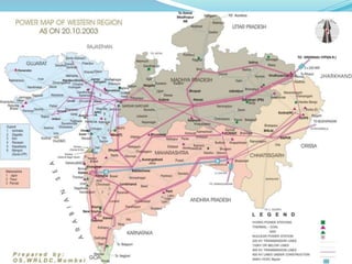
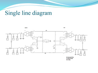
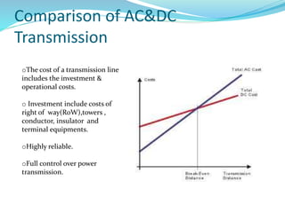
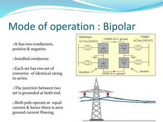
Presented By:
Mr.MANISH
.U.CHAVAN
Seat No. T120212508
AISSMS’S COLLEGE OF ENGINEERING
PUNE
Department of Electrical Engineering
Guided By:
Prof.Mrs.S.Y.CHAVAN
Introduction
The Chandrapur-Padghe 500KV 1500 MW HVDC
bipolar transmission link of 752km length,
interconnects the eastern & western part of
Maharashtra state. this BIPOLAR link evacuates
power from Chandrapur super thermal power station
to western part of state. the system consist of 2 pole
of 750MW each, connected in bipolar configuration.
The project is in commercial operation since 1999
till date in parallel with MSETCL existing 400KV
transmission system.
Rated Power 1500 MW
DC Voltage � 500 kV
AC System Voltage Chandrapur 400 kV
Dadri 400 kV Padghe 400 kV
Overload Capacity low ambient 1650 MW
2h 1650 MW
5s 2000 MW
Maximum Continuous Current 1786 A
Thyristor Valves
Thyristor Size 45 sq. cm.
Valve Type 3 quadruple valves per converter
Cooling Water
Converter Transformers
Number in each terminal 6 nos. single-phase 3-winding (+1 spare)
Rated Power 298.6 MVA
Smoothing Reactor 360 mH oil insulated and insulated per pole
AC Filters 4 nos. 200 MVAR in each station
Single line diagram
Comparison of AC&DC
Transmission
oThe cost of a transmission line
includes the investment &
operational costs.
o Investment include costs of
right of way(RoW),towers ,
conductor, insulator and
terminal equipments.
oHighly reliable.
oFull control over power
transmission.
oInitial cost is high but overall cost is low than
AC transmission system.
oLess corona effect.
oNo skin effect.
oCan interconnect diff power system.
oFive times more energy transmits than AC
system.
oSystem is much stable.
oHigh transmission effeciency
Mode of operation : Bipolar
oIt has two conductors,
positive & negative.
obundled conductor.
oEach set has two set of
converter of identical rating
in series.
oThe junction between two
set is grounded at both end.
oBoth pole operate at equal
current & hence there is zero
ground current flowing.
Financing
 WORLD BANK
 POWER FINANCE CORPORATION
 ABB
 BHEL
 GRANT FROM SWEDISH AID AGENCY SIDA
 SOFT LOAN FROM SWEDISH AGENCY BITS
 FINANCE FROM INDUSTRIAL BANK
,GUARANTEED BY GERMAN CREDIT
INSURANCE,HERMES
Main circuit equipments:
Converters & Inverters
o They perform AC/DC and DC/AC conversion.
oThey consist of valve bridge and transformer.
oValve bridge consist of high voltage valve connected
in a 6 pulse or 12 pulse arrangement.
oTransformer are ungrounded such that dc system will
be able to establish its own reference to ground .
Smoothing reactors
oThey decrease harmonics in voltage & current in DC
line.
oThey prevent commutation failure in inverter.
oPrevent current from being disconnected for light
load.
Filters
oConverters generate harmonics in voltage &
current.
oThese cause overheating of capacitor.
oFilters are use to mitigate these harmonics.
oAC & DC FILTERS
Converter transformer
oThey are design to withstand DC voltage
stress .
&increase eddy current losses due to harmonic
current.
oFault arise is by DC magnetization of core
due to unsymmetrical firing of valve.
Reactive power source
oConverter station require reactive power that
is dependent on active power loading (anout
50-60%of active power).
oDue to the fact that current drawn by LCC can
only lag supply voltage.
DC switchgear
oIt is modified AC equipment used to interrupt
small DC current.
oUsed for protection and measurement.
oIt include DC current& voltage transducers.
Thyrister valves
oThey make conversion from AC into DC,hence
central component of any converter station.
FACTS
AUXILIARY POWER SYSTEM
oTo achieve desired reliability and availability of an HVDC link.
oIt consist of fully control & protection system with one active
system and one hot standby system.
SCADA
oSupervisory control and data acquisition system.
oSimple fast efficient data retrieval.
oCan monitor 600 signal(analog & digital).
FUTURE OF HVDC
Conclusion
 Less power losses
 No skin effect
 Less corona effect
 Highly stable system
 Can connect two diff power systems
 Less ferranti effect
 Compensation is not required
 Long & underwater power transmission
REFERENCE
 Report of 15th national power system conference (NPSC) IIT bombay
,Dec 2008
 The Chandrapur –Padghe HVDC Bipolar project report of ABB
SWEDEN
 An over view to HVDC line India by Prof. Kusum Tharani
BOOK
• HVDC power transmission system by K.R.Padiyar
WEBSITE
• http://new.abb.com/systems/hvdc/references/chandrapur---padghe
• http://www.bhel.com/product_services/tranmission/hvdc/win3.htm
THANK YOU

A CASE STUDY : CHANDRAPUR-PADGHE HVDC BIPOLE

  • 1.
    Presented By: Mr.MANISH .U.CHAVAN Seat No.T120212508 AISSMS’S COLLEGE OF ENGINEERING PUNE Department of Electrical Engineering Guided By: Prof.Mrs.S.Y.CHAVAN
  • 2.
    Introduction The Chandrapur-Padghe 500KV1500 MW HVDC bipolar transmission link of 752km length, interconnects the eastern & western part of Maharashtra state. this BIPOLAR link evacuates power from Chandrapur super thermal power station to western part of state. the system consist of 2 pole of 750MW each, connected in bipolar configuration. The project is in commercial operation since 1999 till date in parallel with MSETCL existing 400KV transmission system.
  • 4.
    Rated Power 1500MW DC Voltage � 500 kV AC System Voltage Chandrapur 400 kV Dadri 400 kV Padghe 400 kV Overload Capacity low ambient 1650 MW 2h 1650 MW 5s 2000 MW Maximum Continuous Current 1786 A Thyristor Valves Thyristor Size 45 sq. cm. Valve Type 3 quadruple valves per converter Cooling Water Converter Transformers Number in each terminal 6 nos. single-phase 3-winding (+1 spare) Rated Power 298.6 MVA Smoothing Reactor 360 mH oil insulated and insulated per pole AC Filters 4 nos. 200 MVAR in each station
  • 5.
  • 6.
    Comparison of AC&DC Transmission oThecost of a transmission line includes the investment & operational costs. o Investment include costs of right of way(RoW),towers , conductor, insulator and terminal equipments. oHighly reliable. oFull control over power transmission.
  • 7.
    oInitial cost ishigh but overall cost is low than AC transmission system. oLess corona effect. oNo skin effect. oCan interconnect diff power system. oFive times more energy transmits than AC system. oSystem is much stable. oHigh transmission effeciency
  • 8.
    Mode of operation: Bipolar oIt has two conductors, positive & negative. obundled conductor. oEach set has two set of converter of identical rating in series. oThe junction between two set is grounded at both end. oBoth pole operate at equal current & hence there is zero ground current flowing.
  • 9.
    Financing  WORLD BANK POWER FINANCE CORPORATION  ABB  BHEL  GRANT FROM SWEDISH AID AGENCY SIDA  SOFT LOAN FROM SWEDISH AGENCY BITS  FINANCE FROM INDUSTRIAL BANK ,GUARANTEED BY GERMAN CREDIT INSURANCE,HERMES
  • 10.
    Main circuit equipments: Converters& Inverters o They perform AC/DC and DC/AC conversion. oThey consist of valve bridge and transformer. oValve bridge consist of high voltage valve connected in a 6 pulse or 12 pulse arrangement. oTransformer are ungrounded such that dc system will be able to establish its own reference to ground . Smoothing reactors oThey decrease harmonics in voltage & current in DC line. oThey prevent commutation failure in inverter. oPrevent current from being disconnected for light load.
  • 11.
    Filters oConverters generate harmonicsin voltage & current. oThese cause overheating of capacitor. oFilters are use to mitigate these harmonics. oAC & DC FILTERS Converter transformer oThey are design to withstand DC voltage stress . &increase eddy current losses due to harmonic current. oFault arise is by DC magnetization of core due to unsymmetrical firing of valve.
  • 12.
    Reactive power source oConverterstation require reactive power that is dependent on active power loading (anout 50-60%of active power). oDue to the fact that current drawn by LCC can only lag supply voltage. DC switchgear oIt is modified AC equipment used to interrupt small DC current. oUsed for protection and measurement. oIt include DC current& voltage transducers. Thyrister valves oThey make conversion from AC into DC,hence central component of any converter station.
  • 13.
    FACTS AUXILIARY POWER SYSTEM oToachieve desired reliability and availability of an HVDC link. oIt consist of fully control & protection system with one active system and one hot standby system. SCADA oSupervisory control and data acquisition system. oSimple fast efficient data retrieval. oCan monitor 600 signal(analog & digital).
  • 14.
  • 15.
    Conclusion  Less powerlosses  No skin effect  Less corona effect  Highly stable system  Can connect two diff power systems  Less ferranti effect  Compensation is not required  Long & underwater power transmission
  • 16.
    REFERENCE  Report of15th national power system conference (NPSC) IIT bombay ,Dec 2008  The Chandrapur –Padghe HVDC Bipolar project report of ABB SWEDEN  An over view to HVDC line India by Prof. Kusum Tharani BOOK • HVDC power transmission system by K.R.Padiyar WEBSITE • http://new.abb.com/systems/hvdc/references/chandrapur---padghe • http://www.bhel.com/product_services/tranmission/hvdc/win3.htm
  • 17.