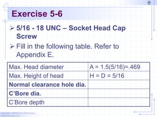
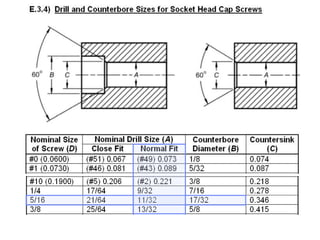
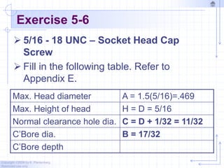
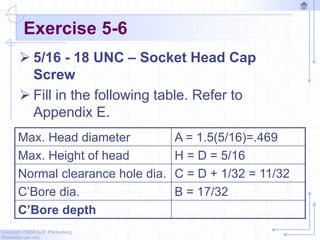
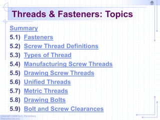
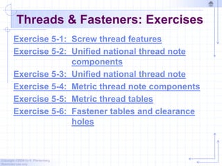
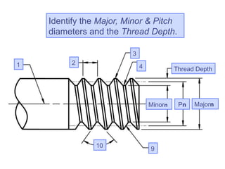
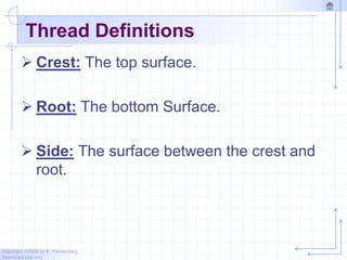
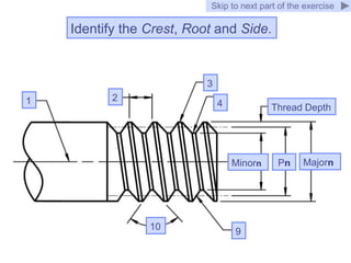
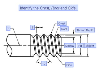
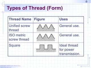
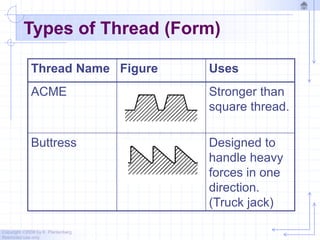
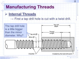
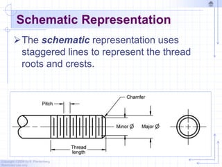
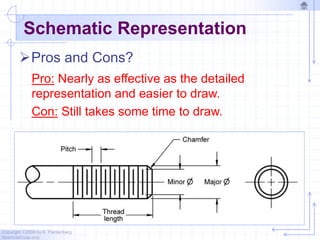
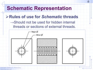
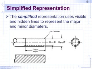
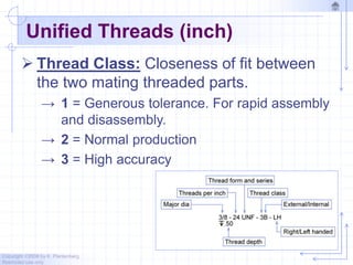
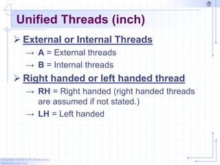
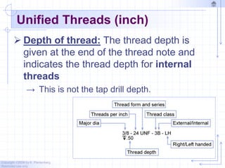
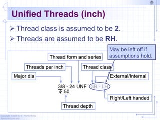
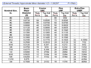
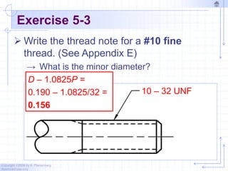
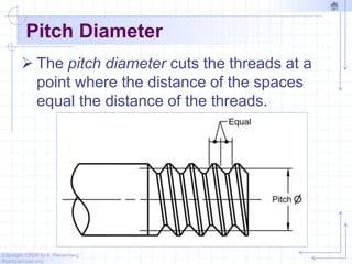
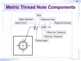
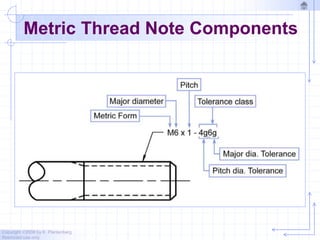
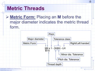
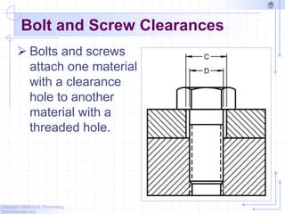
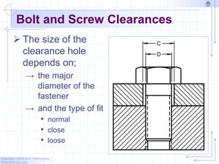
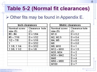
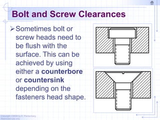
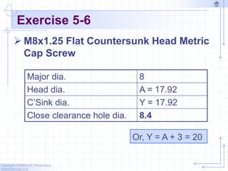
SlideShare a Scribd company logo
1 of 128
Copyright ©2006 by K. Plantenberg
Restricted use only
Chapter 5
Threads and Fasteners
Topics
Exercises
Copyright ©2006 by K. Plantenberg
Restricted use only
Threads & Fasteners: Topics
Summary
5.1) Fasteners
5.2) Screw Thread Definitions
5.3) Types of Thread
5.4) Manufacturing Screw Threads
5.5) Drawing Screw Threads
5.6) Unified Threads
5.7) Metric Threads
5.8) Drawing Bolts
5.9) Bolt and Screw Clearances
Copyright ©2006 by K. Plantenberg
Restricted use only
Threads & Fasteners: Exercises
Exercise 5-1: Screw thread features
Exercise 5-2: Unified national thread note
components
Exercise 5-3: Unified national thread note
Exercise 5-4: Metric thread note components
Exercise 5-5: Metric thread tables
Exercise 5-6: Fastener tables and clearance
holes
Copyright ©2006 by K. Plantenberg
Restricted use only
Threads and Fasteners
Summary
Copyright ©2006 by K. Plantenberg
Restricted use only
Summary
 What will we learn in Chapter 5?
→ How to represent fasteners and threads on
an engineering drawing.
→ How to calculate bolt and screw clearance
holes.
 Key points
→ Threads are represented by thread symbols,
not by a realistic drawing.
Copyright ©2006 by K. Plantenberg
Restricted use only
Threads and Fasteners
5.1) Fasteners
Copyright ©2006 by K. Plantenberg
Restricted use only
Fasteners
 Fasteners include:
→ bolts and nuts (threaded)
→ set screws (threaded)
→ washers
→ keys
→ pins
 Fasteners are not a permanent means
of assembly such as welding or
adhesives.
Copyright ©2006 by K. Plantenberg
Restricted use only
Fasteners
 Fasteners and threaded features must
be specified on your engineering
drawing.
→ Threaded features: Threads are specified in
a thread note.
→ General Fasteners: Purchasing information
must be given to allow the fastener to be
ordered correctly.
Copyright ©2006 by K. Plantenberg
Restricted use only
Threads and Fasteners
5.2) Screw Thread Definitions
Copyright ©2006 by K. Plantenberg
Restricted use only
Thread Definitions
 Screw Thread: A ridge of uniform section
in the form of a helix.
Copyright ©2006 by K. Plantenberg
Restricted use only
Thread Definitions
 External Thread: External threads are on
the outside of a member.
→ A chamfer on the end of the screw thread
makes it easier to engage the nut.
Chamfer
Copyright ©2006 by K. Plantenberg
Restricted use only
Thread Definitions
 External Thread:
→ An external thread is cut using a die or a
lathe.
Copyright ©2006 by K. Plantenberg
Restricted use only
Thread Definitions
 Internal Thread: Internal threads are on
the inside of a member.
→ An internal thread is cut using a tap.
Copyright ©2006 by K. Plantenberg
Restricted use only
Thread Definitions
 Major DIA (D): The largest diameter (For
both internal and external threads).
 Minor DIA (d): The smallest diameter.
 Depth of thread: (D-d)/2
 Pitch DIA (dP): The diameter at which a
line cuts the spaces and threads equally.
Copyright ©2006 by K. Plantenberg
Restricted use only
Exercise 5-1
Screw thread features
8
Identify the Major, Minor & Pitch
diameters and the Thread Depth.
Skip to next part of the exercise
7
1 2
3
4 5
6
10 9
8
8
Identify the Major, Minor & Pitch
diameters and the Thread Depth.
1 2
3
4
Minorn
10 9
Thread Depth
Majorn
Pn
Copyright ©2006 by K. Plantenberg
Restricted use only
Thread Definitions
 Crest: The top surface.
 Root: The bottom Surface.
 Side: The surface between the crest and
root.
Identify the Crest, Root and Side.
Skip to next part of the exercise
1 2
3
4
10 9
8
Minorn
Thread Depth
Majorn
Pn
Identify the Crest, Root and Side.
1 2
Crest
Root
10 Side
8
Minorn
Thread Depth
Majorn
Pn
Copyright ©2006 by K. Plantenberg
Restricted use only
Thread Definitions
 Pitch (P): The distance from a point on a
screw thread to a corresponding point on
the next thread (in/Threads).
 Angle of Thread (A): The angle between
the threads.
Copyright ©2006 by K. Plantenberg
Restricted use only
Thread Definitions
 Screw Axis: The longitudinal centerline.
 Lead: The distance a screw thread
advances axially in one turn.
Identify the Pitch, Screw Axis and Thread Angle.
1 2
10
Crest
Root
Side
8
Minorn
Thread Depth
Majorn
Pn
Identify the Pitch, Screw Axis and Thread Angle.
Axis Pitch
Angle
Crest
Root
Side
8
Minorn
Thread Depth
Majorn
Pn
Copyright ©2006 by K. Plantenberg
Restricted use only
Thread Definitions
 Right Handed Thread: Advances when
turned CW. (Threads are assumed RH
unless specified otherwise.)
 Left Handed Thread: Advances when
turned CCW.
Copyright ©2006 by K. Plantenberg
Restricted use only
Application Question 5-1
 Name an example of a left handed thread.
Left peddle of a bike
Copyright ©2006 by K. Plantenberg
Restricted use only
Threads and Fasteners
5.3) Types of Thread
Copyright ©2006 by K. Plantenberg
Restricted use only
Types of Thread
 There are many different types of
thread forms (shape) available. The
most common are;
→ Unified
→ Metric
Copyright ©2006 by K. Plantenberg
Restricted use only
Types of Thread
 Thread form choice depends on;
→ what it will be used for
→ length of engagement
→ load
→ etc…
Copyright ©2006 by K. Plantenberg
Restricted use only
Types of Thread (Form)
Thread Name Figure Uses
Unified screw
thread
General use.
ISO metric
screw thread
General use.
Square Ideal thread
for power
transmission.
Copyright ©2006 by K. Plantenberg
Restricted use only
Types of Thread (Form)
Thread Name Figure Uses
ACME Stronger than
square thread.
Buttress Designed to
handle heavy
forces in one
direction.
(Truck jack)
Copyright ©2006 by K. Plantenberg
Restricted use only
Threads and Fasteners
5.4) Manufacturing Screw
Threads
Copyright ©2006 by K. Plantenberg
Restricted use only
Manufacturing Threads
 Internal Threads
→ First a tap drill hole is cut with a twist drill.
The tap drill hole
is a little bigger
than the minor
diameter. Why?
Copyright ©2006 by K. Plantenberg
Restricted use only
Manufacturing Threads
 Internal Threads
→Then the threads are cut using a tap.
The tap drill hole
is longer than the
length of the
threads. Why?
Incomplete
threads
Copyright ©2006 by K. Plantenberg
Restricted use only
Manufacturing Threads
 Internal Threads
→Chamfers are sometimes cut to allow for
easy engagement.
Copyright ©2006 by K. Plantenberg
Restricted use only
Manufacturing Threads
 External Threads
→You start with a shaft the same size as the
major diameter.
Copyright ©2006 by K. Plantenberg
Restricted use only
Manufacturing Threads
 External Threads
→The threads are then cut using a die or on a
lathe.
Copyright ©2006 by K. Plantenberg
Restricted use only
Threads and Fasteners
5.5) Drawing Screw Threads
Copyright ©2006 by K. Plantenberg
Restricted use only
Drawing Screw Threads
 There are three methods of
representing screw threads on a
drawing.
→ Detailed
→ Schematic
→ Simplified
 Screw thread representation present in
this chapter is in accordance with the
ASME Y14.6-2001 standard.
Copyright ©2006 by K. Plantenberg
Restricted use only
Detailed Representation
A detailed representation is a close
approximation of the appearance of an
actual screw thread.
Copyright ©2006 by K. Plantenberg
Restricted use only
Detailed Representation
Pros and Cons?
Pro: Looks good and clearly represents a thread.
Con: Takes a long time to draw.
Copyright ©2006 by K. Plantenberg
Restricted use only
Schematic Representation
The schematic representation uses
staggered lines to represent the thread
roots and crests.
Copyright ©2006 by K. Plantenberg
Restricted use only
Schematic Representation
Pros and Cons?
Pro: Nearly as effective as the detailed
representation and easier to draw.
Con: Still takes some time to draw.
Copyright ©2006 by K. Plantenberg
Restricted use only
Schematic Representation
Rules of use for Schematic threads
→Should not be used for hidden internal
threads or sections of external threads.
Copyright ©2006 by K. Plantenberg
Restricted use only
Simplified Representation
 The simplified representation uses visible
and hidden lines to represent the major
and minor diameters.
Copyright ©2006 by K. Plantenberg
Restricted use only
Simplified Representation
 Pros and Cons?
Pro: Simple and fast to draw.
Con: Doesn’t look like a thread.
Copyright ©2006 by K. Plantenberg
Restricted use only
Simplified Internal Threads
Copyright ©2006 by K. Plantenberg
Restricted use only
Simplified Internal Threads
Copyright ©2006 by K. Plantenberg
Restricted use only
Drawing Screw Threads
 Thread tables in the appendix can be
used to look up value for the;
→ Pitch
→ Minor diameter
→ Tap drill diameter
 If screw thread tables are not available,
the minor diameter can be approximated
as 75% of the major diameter.
Copyright ©2006 by K. Plantenberg
Restricted use only
Threads and Fasteners
5.6) Unified Threads
Copyright ©2006 by K. Plantenberg
Restricted use only
Unified Threads (inch)
 After drawing a thread, we need to identify
the size and thread form in a thread note.
Thread Note
Copyright ©2006 by K. Plantenberg
Restricted use only
Unified Thread Note Components
Copyright ©2006 by K. Plantenberg
Restricted use only
Unified Threads (inch)
 Major Diameter: The largest diameter.
 Threads per inch: Number of threads per
inch for a particular diameter.
→ Equal to one over the pitch (1/P).
Copyright ©2006 by K. Plantenberg
Restricted use only
Unified Threads (inch)
 Thread Form and Series: The shape of
the thread cut.
→ UNC = Unified National coarse.
• For general use.
→ UNF = Unified National fine.
• Used when high degree of tightness is required.
→ UNEF = Unified National extra fine.
• Used when length of engagement is limited
(Example: Sheet metal).
Copyright ©2006 by K. Plantenberg
Restricted use only
Unified Threads (inch)
 Thread Class: Closeness of fit between
the two mating threaded parts.
→ 1 = Generous tolerance. For rapid assembly
and disassembly.
→ 2 = Normal production
→ 3 = High accuracy
Copyright ©2006 by K. Plantenberg
Restricted use only
Unified Threads (inch)
 External or Internal Threads
→ A = External threads
→ B = Internal threads
 Right handed or left handed thread
→ RH = Right handed (right handed threads
are assumed if not stated.)
→ LH = Left handed
Copyright ©2006 by K. Plantenberg
Restricted use only
Unified Threads (inch)
 Depth of thread: The thread depth is
given at the end of the thread note and
indicates the thread depth for internal
threads
→ This is not the tap drill depth.
Copyright ©2006 by K. Plantenberg
Restricted use only
Unified Threads (inch)
 Thread class is assumed to be 2.
 Threads are assumed to be RH.
May be left off if
assumptions hold.
Copyright ©2006 by K. Plantenberg
Restricted use only
Exercise 5-2
Unified National thread note
components
Copyright ©2006 by K. Plantenberg
Restricted use only
Exercise 5-2
 Identify the different components of the
following Unified National thread note.
 1/4 – 20 UNC – 2A – RH
1/4
20
UNC
2
A
RH
.25 inch Major DIA
20 threads per inch (P = 1/20 = .05)
Thread form & series – UN Coarse
Thread Class – Normal Production
External Threads
Right Handed Threads
Copyright ©2006 by K. Plantenberg
Restricted use only
Exercise 5-2
 Identify the different components of the
following Unified National thread note.
 1/4 – 28 UNF – 3B – LH
1/4
28
UNF
3
B
LH
.25 inch Major DIA
28 threads per inch (P = 1/28 = .036)
Thread form & series – UN Fine
Thread Class – High Accuracy
Internal Threads
Left Handed Threads
Copyright ©2006 by K. Plantenberg
Restricted use only
Unified National Thread Tables
 Standard screw thread tables are
available in order to look up the:
→ Major diameter
→ Threads per inch
→ Minor diameter or Tap drill size.
 Thread tables are located in Appendix E.
Copyright ©2006 by K. Plantenberg
Restricted use only
Exercise 5-3
Unified National thread note
Copyright ©2006 by K. Plantenberg
Restricted use only
Exercise 5-3
 Write the thread note for a #10 fine
thread. (See Appendix E)
Copyright ©2006 by K. Plantenberg
Restricted use only
Exercise 5-3
 Write the thread note for a #10 fine
thread. (See Appendix E)
10 – 32 UNF
Copyright ©2006 by K. Plantenberg
Restricted use only
Exercise 5-3
 Write the thread note for a #10 fine
thread. (See Appendix E)
→ Is the major diameter 10 inches? No
10 – 32 UNF
Copyright ©2006 by K. Plantenberg
Restricted use only
Exercise 5-3
 Write the thread note for a #10 fine
thread. (See Appendix E)
→ Is the major diameter 10 inches? 0.190
10 – 32 UNF
Copyright ©2006 by K. Plantenberg
Restricted use only
Exercise 5-3
 Write the thread note for a #10 fine
thread. (See Appendix E)
→ What is the minor diameter?
10 – 32 UNF
Copyright ©2006 by K. Plantenberg
Restricted use only
Exercise 5-3
 Write the thread note for a #10 fine
thread. (See Appendix E)
→ What is the minor diameter?
10 – 32 UNF
D – 1.0825P =
0.190 – 1.0825/32 =
0.156
Copyright ©2006 by K. Plantenberg
Restricted use only
Threads and Fasteners
5.7) Metric Threads
Copyright ©2006 by K. Plantenberg
Restricted use only
Metric Threads
 The metric thread note can contain a
pitch diameter tolerance.
 What is the pitch diameter? Let’s see.
Copyright ©2006 by K. Plantenberg
Restricted use only
Pitch Diameter
 The pitch diameter cuts the threads at a
point where the distance of the spaces
equal the distance of the threads.
Copyright ©2006 by K. Plantenberg
Restricted use only
Metric Thread Note Components
Copyright ©2006 by K. Plantenberg
Restricted use only
Metric Thread Note Components
Copyright ©2006 by K. Plantenberg
Restricted use only
Metric Threads
 Metric Form: Placing an M before the
major diameter indicates the metric thread
form.
Copyright ©2006 by K. Plantenberg
Restricted use only
Metric Threads
 Major Diameter: The largest diameter
 Pitch: (P) Millimeters per thread.
Copyright ©2006 by K. Plantenberg
Restricted use only
Metric Threads
 Tolerance Class: It describes the
looseness or tightness of fit between the
internal and external threads.
Number = Tolerance grade
Letter = Tolerance position
Copyright ©2006 by K. Plantenberg
Restricted use only
Metric Threads
 Tolerance Class:
→ Tolerance Grade: Smaller numbers indicate
a tighter fit.
→ Tolerance Position: Specifies the amount of
allowance.
• Upper case letters = internal threads
• Lower case letters = external threads.
Copyright ©2006 by K. Plantenberg
Restricted use only
Metric Threads
 Tolerance Class: Two classes of metric
thread fits are generally used.
→ 6H/6g = General purpose
→ 6H/5g6g = Closer fit.
→ A tolerance class of 6H/6g is assumed if it is
not specified.
Copyright ©2006 by K. Plantenberg
Restricted use only
Metric Threads
 Right handed or Left handed thread:
→ RH = Right handed (right handed threads
are assumed if not stated.)
→ LH = Left handed
Copyright ©2006 by K. Plantenberg
Restricted use only
Metric Threads
 Depth of thread: It indicates the thread
depth for internal threads, not the tap drill
depth.
Copyright ©2006 by K. Plantenberg
Restricted use only
Metric Thread Note
 A tolerance class of 6H/6g is assumed.
 Threads are assumed to be RH.
May be left off if
assumptions hold.
Copyright ©2006 by K. Plantenberg
Restricted use only
Exercise 5-4
Metric thread note components
Copyright ©2006 by K. Plantenberg
Restricted use only
Exercise 5-4
 Identify the different components of the
following metric thread notes.
 M10 x 1.5 – 4h6h – RH
M
10
1.5
4h
6h
Int. or Ext.
RH
Metric Form
10 mm Major DIA
Pitch – mm/threads
Pitch DIA tolerance
Minor DIA tolerance
External
Right handed threads
Copyright ©2006 by K. Plantenberg
Restricted use only
Exercise 5-4
 Identify the different components of the
following metric thread notes.
 M10 x 1.25 – 5H6H – LH
M
10
1.25
5H
6H
Int. or Ext.
LH
Metric Form
10 mm Major DIA
Pitch – mm/threads
Pitch DIA tolerance
Minor DIA tolerance
Internal
Left handed threads
Copyright ©2006 by K. Plantenberg
Restricted use only
Metric Thread Tables
 Standard screw thread tables are
available in order to look up the;
→ Major diameter
→ Pitch
→ Tap drill size or Minor diameter
 Thread tables are located in Appendix E.
Copyright ©2006 by K. Plantenberg
Restricted use only
Exercise 5-5
Metric thread tables
Copyright ©2006 by K. Plantenberg
Restricted use only
Exercise 5-5
 For a n16 internal metric thread, what are
the;
→ two available pitches,
→ the tap drill diameter,
→ and the corresponding minor diameter for
the mating external threads.
Find this page.
Copyright ©2006 by K. Plantenberg
Restricted use only
Exercise 5-5
 For a n16 internal metric thread.
Pitch Tap drill DIA Minor DIA
(External)
2
1.5
14
14.5
13.6
14.2
Copyright ©2006 by K. Plantenberg
Restricted use only
Exercise 5-5
 For a n16 internal metric thread.
 Which has the finer thread?
→ Pitch = 2
→ Pitch = 1.5
Copyright ©2006 by K. Plantenberg
Restricted use only
Exercise 5-5
 Write the thread note for a 16 mm
diameter coarse thread.
M16 x 2
Copyright ©2006 by K. Plantenberg
Restricted use only
Threads and Fasteners
5.8) Drawing Bolts
Copyright ©2006 by K. Plantenberg
Restricted use only
Drawing Bolts
 D represents the
major diameter.
 Nuts are drawn in
a similar fashion.
Copyright ©2006 by K. Plantenberg
Restricted use only
Threads and Fasteners
5.9) Bolt and Screw Clearances
Copyright ©2006 by K. Plantenberg
Restricted use only
Bolt and Screw Clearances
 Bolts and screws
attach one material
with a clearance
hole to another
material with a
threaded hole.
Copyright ©2006 by K. Plantenberg
Restricted use only
Bolt and Screw Clearances
 The size of the
clearance hole
depends on;
→ the major
diameter of the
fastener
→ and the type of fit
• normal
• close
• loose
Copyright ©2006 by K. Plantenberg
Restricted use only
Table 5-2 (Normal fit clearances)
 Other fits may be found in Appendix E.
Copyright ©2006 by K. Plantenberg
Restricted use only
Bolt and Screw Clearances
Sometimes bolt or
screw heads need to
be flush with the
surface. This can be
achieved by using
either a counterbore
or countersink
depending on the
fasteners head shape.
Copyright ©2006 by K. Plantenberg
Restricted use only
Bolt and Screw Clearances
 Counterbores:
Counterbores are
holes designed to
recess bolt or screw
heads below the
surface of a part.
Typically,
CH = H + 1/16 (1.5 mm)
and
C1 = D1 + 1/8 (3 mm)
Copyright ©2006 by K. Plantenberg
Restricted use only
Bolt and Screw Clearances
 Countersink:
Countersinks are
angled holes that are
designed to recess
screws with angled
heads.
Typically,
C1 = D1 + 1/8 (3 mm)
Appendix E gives other
counterbore, countersink
and shaft clearance holes.
Copyright ©2006 by K. Plantenberg
Restricted use only
Exercise 5-6
Fastener tables and clearance
holes
Copyright ©2006 by K. Plantenberg
Restricted use only
Exercise 5-6
 What is the normal fit clearance hole
diameter for the following nominal bolt
sizes.
Nominal
size
Clearance
hole
1/4
3/4
9/32
13/16
Copyright ©2006 by K. Plantenberg
Restricted use only
Exercise 5-6
 A 5/16 - 18 UNC – Socket Head Cap
Screw needs to go through a piece of
metal in order to screw into a plate below.
 The head of the screw should be flush
with the surface.
Copyright ©2006 by K. Plantenberg
Restricted use only
Exercise 5-6
 5/16 - 18 UNC – Socket Head Cap
Screw
 Fill in the following table. Refer to
Appendix E.
Head diameter
Height of head
Normal clearance hole dia.
C’Bore dia.
C’Bore depth
D = 5/16
Copyright ©2006 by K. Plantenberg
Restricted use only
Exercise 5-6
 5/16 - 18 UNC – Socket Head Cap
Screw
 Fill in the following table. Refer to
Appendix E.
Max. Head diameter A = 1.5(5/16)=0.469
Max. Height of head H = D = 5/16
Normal clearance hole dia.
C’Bore dia.
C’Bore depth
Copyright ©2006 by K. Plantenberg
Restricted use only
Exercise 5-6
 5/16 - 18 UNC – Socket Head Cap
Screw
 Fill in the following table. Refer to
Appendix E.
Max. Head diameter A = 1.5(5/16)=.469
Max. Height of head H = D = 5/16
Normal clearance hole dia.
C’Bore dia.
C’Bore depth
Copyright ©2006 by K. Plantenberg
Restricted use only
Exercise 5-6
 5/16 - 18 UNC – Socket Head Cap
Screw
 Fill in the following table. Refer to
Appendix E.
Max. Head diameter A = 1.5(5/16)=.469
Max. Height of head H = D = 5/16
Normal clearance hole dia. C = D + 1/32 = 11/32
C’Bore dia. B = 17/32
C’Bore depth >H (H+1/8 = 7/16)
Copyright ©2006 by K. Plantenberg
Restricted use only
Exercise 5-6
 An M8x1.25 Flat Countersunk Head
Metric Cap Screw needs to go through a
piece of metal in order to screw into a
plate below.
 The clearance hole needs to be close and
the head needs to be flush with the
surface.
 What should the countersink diameter and
clearance hole diameter be?
Copyright ©2006 by K. Plantenberg
Restricted use only
Exercise 5-6
 M8x1.25 Flat Countersunk Head Metric
Cap Screw
Major dia.
Head dia.
C’Sink dia.
Close clearance hole dia.
Copyright ©2006 by K. Plantenberg
Restricted use only
Exercise 5-6
 M8x1.25 Flat Countersunk Head Metric
Cap Screw
Major dia. 8
Head dia.
C’Sink dia.
Close clearance hole dia.
Copyright ©2006 by K. Plantenberg
Restricted use only
Exercise 5-6
 M8x1.25 Flat Countersunk Head Metric
Cap Screw
Major dia. 8
Head dia.
C’Sink dia.
Close clearance hole dia.
Copyright ©2006 by K. Plantenberg
Restricted use only
Exercise 5-6
 M8x1.25 Flat Countersunk Head Metric
Cap Screw
Major dia. 8
Head dia. A = 17.92
C’Sink dia.
Close clearance hole dia.
Copyright ©2006 by K. Plantenberg
Restricted use only
Exercise 5-6
 M8x1.25 Flat Countersunk Head Metric
Cap Screw
Major dia. 8
Head dia. A = 17.92
C’Sink dia.
Close clearance hole dia.
Copyright ©2006 by K. Plantenberg
Restricted use only
Exercise 5-6
 M8x1.25 Flat Countersunk Head Metric
Cap Screw
Major dia. 8
Head dia. A = 17.92
C’Sink dia. Y = 17.92
Close clearance hole dia.
Or, Y = A + 3 = 20
Copyright ©2006 by K. Plantenberg
Restricted use only
Exercise 5-6
 M8x1.25 Flat Countersunk Head Metric
Cap Screw
Major dia. 8
Head dia. A = 17.92
C’Sink dia. Y = 17.92
Close clearance hole dia.
Or, Y = A + 3 = 20
Copyright ©2006 by K. Plantenberg
Restricted use only
Exercise 5-6
 M8x1.25 Flat Countersunk Head Metric
Cap Screw
Major dia. 8
Head dia. A = 17.92
C’Sink dia. Y = 17.92
Close clearance hole dia. 8.4
Or, Y = A + 3 = 20
Copyright ©2006 by K. Plantenberg
Restricted use only
Threads and Fasteners
The End

More Related Content

What's hot

Chapter 6 sectioning - 2010
Chapter 6   sectioning - 2010Chapter 6   sectioning - 2010
Chapter 6 sectioning - 2010Shelly Wilke
 
Screw thread measurement
Screw thread measurementScrew thread measurement
Screw thread measurementnmahi96
 
Engineering Drawing: Chapter 11 thread fastener
Engineering Drawing: Chapter 11 thread fastenerEngineering Drawing: Chapter 11 thread fastener
Engineering Drawing: Chapter 11 thread fastenermokhtar
 
jigs & fixtures, gear and thread manufacturing,manufacturing processes,Produ...
 jigs & fixtures, gear and thread manufacturing,manufacturing processes,Produ... jigs & fixtures, gear and thread manufacturing,manufacturing processes,Produ...
jigs & fixtures, gear and thread manufacturing,manufacturing processes,Produ...Prof.Mayur Modi
 
Chapter 4 dimensioning - 2010
Chapter 4   dimensioning - 2010Chapter 4   dimensioning - 2010
Chapter 4 dimensioning - 2010Shelly Wilke
 
Lathe-Types, Parts, Feed Mechanisms, Specifications,Lathe Accessories and Att...
Lathe-Types, Parts, Feed Mechanisms, Specifications,Lathe Accessories and Att...Lathe-Types, Parts, Feed Mechanisms, Specifications,Lathe Accessories and Att...
Lathe-Types, Parts, Feed Mechanisms, Specifications,Lathe Accessories and Att...rajguptanitw
 
Theory of machine
Theory of machine Theory of machine
Theory of machine ahirehemant
 
Types of fasteners and fixings
Types of fasteners and fixingsTypes of fasteners and fixings
Types of fasteners and fixingsThe WDS Group
 
Chapter 14 pictorials - 2010
Chapter 14   pictorials - 2010Chapter 14   pictorials - 2010
Chapter 14 pictorials - 2010Shelly Wilke
 
Bearing and Sliding contact bearings
Bearing and Sliding contact bearingsBearing and Sliding contact bearings
Bearing and Sliding contact bearingsdodi mulya
 
Engineering drawing chapter 03 orthographic projection.
Engineering drawing chapter 03 orthographic projection.Engineering drawing chapter 03 orthographic projection.
Engineering drawing chapter 03 orthographic projection.Talha Mughal
 
Chapter 3 sectioning
Chapter 3   sectioningChapter 3   sectioning
Chapter 3 sectioninghokiemac
 
Sheet metal design.pptx
Sheet metal design.pptxSheet metal design.pptx
Sheet metal design.pptxnathajishelke1
 
Types of nuts and bolts
Types of nuts and boltsTypes of nuts and bolts
Types of nuts and boltsRayon Johnson
 
Limit , Fits and Tolerance
Limit , Fits and ToleranceLimit , Fits and Tolerance
Limit , Fits and ToleranceJaspreet Singh
 

What's hot (20)

Chapter 6 sectioning - 2010
Chapter 6   sectioning - 2010Chapter 6   sectioning - 2010
Chapter 6 sectioning - 2010
 
Fasteners (2)
Fasteners (2)Fasteners (2)
Fasteners (2)
 
Screw thread measurement
Screw thread measurementScrew thread measurement
Screw thread measurement
 
Engineering Drawing: Chapter 11 thread fastener
Engineering Drawing: Chapter 11 thread fastenerEngineering Drawing: Chapter 11 thread fastener
Engineering Drawing: Chapter 11 thread fastener
 
Shaper
ShaperShaper
Shaper
 
jigs & fixtures, gear and thread manufacturing,manufacturing processes,Produ...
 jigs & fixtures, gear and thread manufacturing,manufacturing processes,Produ... jigs & fixtures, gear and thread manufacturing,manufacturing processes,Produ...
jigs & fixtures, gear and thread manufacturing,manufacturing processes,Produ...
 
Chapter 4 dimensioning - 2010
Chapter 4   dimensioning - 2010Chapter 4   dimensioning - 2010
Chapter 4 dimensioning - 2010
 
Lathe-Types, Parts, Feed Mechanisms, Specifications,Lathe Accessories and Att...
Lathe-Types, Parts, Feed Mechanisms, Specifications,Lathe Accessories and Att...Lathe-Types, Parts, Feed Mechanisms, Specifications,Lathe Accessories and Att...
Lathe-Types, Parts, Feed Mechanisms, Specifications,Lathe Accessories and Att...
 
Theory of machine
Theory of machine Theory of machine
Theory of machine
 
Metrology and Measuremenrt
Metrology and MeasuremenrtMetrology and Measuremenrt
Metrology and Measuremenrt
 
Types of fasteners and fixings
Types of fasteners and fixingsTypes of fasteners and fixings
Types of fasteners and fixings
 
Chapter 14 pictorials - 2010
Chapter 14   pictorials - 2010Chapter 14   pictorials - 2010
Chapter 14 pictorials - 2010
 
Bearing and Sliding contact bearings
Bearing and Sliding contact bearingsBearing and Sliding contact bearings
Bearing and Sliding contact bearings
 
Engineering drawing chapter 03 orthographic projection.
Engineering drawing chapter 03 orthographic projection.Engineering drawing chapter 03 orthographic projection.
Engineering drawing chapter 03 orthographic projection.
 
jigs and fixtures_MP
jigs and fixtures_MPjigs and fixtures_MP
jigs and fixtures_MP
 
Chapter 3 sectioning
Chapter 3   sectioningChapter 3   sectioning
Chapter 3 sectioning
 
Sheet metal design.pptx
Sheet metal design.pptxSheet metal design.pptx
Sheet metal design.pptx
 
Assembly drawing
Assembly drawingAssembly drawing
Assembly drawing
 
Types of nuts and bolts
Types of nuts and boltsTypes of nuts and bolts
Types of nuts and bolts
 
Limit , Fits and Tolerance
Limit , Fits and ToleranceLimit , Fits and Tolerance
Limit , Fits and Tolerance
 

Similar to Threads and Fasteners.ppt

5_Threads and Fasteners.ppt
5_Threads and Fasteners.ppt5_Threads and Fasteners.ppt
5_Threads and Fasteners.pptDrWaqarAhmad7
 
Chapter 2 orthographic projection - 2010
Chapter 2   orthographic projection - 2010Chapter 2   orthographic projection - 2010
Chapter 2 orthographic projection - 2010Shelly Wilke
 
engineering graphics notes, basics topics
engineering graphics notes, basics topicsengineering graphics notes, basics topics
engineering graphics notes, basics topicskarthiksmp
 
4.main content final copy edited (2)
4.main content final copy edited (2)4.main content final copy edited (2)
4.main content final copy edited (2)MothilalThulasiraman
 
Type of threads - How to identify threads
Type of threads  - How to identify threadsType of threads  - How to identify threads
Type of threads - How to identify threadsTeesing BV
 
Threads and thread_cutting
Threads and thread_cuttingThreads and thread_cutting
Threads and thread_cuttingVJTI Production
 
Chapter 08
Chapter 08Chapter 08
Chapter 08mcfalltj
 
Chapter 08
Chapter 08Chapter 08
Chapter 08mcfalltj
 
Multi-StageSheet Metal Fromed Bolted Fastener Design
Multi-StageSheet Metal Fromed Bolted Fastener DesignMulti-StageSheet Metal Fromed Bolted Fastener Design
Multi-StageSheet Metal Fromed Bolted Fastener DesignMark Brooks
 
Chapter 7 sectioning in auto cad 2010
Chapter 7   sectioning in auto cad 2010Chapter 7   sectioning in auto cad 2010
Chapter 7 sectioning in auto cad 2010Shelly Wilke
 
Chapter 7 sectioning in auto cad 2010
Chapter 7   sectioning in auto cad 2010Chapter 7   sectioning in auto cad 2010
Chapter 7 sectioning in auto cad 2010Shelly Wilke
 
Screw Thread Measurement -Matrix.pptx
Screw Thread Measurement -Matrix.pptxScrew Thread Measurement -Matrix.pptx
Screw Thread Measurement -Matrix.pptxmatzulk
 
Chapter 02 thread fastener
Chapter 02 thread fastenerChapter 02 thread fastener
Chapter 02 thread fastenerObuekwec
 

Similar to Threads and Fasteners.ppt (20)

5_Threads and Fasteners.ppt
5_Threads and Fasteners.ppt5_Threads and Fasteners.ppt
5_Threads and Fasteners.ppt
 
Chapter 2 orthographic projection - 2010
Chapter 2   orthographic projection - 2010Chapter 2   orthographic projection - 2010
Chapter 2 orthographic projection - 2010
 
engineering graphics notes, basics topics
engineering graphics notes, basics topicsengineering graphics notes, basics topics
engineering graphics notes, basics topics
 
Chapter 11 Thread Fastener.ppt
Chapter 11 Thread Fastener.pptChapter 11 Thread Fastener.ppt
Chapter 11 Thread Fastener.ppt
 
Screw
ScrewScrew
Screw
 
4.main content final copy edited (2)
4.main content final copy edited (2)4.main content final copy edited (2)
4.main content final copy edited (2)
 
Type of threads - How to identify threads
Type of threads  - How to identify threadsType of threads  - How to identify threads
Type of threads - How to identify threads
 
Threads and thread_cutting
Threads and thread_cuttingThreads and thread_cutting
Threads and thread_cutting
 
Chapter 08
Chapter 08Chapter 08
Chapter 08
 
Chapter 08
Chapter 08Chapter 08
Chapter 08
 
Multi-StageSheet Metal Fromed Bolted Fastener Design
Multi-StageSheet Metal Fromed Bolted Fastener DesignMulti-StageSheet Metal Fromed Bolted Fastener Design
Multi-StageSheet Metal Fromed Bolted Fastener Design
 
Chapter 7 sectioning in auto cad 2010
Chapter 7   sectioning in auto cad 2010Chapter 7   sectioning in auto cad 2010
Chapter 7 sectioning in auto cad 2010
 
Chapter 7 sectioning in auto cad 2010
Chapter 7   sectioning in auto cad 2010Chapter 7   sectioning in auto cad 2010
Chapter 7 sectioning in auto cad 2010
 
Chapter 5.pdf
Chapter 5.pdfChapter 5.pdf
Chapter 5.pdf
 
nuts-and-bolts-1.pptx
nuts-and-bolts-1.pptxnuts-and-bolts-1.pptx
nuts-and-bolts-1.pptx
 
Fasteners.pdf
Fasteners.pdfFasteners.pdf
Fasteners.pdf
 
Screw Thread Measurement -Matrix.pptx
Screw Thread Measurement -Matrix.pptxScrew Thread Measurement -Matrix.pptx
Screw Thread Measurement -Matrix.pptx
 
Riveted joints
Riveted jointsRiveted joints
Riveted joints
 
Chapter 02 thread fastener
Chapter 02 thread fastenerChapter 02 thread fastener
Chapter 02 thread fastener
 
Fastners Final.pptx
Fastners Final.pptxFastners Final.pptx
Fastners Final.pptx
 

More from Ashish Mishra

problem on force system
problem on force system problem on force system
problem on force system Ashish Mishra
 
Engineering mechanics
Engineering mechanics Engineering mechanics
Engineering mechanics Ashish Mishra
 
Tom&md notes module 03
Tom&md notes module 03Tom&md notes module 03
Tom&md notes module 03Ashish Mishra
 
Shear Force and Bending moment Diagram
Shear Force and Bending moment DiagramShear Force and Bending moment Diagram
Shear Force and Bending moment DiagramAshish Mishra
 
thermodynamics introduction & first law
thermodynamics introduction & first lawthermodynamics introduction & first law
thermodynamics introduction & first lawAshish Mishra
 

More from Ashish Mishra (7)

AMSR.docx
AMSR.docxAMSR.docx
AMSR.docx
 
problem on force system
problem on force system problem on force system
problem on force system
 
Engineering mechanics
Engineering mechanics Engineering mechanics
Engineering mechanics
 
Tom&md notes module 03
Tom&md notes module 03Tom&md notes module 03
Tom&md notes module 03
 
Shear Force and Bending moment Diagram
Shear Force and Bending moment DiagramShear Force and Bending moment Diagram
Shear Force and Bending moment Diagram
 
Thermodynamics
ThermodynamicsThermodynamics
Thermodynamics
 
thermodynamics introduction & first law
thermodynamics introduction & first lawthermodynamics introduction & first law
thermodynamics introduction & first law
 

Recently uploaded

Roles & Responsibilities in Pharmacovigilance
Roles & Responsibilities in PharmacovigilanceRoles & Responsibilities in Pharmacovigilance
Roles & Responsibilities in PharmacovigilanceSamikshaHamane
 
Framing an Appropriate Research Question 6b9b26d93da94caf993c038d9efcdedb.pdf
Framing an Appropriate Research Question 6b9b26d93da94caf993c038d9efcdedb.pdfFraming an Appropriate Research Question 6b9b26d93da94caf993c038d9efcdedb.pdf
Framing an Appropriate Research Question 6b9b26d93da94caf993c038d9efcdedb.pdfUjwalaBharambe
 
How to do quick user assign in kanban in Odoo 17 ERP
How to do quick user assign in kanban in Odoo 17 ERPHow to do quick user assign in kanban in Odoo 17 ERP
How to do quick user assign in kanban in Odoo 17 ERPCeline George
 
Computed Fields and api Depends in the Odoo 17
Computed Fields and api Depends in the Odoo 17Computed Fields and api Depends in the Odoo 17
Computed Fields and api Depends in the Odoo 17Celine George
 
Crayon Activity Handout For the Crayon A
Crayon Activity Handout For the Crayon ACrayon Activity Handout For the Crayon A
Crayon Activity Handout For the Crayon AUnboundStockton
 
Gas measurement O2,Co2,& ph) 04/2024.pptx
Gas measurement O2,Co2,& ph) 04/2024.pptxGas measurement O2,Co2,& ph) 04/2024.pptx
Gas measurement O2,Co2,& ph) 04/2024.pptxDr.Ibrahim Hassaan
 
Proudly South Africa powerpoint Thorisha.pptx
Proudly South Africa powerpoint Thorisha.pptxProudly South Africa powerpoint Thorisha.pptx
Proudly South Africa powerpoint Thorisha.pptxthorishapillay1
 
Difference Between Search & Browse Methods in Odoo 17
Difference Between Search & Browse Methods in Odoo 17Difference Between Search & Browse Methods in Odoo 17
Difference Between Search & Browse Methods in Odoo 17Celine George
 
Atmosphere science 7 quarter 4 .........
Atmosphere science 7 quarter 4 .........Atmosphere science 7 quarter 4 .........
Atmosphere science 7 quarter 4 .........LeaCamillePacle
 
Keynote by Prof. Wurzer at Nordex about IP-design
Keynote by Prof. Wurzer at Nordex about IP-designKeynote by Prof. Wurzer at Nordex about IP-design
Keynote by Prof. Wurzer at Nordex about IP-designMIPLM
 
Procuring digital preservation CAN be quick and painless with our new dynamic...
Procuring digital preservation CAN be quick and painless with our new dynamic...Procuring digital preservation CAN be quick and painless with our new dynamic...
Procuring digital preservation CAN be quick and painless with our new dynamic...Jisc
 
Introduction to ArtificiaI Intelligence in Higher Education
Introduction to ArtificiaI Intelligence in Higher EducationIntroduction to ArtificiaI Intelligence in Higher Education
Introduction to ArtificiaI Intelligence in Higher Educationpboyjonauth
 
Grade 9 Q4-MELC1-Active and Passive Voice.pptx
Grade 9 Q4-MELC1-Active and Passive Voice.pptxGrade 9 Q4-MELC1-Active and Passive Voice.pptx
Grade 9 Q4-MELC1-Active and Passive Voice.pptxChelloAnnAsuncion2
 
Alper Gobel In Media Res Media Component
Alper Gobel In Media Res Media ComponentAlper Gobel In Media Res Media Component
Alper Gobel In Media Res Media ComponentInMediaRes1
 
AmericanHighSchoolsprezentacijaoskolama.
AmericanHighSchoolsprezentacijaoskolama.AmericanHighSchoolsprezentacijaoskolama.
AmericanHighSchoolsprezentacijaoskolama.arsicmarija21
 
ENGLISH 7_Q4_LESSON 2_ Employing a Variety of Strategies for Effective Interp...
ENGLISH 7_Q4_LESSON 2_ Employing a Variety of Strategies for Effective Interp...ENGLISH 7_Q4_LESSON 2_ Employing a Variety of Strategies for Effective Interp...
ENGLISH 7_Q4_LESSON 2_ Employing a Variety of Strategies for Effective Interp...JhezDiaz1
 
Planning a health career 4th Quarter.pptx
Planning a health career 4th Quarter.pptxPlanning a health career 4th Quarter.pptx
Planning a health career 4th Quarter.pptxLigayaBacuel1
 

Recently uploaded (20)

Roles & Responsibilities in Pharmacovigilance
Roles & Responsibilities in PharmacovigilanceRoles & Responsibilities in Pharmacovigilance
Roles & Responsibilities in Pharmacovigilance
 
Framing an Appropriate Research Question 6b9b26d93da94caf993c038d9efcdedb.pdf
Framing an Appropriate Research Question 6b9b26d93da94caf993c038d9efcdedb.pdfFraming an Appropriate Research Question 6b9b26d93da94caf993c038d9efcdedb.pdf
Framing an Appropriate Research Question 6b9b26d93da94caf993c038d9efcdedb.pdf
 
Model Call Girl in Bikash Puri Delhi reach out to us at 🔝9953056974🔝
Model Call Girl in Bikash Puri  Delhi reach out to us at 🔝9953056974🔝Model Call Girl in Bikash Puri  Delhi reach out to us at 🔝9953056974🔝
Model Call Girl in Bikash Puri Delhi reach out to us at 🔝9953056974🔝
 
How to do quick user assign in kanban in Odoo 17 ERP
How to do quick user assign in kanban in Odoo 17 ERPHow to do quick user assign in kanban in Odoo 17 ERP
How to do quick user assign in kanban in Odoo 17 ERP
 
Computed Fields and api Depends in the Odoo 17
Computed Fields and api Depends in the Odoo 17Computed Fields and api Depends in the Odoo 17
Computed Fields and api Depends in the Odoo 17
 
Crayon Activity Handout For the Crayon A
Crayon Activity Handout For the Crayon ACrayon Activity Handout For the Crayon A
Crayon Activity Handout For the Crayon A
 
Gas measurement O2,Co2,& ph) 04/2024.pptx
Gas measurement O2,Co2,& ph) 04/2024.pptxGas measurement O2,Co2,& ph) 04/2024.pptx
Gas measurement O2,Co2,& ph) 04/2024.pptx
 
Proudly South Africa powerpoint Thorisha.pptx
Proudly South Africa powerpoint Thorisha.pptxProudly South Africa powerpoint Thorisha.pptx
Proudly South Africa powerpoint Thorisha.pptx
 
Difference Between Search & Browse Methods in Odoo 17
Difference Between Search & Browse Methods in Odoo 17Difference Between Search & Browse Methods in Odoo 17
Difference Between Search & Browse Methods in Odoo 17
 
Atmosphere science 7 quarter 4 .........
Atmosphere science 7 quarter 4 .........Atmosphere science 7 quarter 4 .........
Atmosphere science 7 quarter 4 .........
 
Keynote by Prof. Wurzer at Nordex about IP-design
Keynote by Prof. Wurzer at Nordex about IP-designKeynote by Prof. Wurzer at Nordex about IP-design
Keynote by Prof. Wurzer at Nordex about IP-design
 
Procuring digital preservation CAN be quick and painless with our new dynamic...
Procuring digital preservation CAN be quick and painless with our new dynamic...Procuring digital preservation CAN be quick and painless with our new dynamic...
Procuring digital preservation CAN be quick and painless with our new dynamic...
 
Introduction to ArtificiaI Intelligence in Higher Education
Introduction to ArtificiaI Intelligence in Higher EducationIntroduction to ArtificiaI Intelligence in Higher Education
Introduction to ArtificiaI Intelligence in Higher Education
 
Grade 9 Q4-MELC1-Active and Passive Voice.pptx
Grade 9 Q4-MELC1-Active and Passive Voice.pptxGrade 9 Q4-MELC1-Active and Passive Voice.pptx
Grade 9 Q4-MELC1-Active and Passive Voice.pptx
 
Alper Gobel In Media Res Media Component
Alper Gobel In Media Res Media ComponentAlper Gobel In Media Res Media Component
Alper Gobel In Media Res Media Component
 
Model Call Girl in Tilak Nagar Delhi reach out to us at 🔝9953056974🔝
Model Call Girl in Tilak Nagar Delhi reach out to us at 🔝9953056974🔝Model Call Girl in Tilak Nagar Delhi reach out to us at 🔝9953056974🔝
Model Call Girl in Tilak Nagar Delhi reach out to us at 🔝9953056974🔝
 
AmericanHighSchoolsprezentacijaoskolama.
AmericanHighSchoolsprezentacijaoskolama.AmericanHighSchoolsprezentacijaoskolama.
AmericanHighSchoolsprezentacijaoskolama.
 
OS-operating systems- ch04 (Threads) ...
OS-operating systems- ch04 (Threads) ...OS-operating systems- ch04 (Threads) ...
OS-operating systems- ch04 (Threads) ...
 
ENGLISH 7_Q4_LESSON 2_ Employing a Variety of Strategies for Effective Interp...
ENGLISH 7_Q4_LESSON 2_ Employing a Variety of Strategies for Effective Interp...ENGLISH 7_Q4_LESSON 2_ Employing a Variety of Strategies for Effective Interp...
ENGLISH 7_Q4_LESSON 2_ Employing a Variety of Strategies for Effective Interp...
 
Planning a health career 4th Quarter.pptx
Planning a health career 4th Quarter.pptxPlanning a health career 4th Quarter.pptx
Planning a health career 4th Quarter.pptx
 

Threads and Fasteners.ppt

  • 1. Copyright ©2006 by K. Plantenberg Restricted use only Chapter 5 Threads and Fasteners Topics Exercises
  • 2. Copyright ©2006 by K. Plantenberg Restricted use only Threads & Fasteners: Topics Summary 5.1) Fasteners 5.2) Screw Thread Definitions 5.3) Types of Thread 5.4) Manufacturing Screw Threads 5.5) Drawing Screw Threads 5.6) Unified Threads 5.7) Metric Threads 5.8) Drawing Bolts 5.9) Bolt and Screw Clearances
  • 3. Copyright ©2006 by K. Plantenberg Restricted use only Threads & Fasteners: Exercises Exercise 5-1: Screw thread features Exercise 5-2: Unified national thread note components Exercise 5-3: Unified national thread note Exercise 5-4: Metric thread note components Exercise 5-5: Metric thread tables Exercise 5-6: Fastener tables and clearance holes
  • 4. Copyright ©2006 by K. Plantenberg Restricted use only Threads and Fasteners Summary
  • 5. Copyright ©2006 by K. Plantenberg Restricted use only Summary  What will we learn in Chapter 5? → How to represent fasteners and threads on an engineering drawing. → How to calculate bolt and screw clearance holes.  Key points → Threads are represented by thread symbols, not by a realistic drawing.
  • 6. Copyright ©2006 by K. Plantenberg Restricted use only Threads and Fasteners 5.1) Fasteners
  • 7. Copyright ©2006 by K. Plantenberg Restricted use only Fasteners  Fasteners include: → bolts and nuts (threaded) → set screws (threaded) → washers → keys → pins  Fasteners are not a permanent means of assembly such as welding or adhesives.
  • 8. Copyright ©2006 by K. Plantenberg Restricted use only Fasteners  Fasteners and threaded features must be specified on your engineering drawing. → Threaded features: Threads are specified in a thread note. → General Fasteners: Purchasing information must be given to allow the fastener to be ordered correctly.
  • 9. Copyright ©2006 by K. Plantenberg Restricted use only Threads and Fasteners 5.2) Screw Thread Definitions
  • 10. Copyright ©2006 by K. Plantenberg Restricted use only Thread Definitions  Screw Thread: A ridge of uniform section in the form of a helix.
  • 11. Copyright ©2006 by K. Plantenberg Restricted use only Thread Definitions  External Thread: External threads are on the outside of a member. → A chamfer on the end of the screw thread makes it easier to engage the nut. Chamfer
  • 12. Copyright ©2006 by K. Plantenberg Restricted use only Thread Definitions  External Thread: → An external thread is cut using a die or a lathe.
  • 13. Copyright ©2006 by K. Plantenberg Restricted use only Thread Definitions  Internal Thread: Internal threads are on the inside of a member. → An internal thread is cut using a tap.
  • 14. Copyright ©2006 by K. Plantenberg Restricted use only Thread Definitions  Major DIA (D): The largest diameter (For both internal and external threads).  Minor DIA (d): The smallest diameter.  Depth of thread: (D-d)/2  Pitch DIA (dP): The diameter at which a line cuts the spaces and threads equally.
  • 15. Copyright ©2006 by K. Plantenberg Restricted use only Exercise 5-1 Screw thread features
  • 16. 8 Identify the Major, Minor & Pitch diameters and the Thread Depth. Skip to next part of the exercise 7 1 2 3 4 5 6 10 9 8
  • 17. 8 Identify the Major, Minor & Pitch diameters and the Thread Depth. 1 2 3 4 Minorn 10 9 Thread Depth Majorn Pn
  • 18. Copyright ©2006 by K. Plantenberg Restricted use only Thread Definitions  Crest: The top surface.  Root: The bottom Surface.  Side: The surface between the crest and root.
  • 19. Identify the Crest, Root and Side. Skip to next part of the exercise 1 2 3 4 10 9 8 Minorn Thread Depth Majorn Pn
  • 20. Identify the Crest, Root and Side. 1 2 Crest Root 10 Side 8 Minorn Thread Depth Majorn Pn
  • 21. Copyright ©2006 by K. Plantenberg Restricted use only Thread Definitions  Pitch (P): The distance from a point on a screw thread to a corresponding point on the next thread (in/Threads).  Angle of Thread (A): The angle between the threads.
  • 22. Copyright ©2006 by K. Plantenberg Restricted use only Thread Definitions  Screw Axis: The longitudinal centerline.  Lead: The distance a screw thread advances axially in one turn.
  • 23. Identify the Pitch, Screw Axis and Thread Angle. 1 2 10 Crest Root Side 8 Minorn Thread Depth Majorn Pn
  • 24. Identify the Pitch, Screw Axis and Thread Angle. Axis Pitch Angle Crest Root Side 8 Minorn Thread Depth Majorn Pn
  • 25. Copyright ©2006 by K. Plantenberg Restricted use only Thread Definitions  Right Handed Thread: Advances when turned CW. (Threads are assumed RH unless specified otherwise.)  Left Handed Thread: Advances when turned CCW.
  • 26. Copyright ©2006 by K. Plantenberg Restricted use only Application Question 5-1  Name an example of a left handed thread. Left peddle of a bike
  • 27. Copyright ©2006 by K. Plantenberg Restricted use only Threads and Fasteners 5.3) Types of Thread
  • 28. Copyright ©2006 by K. Plantenberg Restricted use only Types of Thread  There are many different types of thread forms (shape) available. The most common are; → Unified → Metric
  • 29. Copyright ©2006 by K. Plantenberg Restricted use only Types of Thread  Thread form choice depends on; → what it will be used for → length of engagement → load → etc…
  • 30. Copyright ©2006 by K. Plantenberg Restricted use only Types of Thread (Form) Thread Name Figure Uses Unified screw thread General use. ISO metric screw thread General use. Square Ideal thread for power transmission.
  • 31. Copyright ©2006 by K. Plantenberg Restricted use only Types of Thread (Form) Thread Name Figure Uses ACME Stronger than square thread. Buttress Designed to handle heavy forces in one direction. (Truck jack)
  • 32. Copyright ©2006 by K. Plantenberg Restricted use only Threads and Fasteners 5.4) Manufacturing Screw Threads
  • 33. Copyright ©2006 by K. Plantenberg Restricted use only Manufacturing Threads  Internal Threads → First a tap drill hole is cut with a twist drill. The tap drill hole is a little bigger than the minor diameter. Why?
  • 34. Copyright ©2006 by K. Plantenberg Restricted use only Manufacturing Threads  Internal Threads →Then the threads are cut using a tap. The tap drill hole is longer than the length of the threads. Why? Incomplete threads
  • 35. Copyright ©2006 by K. Plantenberg Restricted use only Manufacturing Threads  Internal Threads →Chamfers are sometimes cut to allow for easy engagement.
  • 36. Copyright ©2006 by K. Plantenberg Restricted use only Manufacturing Threads  External Threads →You start with a shaft the same size as the major diameter.
  • 37. Copyright ©2006 by K. Plantenberg Restricted use only Manufacturing Threads  External Threads →The threads are then cut using a die or on a lathe.
  • 38. Copyright ©2006 by K. Plantenberg Restricted use only Threads and Fasteners 5.5) Drawing Screw Threads
  • 39. Copyright ©2006 by K. Plantenberg Restricted use only Drawing Screw Threads  There are three methods of representing screw threads on a drawing. → Detailed → Schematic → Simplified  Screw thread representation present in this chapter is in accordance with the ASME Y14.6-2001 standard.
  • 40. Copyright ©2006 by K. Plantenberg Restricted use only Detailed Representation A detailed representation is a close approximation of the appearance of an actual screw thread.
  • 41. Copyright ©2006 by K. Plantenberg Restricted use only Detailed Representation Pros and Cons? Pro: Looks good and clearly represents a thread. Con: Takes a long time to draw.
  • 42. Copyright ©2006 by K. Plantenberg Restricted use only Schematic Representation The schematic representation uses staggered lines to represent the thread roots and crests.
  • 43. Copyright ©2006 by K. Plantenberg Restricted use only Schematic Representation Pros and Cons? Pro: Nearly as effective as the detailed representation and easier to draw. Con: Still takes some time to draw.
  • 44. Copyright ©2006 by K. Plantenberg Restricted use only Schematic Representation Rules of use for Schematic threads →Should not be used for hidden internal threads or sections of external threads.
  • 45. Copyright ©2006 by K. Plantenberg Restricted use only Simplified Representation  The simplified representation uses visible and hidden lines to represent the major and minor diameters.
  • 46. Copyright ©2006 by K. Plantenberg Restricted use only Simplified Representation  Pros and Cons? Pro: Simple and fast to draw. Con: Doesn’t look like a thread.
  • 47. Copyright ©2006 by K. Plantenberg Restricted use only Simplified Internal Threads
  • 48. Copyright ©2006 by K. Plantenberg Restricted use only Simplified Internal Threads
  • 49. Copyright ©2006 by K. Plantenberg Restricted use only Drawing Screw Threads  Thread tables in the appendix can be used to look up value for the; → Pitch → Minor diameter → Tap drill diameter  If screw thread tables are not available, the minor diameter can be approximated as 75% of the major diameter.
  • 50. Copyright ©2006 by K. Plantenberg Restricted use only Threads and Fasteners 5.6) Unified Threads
  • 51. Copyright ©2006 by K. Plantenberg Restricted use only Unified Threads (inch)  After drawing a thread, we need to identify the size and thread form in a thread note. Thread Note
  • 52. Copyright ©2006 by K. Plantenberg Restricted use only Unified Thread Note Components
  • 53. Copyright ©2006 by K. Plantenberg Restricted use only Unified Threads (inch)  Major Diameter: The largest diameter.  Threads per inch: Number of threads per inch for a particular diameter. → Equal to one over the pitch (1/P).
  • 54. Copyright ©2006 by K. Plantenberg Restricted use only Unified Threads (inch)  Thread Form and Series: The shape of the thread cut. → UNC = Unified National coarse. • For general use. → UNF = Unified National fine. • Used when high degree of tightness is required. → UNEF = Unified National extra fine. • Used when length of engagement is limited (Example: Sheet metal).
  • 55. Copyright ©2006 by K. Plantenberg Restricted use only Unified Threads (inch)  Thread Class: Closeness of fit between the two mating threaded parts. → 1 = Generous tolerance. For rapid assembly and disassembly. → 2 = Normal production → 3 = High accuracy
  • 56. Copyright ©2006 by K. Plantenberg Restricted use only Unified Threads (inch)  External or Internal Threads → A = External threads → B = Internal threads  Right handed or left handed thread → RH = Right handed (right handed threads are assumed if not stated.) → LH = Left handed
  • 57. Copyright ©2006 by K. Plantenberg Restricted use only Unified Threads (inch)  Depth of thread: The thread depth is given at the end of the thread note and indicates the thread depth for internal threads → This is not the tap drill depth.
  • 58. Copyright ©2006 by K. Plantenberg Restricted use only Unified Threads (inch)  Thread class is assumed to be 2.  Threads are assumed to be RH. May be left off if assumptions hold.
  • 59. Copyright ©2006 by K. Plantenberg Restricted use only Exercise 5-2 Unified National thread note components
  • 60. Copyright ©2006 by K. Plantenberg Restricted use only Exercise 5-2  Identify the different components of the following Unified National thread note.  1/4 – 20 UNC – 2A – RH 1/4 20 UNC 2 A RH .25 inch Major DIA 20 threads per inch (P = 1/20 = .05) Thread form & series – UN Coarse Thread Class – Normal Production External Threads Right Handed Threads
  • 61. Copyright ©2006 by K. Plantenberg Restricted use only Exercise 5-2  Identify the different components of the following Unified National thread note.  1/4 – 28 UNF – 3B – LH 1/4 28 UNF 3 B LH .25 inch Major DIA 28 threads per inch (P = 1/28 = .036) Thread form & series – UN Fine Thread Class – High Accuracy Internal Threads Left Handed Threads
  • 62. Copyright ©2006 by K. Plantenberg Restricted use only Unified National Thread Tables  Standard screw thread tables are available in order to look up the: → Major diameter → Threads per inch → Minor diameter or Tap drill size.  Thread tables are located in Appendix E.
  • 63. Copyright ©2006 by K. Plantenberg Restricted use only Exercise 5-3 Unified National thread note
  • 64. Copyright ©2006 by K. Plantenberg Restricted use only Exercise 5-3  Write the thread note for a #10 fine thread. (See Appendix E)
  • 65.
  • 66. Copyright ©2006 by K. Plantenberg Restricted use only Exercise 5-3  Write the thread note for a #10 fine thread. (See Appendix E) 10 – 32 UNF
  • 67. Copyright ©2006 by K. Plantenberg Restricted use only Exercise 5-3  Write the thread note for a #10 fine thread. (See Appendix E) → Is the major diameter 10 inches? No 10 – 32 UNF
  • 68.
  • 69. Copyright ©2006 by K. Plantenberg Restricted use only Exercise 5-3  Write the thread note for a #10 fine thread. (See Appendix E) → Is the major diameter 10 inches? 0.190 10 – 32 UNF
  • 70. Copyright ©2006 by K. Plantenberg Restricted use only Exercise 5-3  Write the thread note for a #10 fine thread. (See Appendix E) → What is the minor diameter? 10 – 32 UNF
  • 71.
  • 72. Copyright ©2006 by K. Plantenberg Restricted use only Exercise 5-3  Write the thread note for a #10 fine thread. (See Appendix E) → What is the minor diameter? 10 – 32 UNF D – 1.0825P = 0.190 – 1.0825/32 = 0.156
  • 73. Copyright ©2006 by K. Plantenberg Restricted use only Threads and Fasteners 5.7) Metric Threads
  • 74. Copyright ©2006 by K. Plantenberg Restricted use only Metric Threads  The metric thread note can contain a pitch diameter tolerance.  What is the pitch diameter? Let’s see.
  • 75. Copyright ©2006 by K. Plantenberg Restricted use only Pitch Diameter  The pitch diameter cuts the threads at a point where the distance of the spaces equal the distance of the threads.
  • 76. Copyright ©2006 by K. Plantenberg Restricted use only Metric Thread Note Components
  • 77. Copyright ©2006 by K. Plantenberg Restricted use only Metric Thread Note Components
  • 78. Copyright ©2006 by K. Plantenberg Restricted use only Metric Threads  Metric Form: Placing an M before the major diameter indicates the metric thread form.
  • 79. Copyright ©2006 by K. Plantenberg Restricted use only Metric Threads  Major Diameter: The largest diameter  Pitch: (P) Millimeters per thread.
  • 80. Copyright ©2006 by K. Plantenberg Restricted use only Metric Threads  Tolerance Class: It describes the looseness or tightness of fit between the internal and external threads. Number = Tolerance grade Letter = Tolerance position
  • 81. Copyright ©2006 by K. Plantenberg Restricted use only Metric Threads  Tolerance Class: → Tolerance Grade: Smaller numbers indicate a tighter fit. → Tolerance Position: Specifies the amount of allowance. • Upper case letters = internal threads • Lower case letters = external threads.
  • 82. Copyright ©2006 by K. Plantenberg Restricted use only Metric Threads  Tolerance Class: Two classes of metric thread fits are generally used. → 6H/6g = General purpose → 6H/5g6g = Closer fit. → A tolerance class of 6H/6g is assumed if it is not specified.
  • 83. Copyright ©2006 by K. Plantenberg Restricted use only Metric Threads  Right handed or Left handed thread: → RH = Right handed (right handed threads are assumed if not stated.) → LH = Left handed
  • 84. Copyright ©2006 by K. Plantenberg Restricted use only Metric Threads  Depth of thread: It indicates the thread depth for internal threads, not the tap drill depth.
  • 85. Copyright ©2006 by K. Plantenberg Restricted use only Metric Thread Note  A tolerance class of 6H/6g is assumed.  Threads are assumed to be RH. May be left off if assumptions hold.
  • 86. Copyright ©2006 by K. Plantenberg Restricted use only Exercise 5-4 Metric thread note components
  • 87. Copyright ©2006 by K. Plantenberg Restricted use only Exercise 5-4  Identify the different components of the following metric thread notes.  M10 x 1.5 – 4h6h – RH M 10 1.5 4h 6h Int. or Ext. RH Metric Form 10 mm Major DIA Pitch – mm/threads Pitch DIA tolerance Minor DIA tolerance External Right handed threads
  • 88. Copyright ©2006 by K. Plantenberg Restricted use only Exercise 5-4  Identify the different components of the following metric thread notes.  M10 x 1.25 – 5H6H – LH M 10 1.25 5H 6H Int. or Ext. LH Metric Form 10 mm Major DIA Pitch – mm/threads Pitch DIA tolerance Minor DIA tolerance Internal Left handed threads
  • 89. Copyright ©2006 by K. Plantenberg Restricted use only Metric Thread Tables  Standard screw thread tables are available in order to look up the; → Major diameter → Pitch → Tap drill size or Minor diameter  Thread tables are located in Appendix E.
  • 90. Copyright ©2006 by K. Plantenberg Restricted use only Exercise 5-5 Metric thread tables
  • 91. Copyright ©2006 by K. Plantenberg Restricted use only Exercise 5-5  For a n16 internal metric thread, what are the; → two available pitches, → the tap drill diameter, → and the corresponding minor diameter for the mating external threads.
  • 93. Copyright ©2006 by K. Plantenberg Restricted use only Exercise 5-5  For a n16 internal metric thread. Pitch Tap drill DIA Minor DIA (External) 2 1.5 14 14.5 13.6 14.2
  • 94. Copyright ©2006 by K. Plantenberg Restricted use only Exercise 5-5  For a n16 internal metric thread.  Which has the finer thread? → Pitch = 2 → Pitch = 1.5
  • 95. Copyright ©2006 by K. Plantenberg Restricted use only Exercise 5-5  Write the thread note for a 16 mm diameter coarse thread. M16 x 2
  • 96. Copyright ©2006 by K. Plantenberg Restricted use only Threads and Fasteners 5.8) Drawing Bolts
  • 97. Copyright ©2006 by K. Plantenberg Restricted use only Drawing Bolts  D represents the major diameter.  Nuts are drawn in a similar fashion.
  • 98. Copyright ©2006 by K. Plantenberg Restricted use only Threads and Fasteners 5.9) Bolt and Screw Clearances
  • 99. Copyright ©2006 by K. Plantenberg Restricted use only Bolt and Screw Clearances  Bolts and screws attach one material with a clearance hole to another material with a threaded hole.
  • 100. Copyright ©2006 by K. Plantenberg Restricted use only Bolt and Screw Clearances  The size of the clearance hole depends on; → the major diameter of the fastener → and the type of fit • normal • close • loose
  • 101. Copyright ©2006 by K. Plantenberg Restricted use only Table 5-2 (Normal fit clearances)  Other fits may be found in Appendix E.
  • 102. Copyright ©2006 by K. Plantenberg Restricted use only Bolt and Screw Clearances Sometimes bolt or screw heads need to be flush with the surface. This can be achieved by using either a counterbore or countersink depending on the fasteners head shape.
  • 103. Copyright ©2006 by K. Plantenberg Restricted use only Bolt and Screw Clearances  Counterbores: Counterbores are holes designed to recess bolt or screw heads below the surface of a part. Typically, CH = H + 1/16 (1.5 mm) and C1 = D1 + 1/8 (3 mm)
  • 104. Copyright ©2006 by K. Plantenberg Restricted use only Bolt and Screw Clearances  Countersink: Countersinks are angled holes that are designed to recess screws with angled heads. Typically, C1 = D1 + 1/8 (3 mm) Appendix E gives other counterbore, countersink and shaft clearance holes.
  • 105. Copyright ©2006 by K. Plantenberg Restricted use only Exercise 5-6 Fastener tables and clearance holes
  • 106. Copyright ©2006 by K. Plantenberg Restricted use only Exercise 5-6  What is the normal fit clearance hole diameter for the following nominal bolt sizes. Nominal size Clearance hole 1/4 3/4 9/32 13/16
  • 107. Copyright ©2006 by K. Plantenberg Restricted use only Exercise 5-6  A 5/16 - 18 UNC – Socket Head Cap Screw needs to go through a piece of metal in order to screw into a plate below.  The head of the screw should be flush with the surface.
  • 108. Copyright ©2006 by K. Plantenberg Restricted use only Exercise 5-6  5/16 - 18 UNC – Socket Head Cap Screw  Fill in the following table. Refer to Appendix E. Head diameter Height of head Normal clearance hole dia. C’Bore dia. C’Bore depth
  • 110. Copyright ©2006 by K. Plantenberg Restricted use only Exercise 5-6  5/16 - 18 UNC – Socket Head Cap Screw  Fill in the following table. Refer to Appendix E. Max. Head diameter A = 1.5(5/16)=0.469 Max. Height of head H = D = 5/16 Normal clearance hole dia. C’Bore dia. C’Bore depth
  • 111. Copyright ©2006 by K. Plantenberg Restricted use only Exercise 5-6  5/16 - 18 UNC – Socket Head Cap Screw  Fill in the following table. Refer to Appendix E. Max. Head diameter A = 1.5(5/16)=.469 Max. Height of head H = D = 5/16 Normal clearance hole dia. C’Bore dia. C’Bore depth
  • 112.
  • 113. Copyright ©2006 by K. Plantenberg Restricted use only Exercise 5-6  5/16 - 18 UNC – Socket Head Cap Screw  Fill in the following table. Refer to Appendix E. Max. Head diameter A = 1.5(5/16)=.469 Max. Height of head H = D = 5/16 Normal clearance hole dia. C = D + 1/32 = 11/32 C’Bore dia. B = 17/32 C’Bore depth
  • 114. Copyright ©2006 by K. Plantenberg Restricted use only Exercise 5-6  5/16 - 18 UNC – Socket Head Cap Screw  Fill in the following table. Refer to Appendix E. Max. Head diameter A = 1.5(5/16)=.469 Max. Height of head H = D = 5/16 Normal clearance hole dia. C = D + 1/32 = 11/32 C’Bore dia. B = 17/32 C’Bore depth
  • 115. Copyright ©2006 by K. Plantenberg Restricted use only Exercise 5-6  5/16 - 18 UNC – Socket Head Cap Screw  Fill in the following table. Refer to Appendix E. Max. Head diameter A = 1.5(5/16)=.469 Max. Height of head H = D = 5/16 Normal clearance hole dia. C = D + 1/32 = 11/32 C’Bore dia. B = 17/32 C’Bore depth >H (H+1/8 = 7/16)
  • 116. Copyright ©2006 by K. Plantenberg Restricted use only Exercise 5-6  An M8x1.25 Flat Countersunk Head Metric Cap Screw needs to go through a piece of metal in order to screw into a plate below.  The clearance hole needs to be close and the head needs to be flush with the surface.  What should the countersink diameter and clearance hole diameter be?
  • 117. Copyright ©2006 by K. Plantenberg Restricted use only Exercise 5-6  M8x1.25 Flat Countersunk Head Metric Cap Screw Major dia. Head dia. C’Sink dia. Close clearance hole dia.
  • 118. Copyright ©2006 by K. Plantenberg Restricted use only Exercise 5-6  M8x1.25 Flat Countersunk Head Metric Cap Screw Major dia. 8 Head dia. C’Sink dia. Close clearance hole dia.
  • 119. Copyright ©2006 by K. Plantenberg Restricted use only Exercise 5-6  M8x1.25 Flat Countersunk Head Metric Cap Screw Major dia. 8 Head dia. C’Sink dia. Close clearance hole dia.
  • 120.
  • 121. Copyright ©2006 by K. Plantenberg Restricted use only Exercise 5-6  M8x1.25 Flat Countersunk Head Metric Cap Screw Major dia. 8 Head dia. A = 17.92 C’Sink dia. Close clearance hole dia.
  • 122. Copyright ©2006 by K. Plantenberg Restricted use only Exercise 5-6  M8x1.25 Flat Countersunk Head Metric Cap Screw Major dia. 8 Head dia. A = 17.92 C’Sink dia. Close clearance hole dia.
  • 123.
  • 124. Copyright ©2006 by K. Plantenberg Restricted use only Exercise 5-6  M8x1.25 Flat Countersunk Head Metric Cap Screw Major dia. 8 Head dia. A = 17.92 C’Sink dia. Y = 17.92 Close clearance hole dia. Or, Y = A + 3 = 20
  • 125. Copyright ©2006 by K. Plantenberg Restricted use only Exercise 5-6  M8x1.25 Flat Countersunk Head Metric Cap Screw Major dia. 8 Head dia. A = 17.92 C’Sink dia. Y = 17.92 Close clearance hole dia. Or, Y = A + 3 = 20
  • 126.
  • 127. Copyright ©2006 by K. Plantenberg Restricted use only Exercise 5-6  M8x1.25 Flat Countersunk Head Metric Cap Screw Major dia. 8 Head dia. A = 17.92 C’Sink dia. Y = 17.92 Close clearance hole dia. 8.4 Or, Y = A + 3 = 20
  • 128. Copyright ©2006 by K. Plantenberg Restricted use only Threads and Fasteners The End