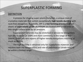
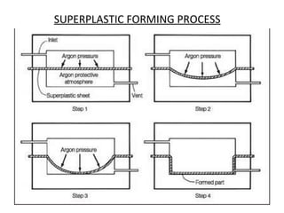
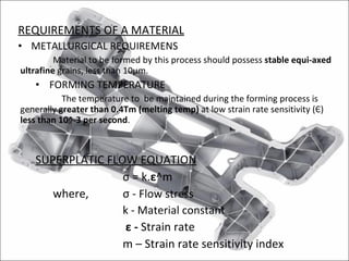
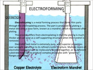
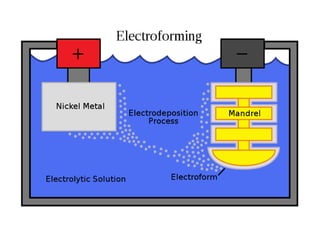
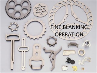
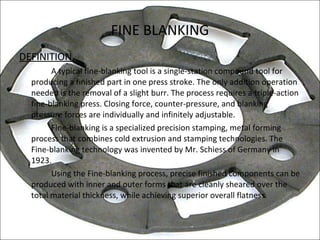
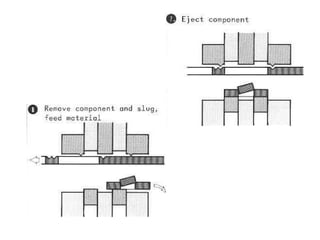
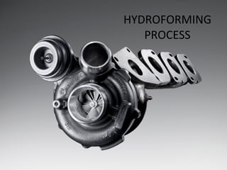
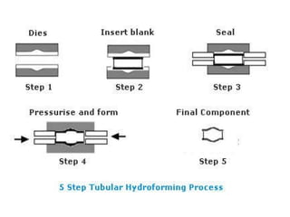
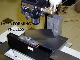
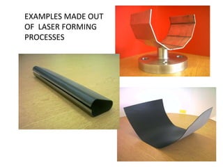
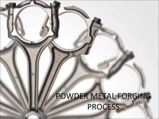
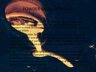
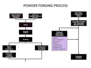
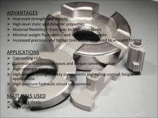
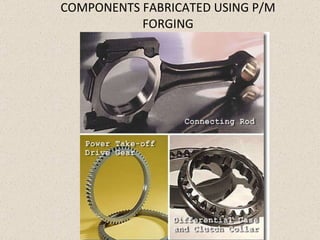
RECENT ADVANCES IN METAL FORMING PROCESSES BY O L K ARAHVINTH
SUPERPLASTIC FORMING
SUPERPLASTIC FORMING DEFINITION A process for shaping super-plastic materials, a unique class of crystalline materials that exhibit exceptionally  high tensile ductility  with neck-free elongation. In specific, SPF is a  hot forming process  in which sheets of  superplastic grade aluminum  are heated and forced onto or into single surface tools by air pressure.  Superplastic materials may be stretched in tension to elongations typically in excess of 200% and more commonly in the range of 400–2000%. There are rare reports of higher tensile elongations reaching as much as 8000%. The high ductility is obtained only for superplastic materials and requires both the temperature and rate of deformation (strain rate) to be within a limited range.
SUPERPLASTIC FORMING PROCESS
REQUIREMENTS OF A MATERIAL METALLURGICAL REQUIREMENS Material to be formed by this process should possess  stable equi-axed ultrafine  grains, less than 10µm. FORMING TEMPERATURE The temperature to  be maintained during the forming process is generally  greater than 0.4Tm (melting temp)  at low strain rate sensitivity ( Є )  less than 10^-3 per second . SUPERPLATIC FLOW EQUATION σ  = k. ε ^m where, σ  -  Flow stress k - Material constant   ε  -  Strain rate m – Strain rate sensitivity index
ADVANTAGES: Complex shapes are easily made. Flexibility in design. Low applied stress for forming HSLA materials. Low capital cost on equipments. Effective material utilization and savings. DISADVANTAGES: Inferior creep resistance Very slow process. APPLICATIONS: Aircraft frames and skins. Window and door frames, floor structures. Propulsion and ducting systems.
ELECTROFORMING PROCESS
ELECTROFORMING DEFINITION Electroforming  is a metal forming process that forms thin parts through the electroplating process. The part is produced by plating a metal skin onto a base form, known as a mandrel, which is removed after plating. This process differs from electroplating in that the plating is much thicker and can exist as a self-supporting structure when the mandrel is removed. Electroformed metal is extremely pure, with superior properties over wrought metal due to its refined crystal structure. Multiple layers of electroformed metal can be molecularly bonded together, or to different substrate materials to produce complex structures with "grown-on" flanges and bosses.
 
STEPS INVOLVED IN THIS PROCESS An electrolytic bath is used to deposit nickel or other electro-platable metal onto a conductive patterned surface, such as glass or stainless steel. Once the plated material has been built up to the desired thickness, the electroformed part is stripped off the master substrate. This process allows high-quality duplication of the master and therefore permits quality production—at low unit costs with high repeatability and excellent process control. The mandrel is made of a non-conductive material it can be covered with a conductive coating. Technically, it is a process of synthesizing a metal object by controlling the electrodeposition of metal passing through an electrolytic solution onto a metal or metalized form. The object being electroformed can be a permanent part of the end product or can be temporary (as in the case of wax), and removed later, leaving only the metal form, the “electroform”.
ADVANTAGES This process is insensitivity to temperature and humidity. Electroformed parts have excellent light transmission when used in optical application, such as encoders, aperture plates, and slits. Electroformed parts have very low mass. Electroformed parts are electrically conductive and unbreakable. DISADVANTAGES Expensive process. Very time consuming; may even require days to obtain he desired thickness. Design limitations exist. Any degradation in the working mandrel may result in flawed output as the surface quality in the mandrel is reflected on to the metal.
FINE BLANKING OPERATION
FINE BLANKING DEFINITION A typical fine-blanking tool is a single-station compound tool for producing a finished part in one press stroke. The only addition operation needed is the removal of a slight burr. The process requires a triple-action fine-blanking press. Closing force, counter-pressure, and blanking pressure forces are individually and infinitely adjustable. Fine-blanking is a specialized precision stamping, metal forming process that combines cold extrusion and stamping technologies. The Fine-blanking technology was invented by Mr. Schiess of Germany in 1923. Using the Fine-blanking process, precise finished components can be produced with inner and outer forms that are cleanly sheared over the total material thickness, while achieving superior overall flatness.
STEPS FOLLOWED IN THIS PROCESS


ADVANTAGES Cleanly sheared edges of fineblanked part vs. extensive die-break in stamped part.  Superior flatness.  Tighter dimensional tolerances. Smaller holes and thinner web sections created in fineblanking often eliminate secondary machining in stamped components.  DISADVANTAGES Cost - if no secondary operations are required to meet specifications, stamping generally will be less expensive.  APPLICATIONS Automotive industry as door locks, gear boxes, reclining seat adjusters, etc. Also used in Electronic and Electrical industry.
HYDROFORMING PROCESS
HYDROFORMING DEFINITION Hydro-forming is a specialized type of die forming that uses a high pressure hydraulic fluid to press room temperature working material into a die. Hydroforming is a relatively new process, popularised by design studies which suggest that automobiles can be made much lighter by using hydroformed components made of steel. Structural strength and stiffness can be improved and the tooling costs reduced because several components can be consolidated into one hydroformed part. Components manufactured by forming can  springback , meaning that the undergo elastic distortion on removing the component from the die. This effect is apparently smaller in hydroformed components.
 
ADVANTAGES Draws material into mould. Part consolidation. Weight reduction through more efficient section design and tailoring of the wall thickness. Improved structural strength and stiffness Reduced scrap. DISADVANTAGES Slow cycle time. Expensive equipment and lack of extensive knowledge base for process and tool design  Requires new welding techniques for assembly. APPLICATIONS Automotive industry. Aircraft structures.
HYDROFORMED COMPONENTS
LASER FORMING PROCESS
LASER FORMING DEFINITION Laser forming (LF) is a highly flexible rapid prototyping and low-volume manufacturing process, which uses laser-induced thermal distortion to shape sheet metal parts without hard tooling or external forces. The laser forming process is of significant value to industries that previously relied on expensive stamping dies and presses for prototype evaluations, relevant industry sectors include aerospace, automotive, and microelectronics. In contrast with conventional forming techniques this method requires no mechanical contact and hence offers many of the advantages of process flexibility associated with other laser manufacturing techniques such as laser cutting and marking. Laser forming can produce metallic, predetermined shapes with minimal distortion.
BASIC LASER FORMING LAYOUT
PRINCIPLE INVOLVED The laser beam is guided across the sheet surface, the path of the laser depends on the desired forming result. In the simplest case it may be a point, in other cases it may be a straight line across the whole part and, for spatially formed parts and extrusions the paths would be very sophisticated radial and tangential lines. There are several distinct mechanisms of laser forming depending on the process set-up, for the Temperature Gradient Mechanism (TGM) above, using a small spot size and fast traverse speed, the thermal expansion of the upper surface of sheet metal would be hindered by the surrounding material, which would result in an upsetting of the heated material. After cooling, the material at the surface is shorter than the material below, giving a bending of the sheet towards the laser beam.
ADVANTAGES No separate external tool is needed for this process. No physical contact. Easy control – laser power, flare diameter and size of the beam. Energy efficient. Variety of applications. Applied for materials that are difficult to form. APPLICATIONS Connecting rods. Automatic transmission races and torque converter races. High-strength gears. High-impact strength safety components and rolling-contact fatigue applications. High-pressure hydraulic circuit components.
EXAMPLES MADE OUT OF  LASER FORMING PROCESSES
POWDER METAL FORGING PROCESS
POWDER METAL FORGING DEFINTION Powder forging (P/F) is used to produce components essentially free of internal porosity.  The associated properties are equivalent to those developed in conventional precision forged products made from billets. Powder forging produces parts that possess mechanical properties equal to wrought materials. Since they’re made using a net-shape technology, P/F parts require only minor secondary machining and offer greater dimensional precision and less flash than conventional precision forgings. In powder forging an as-pressed component is usually heated to a forging temperature significantly below the usual sintering temperature of the material and then forged in a closed die. This produces a fully dense component with the shape of the forging die and appropriate mechanical properties.
POWDER FORGING PROCESS
ADVANTAGES Improved strength and density High-level static and dynamic properties Material flexibility – from low- to high-alloy steels Minimal weight fluctuations and reduced burr waste Increased precision and tighter tolerances compared to wrought forging APPLICATIONS Connecting rods. Automatic transmission races and torque converter races. High-strength gears. High-impact strength safety components and rolling-contact fatigue applications. High-pressure hydraulic circuit components. MATERIALS USED Low alloy steels High alloy steels.
COMPONENTS FABRICATED USING P/M FORGING
THANK YOU…

Recent advances in Metal Forming process

  • 1.
    RECENT ADVANCES INMETAL FORMING PROCESSES BY O L K ARAHVINTH
  • 2.
  • 3.
    SUPERPLASTIC FORMING DEFINITIONA process for shaping super-plastic materials, a unique class of crystalline materials that exhibit exceptionally high tensile ductility with neck-free elongation. In specific, SPF is a hot forming process in which sheets of superplastic grade aluminum are heated and forced onto or into single surface tools by air pressure. Superplastic materials may be stretched in tension to elongations typically in excess of 200% and more commonly in the range of 400–2000%. There are rare reports of higher tensile elongations reaching as much as 8000%. The high ductility is obtained only for superplastic materials and requires both the temperature and rate of deformation (strain rate) to be within a limited range.
  • 4.
  • 5.
    REQUIREMENTS OF AMATERIAL METALLURGICAL REQUIREMENS Material to be formed by this process should possess stable equi-axed ultrafine grains, less than 10µm. FORMING TEMPERATURE The temperature to be maintained during the forming process is generally greater than 0.4Tm (melting temp) at low strain rate sensitivity ( Є ) less than 10^-3 per second . SUPERPLATIC FLOW EQUATION σ = k. ε ^m where, σ - Flow stress k - Material constant ε - Strain rate m – Strain rate sensitivity index
  • 6.
    ADVANTAGES: Complex shapesare easily made. Flexibility in design. Low applied stress for forming HSLA materials. Low capital cost on equipments. Effective material utilization and savings. DISADVANTAGES: Inferior creep resistance Very slow process. APPLICATIONS: Aircraft frames and skins. Window and door frames, floor structures. Propulsion and ducting systems.
  • 7.
  • 8.
    ELECTROFORMING DEFINITION Electroforming is a metal forming process that forms thin parts through the electroplating process. The part is produced by plating a metal skin onto a base form, known as a mandrel, which is removed after plating. This process differs from electroplating in that the plating is much thicker and can exist as a self-supporting structure when the mandrel is removed. Electroformed metal is extremely pure, with superior properties over wrought metal due to its refined crystal structure. Multiple layers of electroformed metal can be molecularly bonded together, or to different substrate materials to produce complex structures with "grown-on" flanges and bosses.
  • 9.
  • 10.
    STEPS INVOLVED INTHIS PROCESS An electrolytic bath is used to deposit nickel or other electro-platable metal onto a conductive patterned surface, such as glass or stainless steel. Once the plated material has been built up to the desired thickness, the electroformed part is stripped off the master substrate. This process allows high-quality duplication of the master and therefore permits quality production—at low unit costs with high repeatability and excellent process control. The mandrel is made of a non-conductive material it can be covered with a conductive coating. Technically, it is a process of synthesizing a metal object by controlling the electrodeposition of metal passing through an electrolytic solution onto a metal or metalized form. The object being electroformed can be a permanent part of the end product or can be temporary (as in the case of wax), and removed later, leaving only the metal form, the “electroform”.
  • 11.
    ADVANTAGES This processis insensitivity to temperature and humidity. Electroformed parts have excellent light transmission when used in optical application, such as encoders, aperture plates, and slits. Electroformed parts have very low mass. Electroformed parts are electrically conductive and unbreakable. DISADVANTAGES Expensive process. Very time consuming; may even require days to obtain he desired thickness. Design limitations exist. Any degradation in the working mandrel may result in flawed output as the surface quality in the mandrel is reflected on to the metal.
  • 12.
  • 13.
    FINE BLANKING DEFINITIONA typical fine-blanking tool is a single-station compound tool for producing a finished part in one press stroke. The only addition operation needed is the removal of a slight burr. The process requires a triple-action fine-blanking press. Closing force, counter-pressure, and blanking pressure forces are individually and infinitely adjustable. Fine-blanking is a specialized precision stamping, metal forming process that combines cold extrusion and stamping technologies. The Fine-blanking technology was invented by Mr. Schiess of Germany in 1923. Using the Fine-blanking process, precise finished components can be produced with inner and outer forms that are cleanly sheared over the total material thickness, while achieving superior overall flatness.
  • 14.
    STEPS FOLLOWED INTHIS PROCESS
  • 15.
  • 16.
  • 17.
  • 18.
    ADVANTAGES Cleanly shearededges of fineblanked part vs. extensive die-break in stamped part. Superior flatness. Tighter dimensional tolerances. Smaller holes and thinner web sections created in fineblanking often eliminate secondary machining in stamped components. DISADVANTAGES Cost - if no secondary operations are required to meet specifications, stamping generally will be less expensive. APPLICATIONS Automotive industry as door locks, gear boxes, reclining seat adjusters, etc. Also used in Electronic and Electrical industry.
  • 19.
  • 20.
    HYDROFORMING DEFINITION Hydro-formingis a specialized type of die forming that uses a high pressure hydraulic fluid to press room temperature working material into a die. Hydroforming is a relatively new process, popularised by design studies which suggest that automobiles can be made much lighter by using hydroformed components made of steel. Structural strength and stiffness can be improved and the tooling costs reduced because several components can be consolidated into one hydroformed part. Components manufactured by forming can springback , meaning that the undergo elastic distortion on removing the component from the die. This effect is apparently smaller in hydroformed components.
  • 21.
  • 22.
    ADVANTAGES Draws materialinto mould. Part consolidation. Weight reduction through more efficient section design and tailoring of the wall thickness. Improved structural strength and stiffness Reduced scrap. DISADVANTAGES Slow cycle time. Expensive equipment and lack of extensive knowledge base for process and tool design Requires new welding techniques for assembly. APPLICATIONS Automotive industry. Aircraft structures.
  • 23.
  • 24.
  • 25.
    LASER FORMING DEFINITIONLaser forming (LF) is a highly flexible rapid prototyping and low-volume manufacturing process, which uses laser-induced thermal distortion to shape sheet metal parts without hard tooling or external forces. The laser forming process is of significant value to industries that previously relied on expensive stamping dies and presses for prototype evaluations, relevant industry sectors include aerospace, automotive, and microelectronics. In contrast with conventional forming techniques this method requires no mechanical contact and hence offers many of the advantages of process flexibility associated with other laser manufacturing techniques such as laser cutting and marking. Laser forming can produce metallic, predetermined shapes with minimal distortion.
  • 26.
  • 27.
    PRINCIPLE INVOLVED Thelaser beam is guided across the sheet surface, the path of the laser depends on the desired forming result. In the simplest case it may be a point, in other cases it may be a straight line across the whole part and, for spatially formed parts and extrusions the paths would be very sophisticated radial and tangential lines. There are several distinct mechanisms of laser forming depending on the process set-up, for the Temperature Gradient Mechanism (TGM) above, using a small spot size and fast traverse speed, the thermal expansion of the upper surface of sheet metal would be hindered by the surrounding material, which would result in an upsetting of the heated material. After cooling, the material at the surface is shorter than the material below, giving a bending of the sheet towards the laser beam.
  • 28.
    ADVANTAGES No separateexternal tool is needed for this process. No physical contact. Easy control – laser power, flare diameter and size of the beam. Energy efficient. Variety of applications. Applied for materials that are difficult to form. APPLICATIONS Connecting rods. Automatic transmission races and torque converter races. High-strength gears. High-impact strength safety components and rolling-contact fatigue applications. High-pressure hydraulic circuit components.
  • 29.
    EXAMPLES MADE OUTOF LASER FORMING PROCESSES
  • 30.
  • 31.
    POWDER METAL FORGINGDEFINTION Powder forging (P/F) is used to produce components essentially free of internal porosity.  The associated properties are equivalent to those developed in conventional precision forged products made from billets. Powder forging produces parts that possess mechanical properties equal to wrought materials. Since they’re made using a net-shape technology, P/F parts require only minor secondary machining and offer greater dimensional precision and less flash than conventional precision forgings. In powder forging an as-pressed component is usually heated to a forging temperature significantly below the usual sintering temperature of the material and then forged in a closed die. This produces a fully dense component with the shape of the forging die and appropriate mechanical properties.
  • 32.
  • 33.
    ADVANTAGES Improved strengthand density High-level static and dynamic properties Material flexibility – from low- to high-alloy steels Minimal weight fluctuations and reduced burr waste Increased precision and tighter tolerances compared to wrought forging APPLICATIONS Connecting rods. Automatic transmission races and torque converter races. High-strength gears. High-impact strength safety components and rolling-contact fatigue applications. High-pressure hydraulic circuit components. MATERIALS USED Low alloy steels High alloy steels.
  • 34.
  • 35.