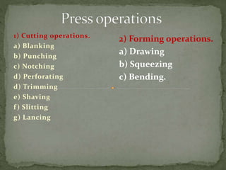
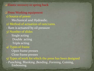
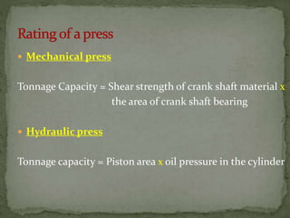
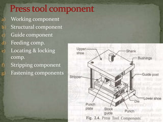
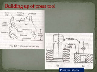
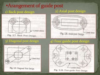
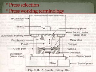
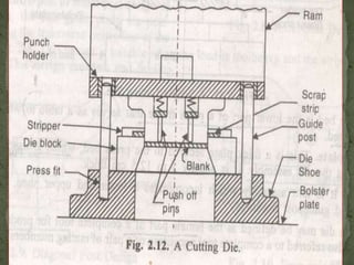
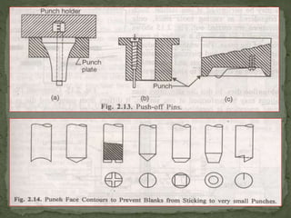
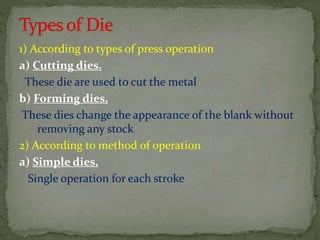
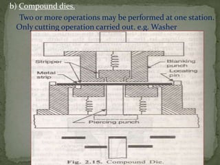
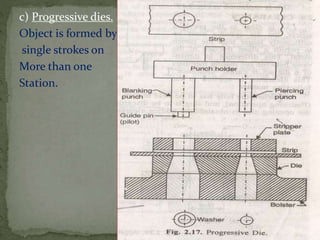
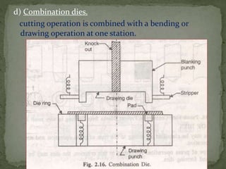
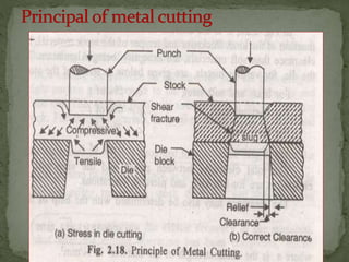
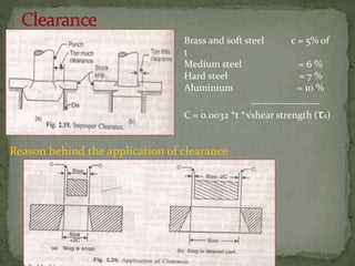
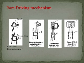
1) Cutting operations.
a) Blanking
b) Punching
c) Notching
d) Perforating
d) Trimming
e) Shaving
f) Slitting
g) Lancing
2) Forming operations.
a) Drawing
b) Squeezing
c) Bending.
Stamping :
The work piece obtained after one or more press
operation is called a metal stamping.
Advantages of metal stamping
1) Small weight
2) High productivity (30000 to 40000 parts per 8 hr.)
3) High efficiency technique
4) Good accuracy
5) Low-Cost production
6) Predictable strength characteristics
7) Low cost material
8) Less labour consuming
 Elastic recovery or spring back
 Press Working equipment
1) Source of power
- Mechanical and Hydraulic.
2) Method of actuation of ram/rams.
- Ram is actuated by oil pressure
3) Number of slides
- Single acting
- Double acting
- Triple acting
4) Types of frame
- Open frame presses
- Close frame presses
5) Types of work for which the press has been designed
- Punching, Blanking ,Bending ,Forming, Coining,
Embossing.
 Mechanical press
Tonnage Capacity = Shear strength of crank shaft material x
the area of crank shaft bearing
 Hydraulic press
Tonnage capacity = Piston area x oil pressure in the cylinder
 Requirement of Press tool design
- Dimensional accuracy and surface finish
- Die and Punch must be strong
- Standard components are used for its
manufacture.
- Scrap in stamping operation must be minimum
a) Working component
b) Structural component
c) Guide component
d) Feeding comp.
e) Locating & locking
comp.
f) Stripping component
g) Fastening components
Press tool shank
1) Back post design 2) Axial post design
3) Diagonal post design 4) Four guide post design
1) According to types of press operation
a) Cutting dies.
These die are used to cut the metal
b) Forming dies.
These dies change the appearance of the blank without
removing any stock
2) According to method of operation
a) Simple dies.
Single operation for each stroke
b) Compound dies.
Two or more operations may be performed at one station.
Only cutting operation carried out. e.g. Washer
c) Progressive dies.
Object is formed by
single strokes on
More than one
Station.
d) Combination dies.
cutting operation is combined with a bending or
drawing operation at one station.
e) Transfer dies.
In transfer dies the already blanks are fed
mechanically from station to station.
f) Multiple dies.
Multiple dies produce two or more work piece
at each stroke of the press.
Brass and soft steel c = 5% of
t
Medium steel = 6 %
Hard steel = 7 %
Aluminium = 10 %
______________
C = 0.0032 *t *√shear strength (τs)
Reason behind the application of clearance
 For blank
Die opening size is made to the correct blank size
and the punch is made smaller an amount equal to
die clearance.
Die opening control the blank size.
 For Punching operation
Punch is made to the correct hole size and the die
opening is made oversize an amount equal to die
clearance.
Punch control the hole size.
Ram Driving mechanism
Crank and
Connecting rod
Crank
Connecting
rod
Pillar
Ram
 cutting forces
Cutting force for
circular blank Fmax = ∏ * D* t * τs.
Rectangular blank = 2(L+b)t * τs.
Energy or work done in press work
E= Fmax * punch travel
=Fmax * K * t.
Where K=percentage of penetration required to cause rupture.
Work done =Area under curve
= (maximum punch force) * (punch travel)
If shear on the cutting tool is zero
Punch travel= (% penetration)*(Material thickness)
Work done = Fmax * K * t -------------(i)
Where, K= % of penetration required to cause the
rupture
If shear is provided on punch or die, then
Punch travel=K*t + Amount of shear in cm = K*t + I
I= Total inclination or shear of punch in cm
Work done = F * (K*t + I) --------------------(ii)
Where, F, is actual force and it will be less the Fmax
Comparing equation (i) & (ii)
I =(Fmax -F) * K* t
F
F=Fmax * K * t
2) Staggering of punch
1) Drop through die
2) Inverted type die
Factors which will influence the stock layout
1)Economy of material
2) Direction of material grains
3) Press used
4) Production required
5) Spacing between blanks
Back or front scrap may be determined by the equation
a= t + 0.015*h
Feed, s= w + b
Number of blanks which can be produced from one
length of stock can be found as,
N= L-b
S
1) Fixed strippers
Plate thickness
t = 1 (w/3 + 16t)
8
2) Spring loaded Strippers
1) Latch stop
2) Automatic stop
Spherical type
B = A
C = 0.25 A
L = A to 2A
E = 0.625 A
Flat type
B = A
C = 0.625 A
L = 0.75 A
E = 0.5 A
Press tool 1
Press tool 1
Press tool 1
Press tool 1
Press tool 1
Press tool 1
Press tool 1

Press tool 1

  • 1.
    1) Cutting operations. a)Blanking b) Punching c) Notching d) Perforating d) Trimming e) Shaving f) Slitting g) Lancing 2) Forming operations. a) Drawing b) Squeezing c) Bending.
  • 2.
    Stamping : The workpiece obtained after one or more press operation is called a metal stamping. Advantages of metal stamping 1) Small weight 2) High productivity (30000 to 40000 parts per 8 hr.) 3) High efficiency technique 4) Good accuracy 5) Low-Cost production 6) Predictable strength characteristics 7) Low cost material 8) Less labour consuming
  • 3.
     Elastic recoveryor spring back  Press Working equipment 1) Source of power - Mechanical and Hydraulic. 2) Method of actuation of ram/rams. - Ram is actuated by oil pressure 3) Number of slides - Single acting - Double acting - Triple acting 4) Types of frame - Open frame presses - Close frame presses 5) Types of work for which the press has been designed - Punching, Blanking ,Bending ,Forming, Coining, Embossing.
  • 4.
     Mechanical press TonnageCapacity = Shear strength of crank shaft material x the area of crank shaft bearing  Hydraulic press Tonnage capacity = Piston area x oil pressure in the cylinder
  • 5.
     Requirement ofPress tool design - Dimensional accuracy and surface finish - Die and Punch must be strong - Standard components are used for its manufacture. - Scrap in stamping operation must be minimum
  • 6.
    a) Working component b)Structural component c) Guide component d) Feeding comp. e) Locating & locking comp. f) Stripping component g) Fastening components
  • 7.
  • 8.
    1) Back postdesign 2) Axial post design 3) Diagonal post design 4) Four guide post design
  • 12.
    1) According totypes of press operation a) Cutting dies. These die are used to cut the metal b) Forming dies. These dies change the appearance of the blank without removing any stock 2) According to method of operation a) Simple dies. Single operation for each stroke
  • 13.
    b) Compound dies. Twoor more operations may be performed at one station. Only cutting operation carried out. e.g. Washer
  • 14.
    c) Progressive dies. Objectis formed by single strokes on More than one Station.
  • 15.
    d) Combination dies. cuttingoperation is combined with a bending or drawing operation at one station.
  • 16.
    e) Transfer dies. Intransfer dies the already blanks are fed mechanically from station to station. f) Multiple dies. Multiple dies produce two or more work piece at each stroke of the press.
  • 18.
    Brass and softsteel c = 5% of t Medium steel = 6 % Hard steel = 7 % Aluminium = 10 % ______________ C = 0.0032 *t *√shear strength (τs) Reason behind the application of clearance
  • 19.
     For blank Dieopening size is made to the correct blank size and the punch is made smaller an amount equal to die clearance. Die opening control the blank size.  For Punching operation Punch is made to the correct hole size and the die opening is made oversize an amount equal to die clearance. Punch control the hole size.
  • 20.
    Ram Driving mechanism Crankand Connecting rod Crank Connecting rod
  • 21.
  • 22.
     cutting forces Cuttingforce for circular blank Fmax = ∏ * D* t * τs. Rectangular blank = 2(L+b)t * τs. Energy or work done in press work E= Fmax * punch travel =Fmax * K * t. Where K=percentage of penetration required to cause rupture.
  • 23.
    Work done =Areaunder curve = (maximum punch force) * (punch travel) If shear on the cutting tool is zero Punch travel= (% penetration)*(Material thickness) Work done = Fmax * K * t -------------(i) Where, K= % of penetration required to cause the rupture If shear is provided on punch or die, then Punch travel=K*t + Amount of shear in cm = K*t + I I= Total inclination or shear of punch in cm Work done = F * (K*t + I) --------------------(ii) Where, F, is actual force and it will be less the Fmax Comparing equation (i) & (ii) I =(Fmax -F) * K* t F F=Fmax * K * t
  • 24.
  • 25.
  • 26.
  • 27.
    Factors which willinfluence the stock layout 1)Economy of material 2) Direction of material grains 3) Press used 4) Production required
  • 28.
    5) Spacing betweenblanks Back or front scrap may be determined by the equation a= t + 0.015*h Feed, s= w + b Number of blanks which can be produced from one length of stock can be found as, N= L-b S
  • 29.
    1) Fixed strippers Platethickness t = 1 (w/3 + 16t) 8
  • 30.
  • 33.
  • 34.
  • 35.
    Spherical type B =A C = 0.25 A L = A to 2A E = 0.625 A Flat type B = A C = 0.625 A L = 0.75 A E = 0.5 A