Download to read offline
![Mohammed Nassraoui et al. Int. Journal of Engineering Research and Applications www.ijera.com
ISSN: 2248-9622, Vol. 5, Issue 8, (Part - 1) August 2015, pp.91-95
www.ijera.com 91 | P a g e
Probabilistic approach to study the hydroformed sheet
Mohammed Nassraoui*
, Bouchaib Radi*
and Abdelghani Saouab**
*
LIMII, F.S.T Settat, BP : 577, Route de Casa, Settat, Morocco
**
LOMC, Université Le Havre, 53 rue Prony, BP 540, France
ABSTRACT
Under the leadership of the Kyoto agreements on reducing emissions of greenhouse gases, the automotive sector
was forced to review its methods and production technologies in order to meet the new environmental standards.
In fuel consumption reduction is an immediate way to reduce the emission of polluting gases. In this paper, the
study of the formability of sheet submitted to the hydroforming process is proposed. The numerical results are
given to validate the proposed approach. To show the influence of uncertainties in the study process, we take
some characteristics of the material as random and the probabilistic approach is done. The finding results are
showing the effectiveness of the proposed approach.
I. INTRODUCTION
Under the leadership of the Kyoto agreements on
reducing emissions of green-house gases, the
automotive sector is seen in the obligation to review
its methods and production technologies in order to
meet the new environmental standards. Deducted
from the fuel consumption is an immediate way to
reduce the emission of polluting gases [1].
Weight reduction needs have actually resulted in
the introduction of new lighter shades in automotive
structures. Thus, aluminum alloys have be-gun to be
integrated into the structural parts of various vehicles.
Besides aluminum, new grades of high-strength steel
have also developed a specific offering mass
resistance ratio better than conventional steels.
Reduce weight is not just about developing new
lighter and more efficient materials but also reducing
the number of elementary parts. Thus reducing the
number of structural parts systematically causes the
reduction of the raw material used, to weld or blank
having only utility as that of the welding process
requirements.
However, the production of complex geometries
in a single piece is often not feasible with the
conventional drawing process. Therefore, the hydro-
forming process has been introduced as an alternative
technology.
All hydroforming process technologies as
diverse and varied, are based on the same principle,
namely the operation of the action of a fluid under
pressure to the shaping of a primary part that can be a
tube, a blank or a double blank (see figure 1).
Figure 1: Hydroforming process
In the formatting process large deformations can
cause irreversible dam-age mechanisms leading to
strain localization before the break. To account for
this phenomenon, several theories have been
proposed to couple damage constitutive models. The
most used approaches can be classified into two
categories: damage formulation micromechanics, and
the continuous damage models. The best-known
examples of each category are the Gurson damage
theory [2], and the mechanics of continuous damage
[3]. The first approach is to describe the degradation
of the material by means of an internal variable
representing the volume fraction of microcavities
formed during charging. We restrict the scope of
uncoupled stresses to temperature or strain rate.
However, modeling takes into consideration the
effects of anisotropy and the large deformation.
The objective of this work is therefore to study
the formability of sheet submitted to the
hydroforming process. For this purpose, the circular
section of sheet steel S250 is hydroformed in a
circular section matrix using a hydroforming machine
manufactured previously. Subsequently, the finished
elements model is designed to simulate the
hydroforming process. The influence of certain
parameters, such as strain hardening, and the
anisotropy of the coefficient of friction, on the
thickness of the sheet in the section is analyzed. Our
RESEARCH ARTICLE OPEN ACCESS](https://image.slidesharecdn.com/q58019195-150813051927-lva1-app6891/75/Probabilistic-approach-to-study-the-hydroformed-sheet-1-2048.jpg)
![Mohammed Nassraoui et al. Int. Journal of Engineering Research and Applications www.ijera.com
ISSN: 2248-9622, Vol. 5, Issue 8, (Part - 1) August 2015, pp.91-95
www.ijera.com 92 | P a g e
job is to analyze the process by a probabilistic
approach taking into account the characteristics of the
material.
II. Description of the hydroforming
process
Hydroforming process is a method which has
several recent innovative advantages over
conventional forming methods. This technique is
very effective to make complex shapes in a single
operation. It is a technique that enables the
production of metal parts, using a high pressure
liquid to force a thin sheet or tube in a mold. The
result can be a continuum that is extremely
lightweight, strong and durable. Manufacturers can
produce custom hydroformed parts on demand and
can make generic parts for sale and mass distribution.
Custom parts costs can depend on the size of the
order and complexity. For the manufacture of
specialized components, costs can be very high,
because technicians may need to spend time on the
development of technical specifications and plans
before creating the mold [4].
A hydroforming technique uses a fluid-filled
bladder. A technician places a flat sheet of metal on a
mold and closing the mold, with the bladder by
applying a pressure on one side. The technician
increases the pressure, and the bladder forces the
metal in the mold. When the technician opens the two
halves, the formed part can be fully withdrawn. High
levels of forms are possible with this method, and the
metal can be very thin for light production
techniques.
Another option is forming the tube. In this
variant, the technician closes a tube within a mold
having a cut somewhere along the length of the tube
form and used to maintain the mold blocks in place.
Then, the high pressure pumps technicians in the
metal tube. The tube expands outwardly to
accommodate the pressure and conforms to the shape
of the mold. The technician can empty the tube and
remove the mold, revealing a full game [5].
The costs of hydroforming may increase with
large, complex molds. Technicians may need to
experiment with the mold and the fluid to get the
right level of pressure, which could require the
manufacture of parts of several tests before moving
on to the final production. For some components,
fluidity and durability are worth the cost of
hydroforming. Sector enterprises also constantly new
techniques in development to reduce costs and
increase reliability [6].
III. Problem statement
The behavior of the sheet is more often discussed
in the context of an elasto-plastic approach for most
forms of sheet forming processes. The elastic-plastic
theory itself has two different approaches to
describing each of them a physical scale behavior:
the first is called phenomenological approach (or
gross) and the second is called microscopic approach
(or micro-macro model). The two approaches are
intended to describe the evolution of the state of
stress and strain in a succession of deformations.
The elasto-plastic behavior is based on a
decomposition of the total apparent deformation in a
reversible elastic part and a plastic part irreversible.
When the elastic portion is small enough, it is
common to adopt an additive decomposition of the
tensor rate deformations:
(1)
and are the strain rate tensor, respectively,
elastic and plastic. The total strain rate tensor is, in
the case of small deformations, the symmetrical part
of the tensor gradient of the velocity field V; which is
written by:
(V)+ grad (v)T
) (2)
The elasticity reflects a reversible
deformation of the material. Most often, it is
considered isotropic linear in the case of cold steel.
In these conditions, the Cauchy stress tensor is
connected to the elastic deformation rate tensor by
Hooke's law:
(3)
I is the identity tensor, and µ are the Lame
coefficients derived from the Poisson's coefficient
and the Young's modulus E by the following
equations:
(4)
And (5)
Therefore the potential state (Helmholtz free
energy) is given by the scalar function of a convex
containing the origin and a resilient plastic part:
(6)
(7)
And (8)
The stress strain relationship is given by the
known relationship as the generalized Hooke's law by
the expression:
(9)
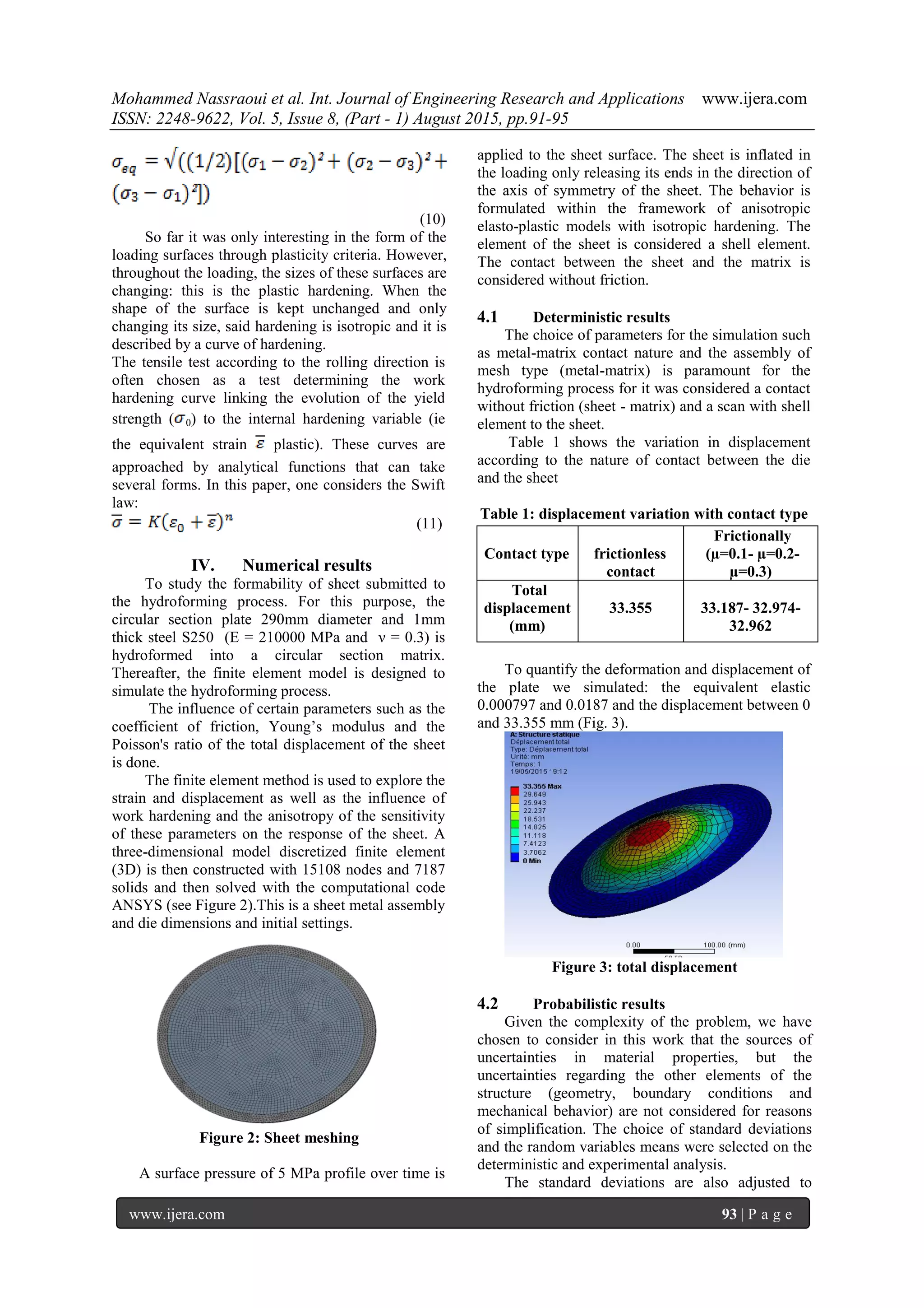
The Von-Mises yield criterion for determining
the plastic yield point of an isotropic metallic
material. The material is supposed to come into
plasticity when its elastic shear energy reaches a
threshold value. For a diagonal tensor of the
constraints, the criterion of Von-Mises can be written
as follows:](https://image.slidesharecdn.com/q58019195-150813051927-lva1-app6891/75/Probabilistic-approach-to-study-the-hydroformed-sheet-2-2048.jpg)
![Mohammed Nassraoui et al. Int. Journal of Engineering Research and Applications www.ijera.com
ISSN: 2248-9622, Vol. 5, Issue 8, (Part - 1) August 2015, pp.91-95
www.ijera.com 95 | P a g e
choice of contact type proposed by ANSYS has had
a good influence on the numerical results just as the
choice of the type of finite elements of the plate.
Our next study is about the reliability analysis of
some hydroforming process and to propose the good
technic to compute the reliability index and deduce
the failure’s probability [7].
REFERENCES:
[1] Gelin, J. C.Labergere, C. Modelling,
optimization and optimal control for
hydroforming process, Proceedings of the
4th international ESAFORM Conference on
Material Forming- Volume 1, Liege,
Belgium (2001) p. 377-380.
[2] J. Lemaitre, A course on damage mechanics.
Springer, Berlin, 1992.
[3] Hashagen, F., Numerical analysis of thin
sheet metal forming and hydroforming with
brick and prismatic finite elements, rapport,
Faculty of Aerospace engineering Delft
University of Technology, July, 1999.
[4] Zhang S.H., Lang L.H., Kang D.C.,
Danckert J., Nielson K.B., Hydromechanical
deep-drawing of aluminium parabolic
workpieces-experiments and numerical
simulation, Machine tools & manufacture ; p
40, 1479-1492, 2000.
[5] Altan,T.; Ahmetoglu, M.; Hydroforming
101 Workshop, Auto Tube Hydroforming
Conference, Westein Southfield, Detroit,
Michigan, May 2-4, 2000.
[6] B. Radi, A. Cherouat, M. Ayadi and A. El
Hami; Materials characterization of an
hydroformed structure. International Journal
Simulation of Multidisciplinary Design
Optimization. vol. 4, p 39-47, 2010.
[7] B. Radi and A. El Hami; Reliability analysis
of the metal forming process. Mathematical
and Computer Modelling, vol 45, p 431-439,
2007](https://image.slidesharecdn.com/q58019195-150813051927-lva1-app6891/75/Probabilistic-approach-to-study-the-hydroformed-sheet-5-2048.jpg)

The document discusses a probabilistic approach to studying the hydroforming process of sheets, particularly in the context of the automotive sector's need to reduce greenhouse gas emissions by improving production technologies and reducing weight. It examines the effectiveness of various materials and their properties under probabilistic models, using finite element methods to analyze the formability and displacement responses of steel sheets during hydroforming. The findings indicate that the choice of material characteristics significantly influences the process, and a potential direction for future research is suggested to enhance the reliability of hydroforming.