Downloaded 695 times
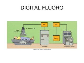
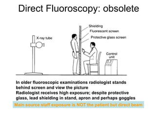


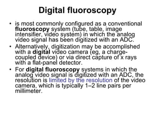
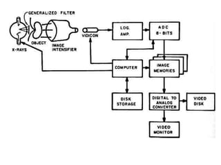
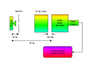

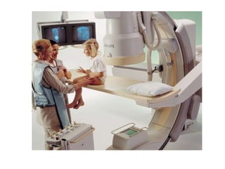

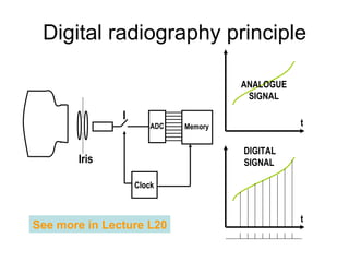

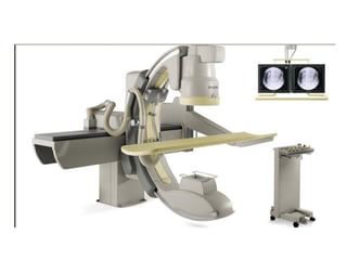
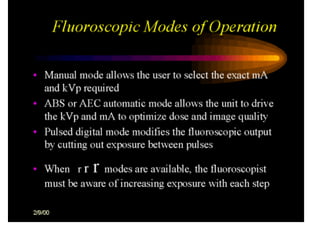
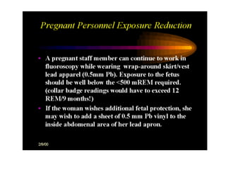
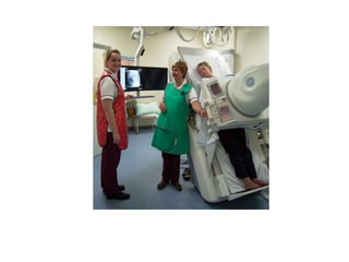

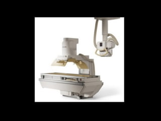


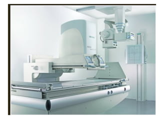

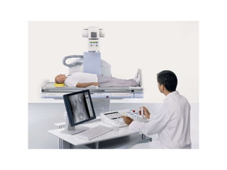

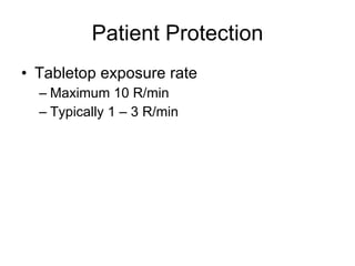

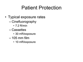
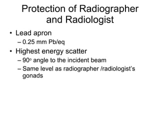
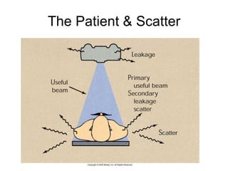


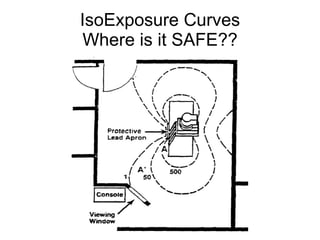
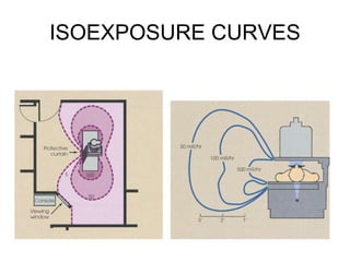
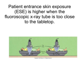

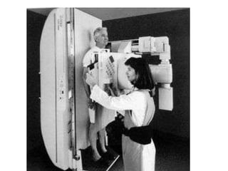
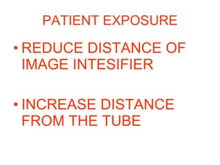


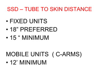
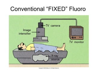
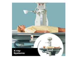
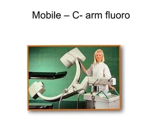


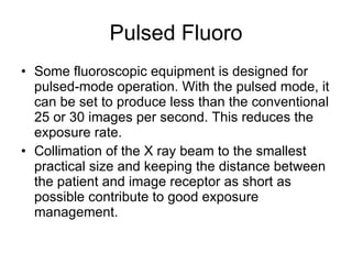
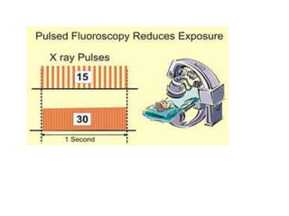

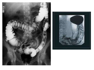

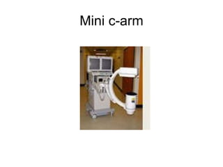
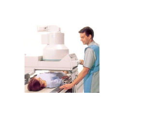
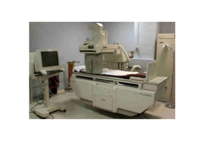
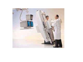
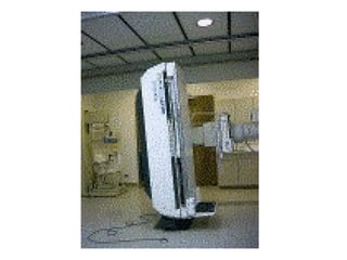


Digital fluoroscopy is most commonly configured as a conventional fluoroscopy system where the analog video signal is converted to digital format via an analog-to-digital converter. Alternatively, digitization can be done with a digital video camera or direct capture of x-rays with a flat panel detector. Digital fluoroscopy systems allow for digital image recording and processing using techniques like frame averaging and edge enhancement. Radiation protection for patients and staff is important for digital fluoroscopy and techniques like collimation, minimum source-to-skin distance, and lead shielding help reduce exposure.