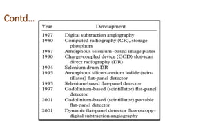
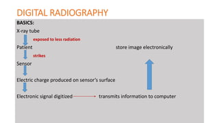
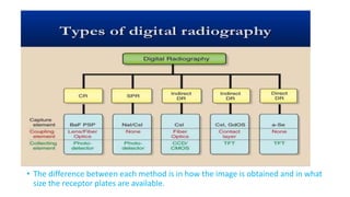
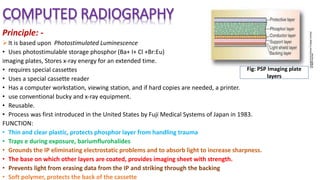
PRESENTER:
RINU MAHARJAN
B.Sc. MIT 2015
BPKIHS,DHARAN
CONTENTS
• Digital Imaging definition
• History
• Formation of digital image
• Advantages
• Digital radiography
 CR
DR
SPR
Digital Fluoroscopy
DSA
DIGITAL IMAGE
• Digital Imaging is defined as any image acquisition process that
produces an electronic image that can be viewed and manipulated
on a computer.
• A digital image consists of a large collection of individual pixels
that are organized in a matrix consisting of rows and columns. Each
pixel is assigned a tonal value (black, white, shades of gray or color),
which is represented in binary code (zeros and ones).
• Digital imaging is integral to current radiology practice, wherein
images are acquired, processed, post-processed, and displayed in
black and white, grayscale, or color, using binary numbers.
• Incorporates computer technology in the capture, display,
enhancement and storage of direct radiographic images.
pixel
Voxel
Historical Development of Digital Imaging
• Term was first used medically in 1970s in CT. first scanner was developed by
Siemens. Early CT scanners required hours to produce a single slice and
reconstruction images took several days to produce.
• MRI became available in the early 1980s.Lauterbur paper in 1973 sparked
companies to research MRI.
• Advancements in fluoroscopy occurred in the 1970s as well.
• Fluoroscopic images could also be stored on a computer.
• Ultrasound and nuclear medicine used screen capture to grab the image and
convert it digitally.
• Eventually, mammography converted to digital format.
Formation of digital image
• Involves several steps, beginning with analog processing.
• Each pixel consists of individual electronic detector, absorbs x-ray,
generates small voltage proportional to the amount of x-ray absorbed
within the detector.
• The voltage fluctuation at each pixel is therefore known as “analogue
signal”
• Conversion of the analog signal into an useful digital image is done
through a process called “Analog to Digital Conversion” (ADC)
• Advances in digital technology have led to a unique
“filmless” imaging system known as Digital Radiography.
• Superior grey scale resolution.
• reduce exposure to radiation
• Image manipulation like contrast enchacement,
measurement, 3-D reconstruction, etc.
• Significantly better dynamic range of digital image
acquisition.
• No loss of quality due to chemical processing time ,
Improved reliability, error free retrieval of images
without loss.
• Storage :a CD ROM can hold number of images.
• Teleradiology
• Environmentally friendly: no processing
chemicals are used or disposed of. Both CCD
sensors and the PSP plates are capable of
being reused for many thousands of
exposures.
• No darkroom
Disadvantages:
 Initial set up costly
 Receptor susceptible to rough handling and
costly to replace.
• Concept began with Albert Jutras in Canada in the 1950s.
• Early PACS system were developed by the military to send images
between Veterans Administration hospitals in the 1980s
• Development was encouraged and supported by the U.S. government
• Early process involved scanning radiographs into the computer and
sending them from computer to computer.
• Images were then stored in PACS.
• Computed and digital radiography followed.
Contd…
DIGITAL RADIOGRAPHY
BASICS:
X-ray tube
exposed to less radiation
Patient store image electronically
strikes
Sensor
Electric charge produced on sensor’s surface
Electronic signal digitized transmits information to computer
• The difference between each method is in how the image is obtained and in what
size the receptor plates are available.
COMPUTED RADIOGRAPHY
Principle: -
It is based upon Photostimulated Luminescence
• Uses photostimulable storage phosphor (Ba+ I+ Cl +Br:Eu)
imaging plates, Stores x-ray energy for an extended time.
• requires special cassettes
• Uses a special cassette reader
• Has a computer workstation, viewing station, and if hard copies are needed, a printer.
• use conventional bucky and x-ray equipment.
• Reusable.
• Process was first introduced in the United States by Fuji Medical Systems of Japan in 1983.
FUNCTION:
• Thin and clear plastic, protects phosphor layer from handling trauma
• Traps e during exposure, bariumflurohalides
• Grounds the IP eliminating electrostatic problems and to absorb light to increase sharpness.
• The base on which other layers are coated, provides imaging sheet with strength.
• Prevents light from erasing data from the IP and striking through the backing
• Soft polymer, protects the back of the cassette
Fig: PSP Imaging plate
layers
Continue…
• The whole readout process for a 14 × 17-inch image plate takes about 30–40 seconds.
Advantages:
a wide dynamic range, which leads to reduced rates of failed x-ray exposure.
Compatible with conventional x-ray equipment
Post processing can be done
Underexposure and overexposure can be manipulated.
are highly mobile, and are easy to use for bedside examinations and immobile patients, making
these systems flexible in routine clinical use.
 if a single image plate shows defects, it can easily be replaced with no need for specialized
equipment or service personnel.
Fig: CR system based on storage-phosphor image plates
DIGITAL RADIOGRAPHY
• Cassetteless system, receptor provides direct digital output
• Uses a flat panel detector, no processor or reader required
• Requires new installation of room
• Images available in < 15 seconds.
• First clinical application was in 1970s in digital subtraction.
• University of Arizon scientists applied the technique.
• Several companies began developing large field detectors.
• DR used CCD technology developed by the military and then used TFT arrays
shortly after and continues to develop in parallel.
Types of Digital Radiography
INDIRECT CAPTURE DR:
Machine absorbs x-rays and converts them to light.
CCD or thin film transistor converts light to electric
signals.
Computer processes electric signals.
Images are viewed on computer monitor.
DIRECT CAPTURE DR:
• Photoconductor absorbs x-rays
• TFT collects signal.
• Electric signal is sent to computer for processing
• Image is viewed on computer screen.
Fig: Digital radiography system
SCAN PROJECTION RADIOGRAPHY:
• Shortly after the introduction of third generation CT, SPR was developed by CT vendors to facilitate patient
positioning.
• The patient is positioned on the CT couch and then is driven through the gantry while the x-ray tube is energized.
• The x-ray tube and the detector array do not rotate but are stationary and the result is a digital radiograph.
COMPONENTS OF S.P.R. SYSTEM:
1. X-Ray Tube.
2. Pre-Patient Collimator.
3. Post-Patient Collimator.
4. Detector Array.
• The x-ray beam is collimated to a fan by prepatient collimators, postpatient image forming x-rays likewise are
collimated to a fan that corresponds to the detector array, a scintillation phosphor usually NaI or CsI used and is
married to a linear array of CCDs through a fiberoptic light path.
• Fan beam of 2-10 mm thickness through an arc of 30-40 degree
• X-ray tube employed must have high heat storage capacity (500 KHU – 1 MHU)
Advantages:
• High scatter rejection
• High image contrast
• Image manipulation.
Disadvantages:
• Scanning time is more,
increasing image blur.
• Poor spatial resolution
• More radiation dose to the
patient.
Digital Fluoroscopy
• Real time dynamic study of internal structures.
Contd….
Image Intensifier Tube:
Electronic device, receive remnant x-ray beam, converts it into light and
increases the light intensity.
Modern II have input field size upto 57 cm in diameter with little image
distortion and the vaccum cases are usually made of metal
Encased in lead housing of 2mm Pb
• Glass envelope maintains tube vaccum to allow control of electron flow
• Input Phosphor: CsI:Na (smaller with greater packing density), energy
convert into burst of visible light photons,
concave screen present results in reduction distortion by keeping the
same distance between all points on the input and output screens.
• Photocathode: Cesium and antimony compounds, respond to stimulation
by light with the emission of electrons, photoemission.
• Electrostatic focusing lens focuses the electrons across the tube from IP
to OP
• Anode is located in the neck of II tube, applied potential is +25 to +35 kv
result in gain of k.e. by the electrons.
• Output Phosphor, ZnCS:Ag, 1”, produce more light photons than the
initial photo electrons.
Video
camera
DSA (Digital Subtraction Angiography)
• The acquisition of digital fluoroscopic images combined with injection of contrast
material and real time subtraction of pre and post contrast images to perform
angiography is referred to as DSA.
Principle:
• The scout film shows the structural details of the skull and the adjacent soft tissue.
• Angiogram film shows exactly the same anatomic details, if the patient does not move,
plus the opacified blood vessels.
• If all the information in the scout film could be subtracted from the angiogram film, only the
opacified vessel pattern would remain visible.
Advantages of Digital Radiography and differences with CR
Disadvantages of DR CR
Time taken
More expensive initial cost Low initial investment
Effective for smaller or low
volume clinics
Cannot be used in portable radiography Use
Not compatible with existing tables Compatible with a wide range
of traditional systems.
Requires protection from dropping or
mishandling and if damaged whole
system will not work.
Replace cassette done
AEC Risk of over and under exposure
Less flexibility Multiple size allow for greater
flexibility
Immediate readout done
Cassette free operation
Good for high volume radiography
Can be used for mammography
Detectors can be re-exposed
immediately
Greater dose efficiency
DIGITAL IMAGING

DIGITAL IMAGING

  • 1.
  • 2.
    CONTENTS • Digital Imagingdefinition • History • Formation of digital image • Advantages • Digital radiography  CR DR SPR Digital Fluoroscopy DSA
  • 3.
    DIGITAL IMAGE • DigitalImaging is defined as any image acquisition process that produces an electronic image that can be viewed and manipulated on a computer. • A digital image consists of a large collection of individual pixels that are organized in a matrix consisting of rows and columns. Each pixel is assigned a tonal value (black, white, shades of gray or color), which is represented in binary code (zeros and ones). • Digital imaging is integral to current radiology practice, wherein images are acquired, processed, post-processed, and displayed in black and white, grayscale, or color, using binary numbers. • Incorporates computer technology in the capture, display, enhancement and storage of direct radiographic images. pixel Voxel
  • 4.
    Historical Development ofDigital Imaging • Term was first used medically in 1970s in CT. first scanner was developed by Siemens. Early CT scanners required hours to produce a single slice and reconstruction images took several days to produce. • MRI became available in the early 1980s.Lauterbur paper in 1973 sparked companies to research MRI. • Advancements in fluoroscopy occurred in the 1970s as well. • Fluoroscopic images could also be stored on a computer. • Ultrasound and nuclear medicine used screen capture to grab the image and convert it digitally. • Eventually, mammography converted to digital format.
  • 5.
    Formation of digitalimage • Involves several steps, beginning with analog processing. • Each pixel consists of individual electronic detector, absorbs x-ray, generates small voltage proportional to the amount of x-ray absorbed within the detector. • The voltage fluctuation at each pixel is therefore known as “analogue signal” • Conversion of the analog signal into an useful digital image is done through a process called “Analog to Digital Conversion” (ADC)
  • 6.
    • Advances indigital technology have led to a unique “filmless” imaging system known as Digital Radiography. • Superior grey scale resolution. • reduce exposure to radiation • Image manipulation like contrast enchacement, measurement, 3-D reconstruction, etc. • Significantly better dynamic range of digital image acquisition. • No loss of quality due to chemical processing time , Improved reliability, error free retrieval of images without loss. • Storage :a CD ROM can hold number of images. • Teleradiology • Environmentally friendly: no processing chemicals are used or disposed of. Both CCD sensors and the PSP plates are capable of being reused for many thousands of exposures. • No darkroom Disadvantages:  Initial set up costly  Receptor susceptible to rough handling and costly to replace.
  • 7.
    • Concept beganwith Albert Jutras in Canada in the 1950s. • Early PACS system were developed by the military to send images between Veterans Administration hospitals in the 1980s • Development was encouraged and supported by the U.S. government • Early process involved scanning radiographs into the computer and sending them from computer to computer. • Images were then stored in PACS. • Computed and digital radiography followed.
  • 8.
  • 9.
    DIGITAL RADIOGRAPHY BASICS: X-ray tube exposedto less radiation Patient store image electronically strikes Sensor Electric charge produced on sensor’s surface Electronic signal digitized transmits information to computer
  • 10.
    • The differencebetween each method is in how the image is obtained and in what size the receptor plates are available.
  • 12.
    COMPUTED RADIOGRAPHY Principle: - Itis based upon Photostimulated Luminescence • Uses photostimulable storage phosphor (Ba+ I+ Cl +Br:Eu) imaging plates, Stores x-ray energy for an extended time. • requires special cassettes • Uses a special cassette reader • Has a computer workstation, viewing station, and if hard copies are needed, a printer. • use conventional bucky and x-ray equipment. • Reusable. • Process was first introduced in the United States by Fuji Medical Systems of Japan in 1983. FUNCTION: • Thin and clear plastic, protects phosphor layer from handling trauma • Traps e during exposure, bariumflurohalides • Grounds the IP eliminating electrostatic problems and to absorb light to increase sharpness. • The base on which other layers are coated, provides imaging sheet with strength. • Prevents light from erasing data from the IP and striking through the backing • Soft polymer, protects the back of the cassette Fig: PSP Imaging plate layers
  • 13.
  • 14.
    • The wholereadout process for a 14 × 17-inch image plate takes about 30–40 seconds. Advantages: a wide dynamic range, which leads to reduced rates of failed x-ray exposure. Compatible with conventional x-ray equipment Post processing can be done Underexposure and overexposure can be manipulated. are highly mobile, and are easy to use for bedside examinations and immobile patients, making these systems flexible in routine clinical use.  if a single image plate shows defects, it can easily be replaced with no need for specialized equipment or service personnel.
  • 15.
    Fig: CR systembased on storage-phosphor image plates
  • 16.
    DIGITAL RADIOGRAPHY • Cassettelesssystem, receptor provides direct digital output • Uses a flat panel detector, no processor or reader required • Requires new installation of room • Images available in < 15 seconds. • First clinical application was in 1970s in digital subtraction. • University of Arizon scientists applied the technique. • Several companies began developing large field detectors. • DR used CCD technology developed by the military and then used TFT arrays shortly after and continues to develop in parallel.
  • 17.
    Types of DigitalRadiography INDIRECT CAPTURE DR: Machine absorbs x-rays and converts them to light. CCD or thin film transistor converts light to electric signals. Computer processes electric signals. Images are viewed on computer monitor. DIRECT CAPTURE DR: • Photoconductor absorbs x-rays • TFT collects signal. • Electric signal is sent to computer for processing • Image is viewed on computer screen.
  • 18.
  • 19.
    SCAN PROJECTION RADIOGRAPHY: •Shortly after the introduction of third generation CT, SPR was developed by CT vendors to facilitate patient positioning. • The patient is positioned on the CT couch and then is driven through the gantry while the x-ray tube is energized. • The x-ray tube and the detector array do not rotate but are stationary and the result is a digital radiograph. COMPONENTS OF S.P.R. SYSTEM: 1. X-Ray Tube. 2. Pre-Patient Collimator. 3. Post-Patient Collimator. 4. Detector Array. • The x-ray beam is collimated to a fan by prepatient collimators, postpatient image forming x-rays likewise are collimated to a fan that corresponds to the detector array, a scintillation phosphor usually NaI or CsI used and is married to a linear array of CCDs through a fiberoptic light path. • Fan beam of 2-10 mm thickness through an arc of 30-40 degree • X-ray tube employed must have high heat storage capacity (500 KHU – 1 MHU)
  • 20.
    Advantages: • High scatterrejection • High image contrast • Image manipulation. Disadvantages: • Scanning time is more, increasing image blur. • Poor spatial resolution • More radiation dose to the patient.
  • 21.
    Digital Fluoroscopy • Realtime dynamic study of internal structures.
  • 22.
    Contd…. Image Intensifier Tube: Electronicdevice, receive remnant x-ray beam, converts it into light and increases the light intensity. Modern II have input field size upto 57 cm in diameter with little image distortion and the vaccum cases are usually made of metal Encased in lead housing of 2mm Pb • Glass envelope maintains tube vaccum to allow control of electron flow • Input Phosphor: CsI:Na (smaller with greater packing density), energy convert into burst of visible light photons, concave screen present results in reduction distortion by keeping the same distance between all points on the input and output screens. • Photocathode: Cesium and antimony compounds, respond to stimulation by light with the emission of electrons, photoemission. • Electrostatic focusing lens focuses the electrons across the tube from IP to OP • Anode is located in the neck of II tube, applied potential is +25 to +35 kv result in gain of k.e. by the electrons. • Output Phosphor, ZnCS:Ag, 1”, produce more light photons than the initial photo electrons.
  • 23.
  • 24.
    DSA (Digital SubtractionAngiography) • The acquisition of digital fluoroscopic images combined with injection of contrast material and real time subtraction of pre and post contrast images to perform angiography is referred to as DSA.
  • 25.
    Principle: • The scoutfilm shows the structural details of the skull and the adjacent soft tissue. • Angiogram film shows exactly the same anatomic details, if the patient does not move, plus the opacified blood vessels. • If all the information in the scout film could be subtracted from the angiogram film, only the opacified vessel pattern would remain visible.
  • 26.
    Advantages of DigitalRadiography and differences with CR Disadvantages of DR CR Time taken More expensive initial cost Low initial investment Effective for smaller or low volume clinics Cannot be used in portable radiography Use Not compatible with existing tables Compatible with a wide range of traditional systems. Requires protection from dropping or mishandling and if damaged whole system will not work. Replace cassette done AEC Risk of over and under exposure Less flexibility Multiple size allow for greater flexibility Immediate readout done Cassette free operation Good for high volume radiography Can be used for mammography Detectors can be re-exposed immediately Greater dose efficiency