What is InterventionalRadiology?
It is a process that intervenes or interferes with the
course of a disease process or other medical condition.
It has more of a therapeutic purpose than diagnostic.
Started in 1960’s.
It allows the angiographer, a specially trained radiologist
to assume an important role in the management and
reduction of disease in many patients.
3.
Advantages:
1. Reduce thelength of patient’s stay in the hospital
2. Helped some patients avoid surgery
3. Lowered medical costs
4.
IR procedures include2 integral parts:
1. Interventional or medical side of the
procedure where the highly skilled
radiologist uses needle, catheters, and
special medical devices ( balloons, coils,
guidewires) to produce an improvement in
the process of the patient.
2. Fluoroscopy and radiography for guiding
and documenting the progress of the steps
taken during the first process.
5.
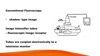
Conventional Fluoroscopy:
• shadow-type image
Image intensifier tubes
– fluoroscopic image receptor
Tubes are coupled electronically to a
television monitor
6.
Digital Fluoroscopy (DF ):
- produces dynamic images obtained with an area x-ray
beam
- multiple monitors
- more complex operating console
- right monitors: modules for entering patient details
8.
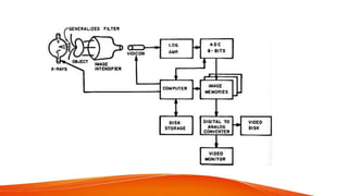
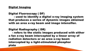
Digital Imaging
Digital Fluoroscopy( DF)
- used to identify a digital x-ray imaging system
that produces a series of dynamic images obtained
with an area x-ray beam and image intensifier.
Digital Radiography ( DR)
- refers to the static images produced with either
a fan x-ray beam intercepted by a linear array of
radiation detectors or an area x-ray beam
intercepted by a light-stimulated phosphor
plate
9.
Advantages of DF:
Thespeed of image acquisition
The post processing image enhancement
One approach developed in 1970 is the use of a narrow
fan beam x-rays that intercepts a linear array of
radiation detectors – referred to as Scanned Projection
Radiography ( SPR )
10.
The signal fromeach detector is computer manipulated
to reconstruct an image.
The second approach was developed in the late 1970’s
by Fuji
It is the computed radiography ( CR) and uses a light
stimulated-phosphor as the image receptor
- Formed from individual image elements
1. HIGH VOLTAGEGENERATOR
- angiointerventional procedures require higher power than may be available
- 3-phase, 12 pulse power capable of at least 100kW with low ripple
13.
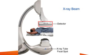
B. X-RAY TUBE
Thex-ray apparatus for an angiointerventional suite is generally more massive, flexible and expensive than that required for conventional radiographic and fluoroscopic imaging.
14.
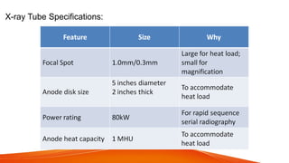
Angiointerventional tube hasa small angle, large-
diameter massive anode disk, and cathode designed
for magnification and serial radiography.
Focal spot: not greater than 0.3mm for spatial
resolution requirements of magnification
radiography of small vessels.
15.
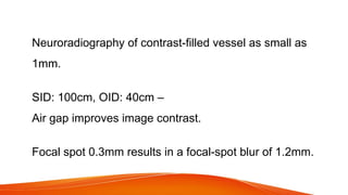
Neuroradiography of contrast-filledvessel as small as
1mm.
SID: 100cm, OID: 40cm –
Air gap improves image contrast.
Focal spot 0.3mm results in a focal-spot blur of 1.2mm.
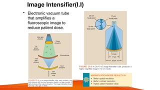
C. IMAGE INTENSIFIER
-it is a complex electronic device that receives the
remnant x-ray beam, converts it into light, and
increases the light intensity
- the tube is usually contained in an evacuated glass
envelope and interacts with the input phosphor
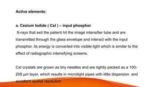
Active elements:
a. CesiumIodide ( CsI ) – input phosphor
X-rays that exit the patient hit the image intensifier tube and are
transmitted through the glass envelope and interact with the input
phosphor, its energy is converted into visible light which is similar to the
effect of radiographic intensifying screens.
CsI crystals are grown as tiny needles and are tightly packed as a 100-
200 µm layer, which results in microlight pipes with little dispersion and
excellent spatial resolution
21.
b. Photocathode
- bondeddirectly to the input phosphor with a thin, transparent,
adhesive layer
- composed of Cesium and antimony compounds that emit
electrons when stimulated by light known as the photoemission
process
- photocathode is a photoemissive surface
22.
Photoemission is electronemission after light stimulation
- the number of electrons emitted by the photocathode is
directly proportional to the intensity of light falling on it
- the number of electrons is proportional to the intensity
of the incident x-rays
23.
Output Phosphor
-Made ofZinc Cadmium Sulfide (ZnCdS), often doped with silver
(Ag).
-This material glows brightly (fluoresces) when struck by
electrons.
24.
The image intensifiertube is approximately 50cm long.
A potential difference of about 25kV is maintained across the
tube between photocathode and anode so that the electrons
will be accelerated to the anode.
The anode is a circular plate with a hole in the middle to allow
the electrons through to the output phosphor
25.
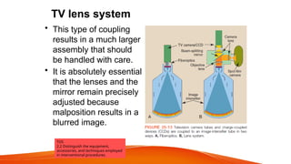
TV lens system
•This type of coupling
results in a much larger
assembly that should
be handled with care.
• It is absolutely essential
that the lenses and the
mirror remain precisely
adjusted because
malposition results in a
blurred image.
TOS
2.2 Distinguish the equipment,
accessories, and techniques employed
in interventional procedures.
26.
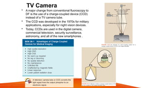
TV Camera
• Amajor change from conventional fluoroscopy to
DF is the use of a charge-coupled device (CCD)
instead of a TV camera tube.
• The CCD was developed in the 1970s for military
applications, especially for night vision devices.
• Today, CCDs are used in the digital camera,
commercial television, security surveillance,
astronomy, and all of the new smartphones .
27.
Electron optics
– engineeringaspects of maintaining proper electron travel
- the electrons emitted over the face of the image-
intensifier tube must be focused just like visible light
28.
Electrostatic focusing lens
-device responsible for focusing the visible light and located
along the length of the image intensifier tube
- the electrons arrive at the output phosphor with high kinetic
energy and contain the image of the input phosphor in minified
form
29.
Zinc cadmium sulfide
–a material for output phosphor
- the electrons in the output phosphor are approximately 50-70 times as
many electrons as needed
Flux gain – the ratio of the number of light photons at the output phosphor to
the number of x-rays at the input phosphor
Flux Gain = Number of output light photons
Number of input x-ray photons
30.
Brightness Gain
– theability of the image intensifier tube to increase the illumination
level of the image
Brightness Gain = Minification gain x Flux gain
The increased illumination is due to the multiplication of the light photons at
the output phosphor compared with the x-rays at the input phosphor and the
image minification from the input to output phosphor
31.
The minification gainis the ratio of the square of the input phosphor to the square of
the diameter of the input phosphor to the square of the diameter of the output
phosphor
Output phosphor size= 2.5cm or 5cm
Input phosphor size= 10-35cm and is used to identify image intensifier tube
32.
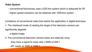
Video System
- conventionalfluoroscopy uses a 525 line system which is adequate for DF
- higher spatial resolution can be obtained with 1000-line system
Limitations of conventional video that restrict the application in digital technique:
1. The interlaced mode of reading the target of the television camera can
significantly degrade
a digital image.
2. The conventional television camera tubes are relatively noisy.
-they have a signal to noise ratio ( SNR) of 200:1
-DF needs an SNR of 1000:1
33.
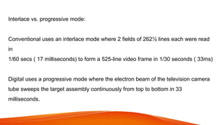
Interlace vs. progressivemode:
Conventional uses an interlace mode where 2 fields of 262½ lines each were read
in
1/60 secs ( 17 milliseconds) to form a 525-line video frame in 1/30 seconds ( 33ms)
Digital uses a progressive mode where the electron beam of the television camera
tube sweeps the target assembly continuously from top to bottom in 33
milliseconds.
34.
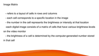
Image Matrix
- refersto a layout of cells in rows and columns
- each cell corresponds to a specific location in the image
- the number in the cell represents the brightness or intensity at that location
-each digital image consists of a matrix of cells that have various brightness levels
on the video monitor
- the brightness of a cell is determined by the computer-generated number stored
in that cell
35.
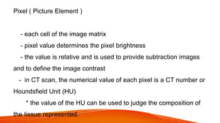
Pixel ( PictureElement )
- each cell of the image matrix
- pixel value determines the pixel brightness
- the value is relative and is used to provide subtraction images
and to define the image contrast
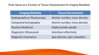
- in CT scan, the numerical value of each pixel is a CT number or
Houndsfield Unit (HU)
* the value of the HU can be used to judge the composition of
the tissue represented.
37.
Pixel Values asa Function of Tissue Characteristics for Imaging Modalities
38.
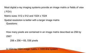
Most digital x-rayimaging systems provide an image matrix or fields of view
( FOV)
Matrix sizes: 512 x 512 and 1024 x 1024
Spatial resolution is better with a larger image matrix
Questions:
How many pixels are contained in an image matrix described as 256 by
256?
256 x 256 = 65, 536 pixels
A 1024 by 1024 image matrix = 1000-line system
39.
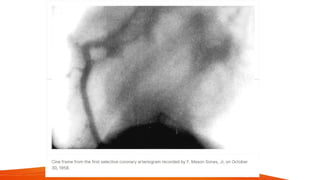
BRIEF HISTORY
1930’s –IR procedures started, with the use of needles
and contrast to highlight an artery.
1960’s – Mason Jones pioneered transbrachial selective
coronary angiography
1960’s – transfemoral angiography entering an artery in the
thigh of selective visceral heart and head arteries was
developed.
- Melvin Judkins introduced coronary angiography
- Charles Dotter introduced visceral angiography
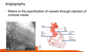
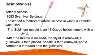
Basic principles
Arterial Access
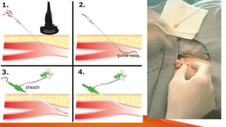
1953Sven Ivar Seldinger
- described a method of arterial access in which a catheter
was used.
- The Seldinger needle is an 18 Gauge hollow needle with a
stylet.
-After the needle is inserted, the stylet is removed, a
guidewire is then placed, needle is then removed, and a
catheter is threaded onto the guidewire.
44.
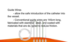
Guide Wires
- allowthe safe introduction of the catheter into
the vessel.
- Conventional guide wires are 145cm long,
fabricated with stainless steel, and coated with
materials that are designed to reduce friction.
45.
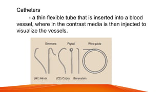
Catheters
- a thinflexible tube that is inserted into a blood
vessel, where in the contrast media is then injected to
visualize the vessels.
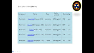
Contrast Media:
- diagnosticagents that are instilled into body
orifices or injected into the vascular system, joints and
ducts to enhance subject contrast in anatomic areas
where there is low subject contrast
51.
Contrast Media Properties:
•- able to show organ better
• - physiologically:
• no permanent alteration of organ
• non-toxic
• can be eliminated/excreted
Vascular interventional radiologytechniques to treat a disease
that is endovascular (inside blood vessels) and has become an
alternative to vascular surgery for some conditions such
as abdominal aortic aneurysm and peripheral artery disease
58.
Seldinger Technique
The Seldingertechnique, also known as Seldinger wire technique, is a medical
procedure to obtain safe access to blood vessels and other hollow organs.
It is named after Dr. Sven-Ivar Seldinger (1921-1998), a Swedish radiologist who
introduced the procedure in 1953.
60.
Peripheral artery disease(PAD)
Most commonly a result of atherosclerosis,
occlusion of normal blood flow in the upper
and lower extremities may result in pain,
skin ulcers, or gangrene.
Stenting, angioplasty, and
mechanical atherectomy are available
interventional treatments. For example, carotid
stenting is used for the treatment of carotid
artery stenosis
61.
Deep vein thrombosis(DVT)
The formation of a thrombus, or blood
clot, in the deep leg veins may lead to
swelling, discoloration, and pain. DVTs
can result in post-thrombotic
syndrome and pulmonary embolism.
62.
Pulmonary embolism
A potentiallylife-threatening occlusion of the arteries
supplying the lungs with blood clots, manifesting in
shortness of breath, fatigue, palpitations, and
fainting.
Catheter-directed thrombolysis may be performed
for this condition, where a catheter is inserted into
the leg, and threaded up to the lung.
63.
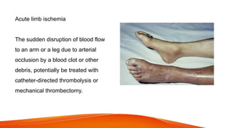
Acute limb ischemia
Thesudden disruption of blood flow
to an arm or a leg due to arterial
occlusion by a blood clot or other
debris, potentially be treated with
catheter-directed thrombolysis or
mechanical thrombectomy.
64.
Acute mesenteric ischemia
Amedical emergency resulting from
interruption of the blood supply to the
abdominal organs due to blockage of
the mesenteric arteries or veins by
thrombus, embolus, or aortic dissection.
Treatment varies by etiology of the ischemia,
but may include thrombolysis, stenting,
or angioplasty.
65.
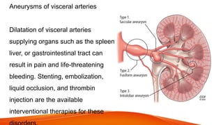
Aneurysms of visceralarteries
Dilatation of visceral arteries
supplying organs such as the spleen,
liver, or gastrointestinal tract can
result in pain and life-threatening
bleeding. Stenting, embolization,
liquid occlusion, and thrombin
injection are the available
interventional therapies for these
Thoracic aortic aneurysms(TAA) and Aortic dissection
Aneurysms, or dilatations, of the thoracic (chest cavity)
aorta, may be caused by atherosclerosis, syphilis,
trauma, or multiple other conditions. Aortic
dissections are tears in the thoracic aorta resulting
from trauma or weakening of the aortic vessel walls
from conditions such as hypertension, atherosclerosis,
and congenital conditions such as Marfan syndrome.
Interventional treatments for TAAs and aortic
dissections utilize stent-grafts, sometimes in
combination with surgery, to prevent blood flow from
enlarging the diseased area or rupturing the aorta.
Editor's Notes
#40 Thrombolysis, Angioplasty, Embolization, Vascular Stents and Biopsy are interventional therapeutic procedures, conducted in and through the vessels.
#45 H1 – head hunter tip, Vincent Hinck, used in both femoral and brachiocephalic approach.
Simmons –used for approach sharply angled vessels and was designed for cerebral angio
C2 or cobra – used for introduction into the celiac, renal and mesenteric arteries.
Pigtail catheters – has a side hole, this can help reduce the possibility of whiplash.