SlideShare a Scribd company logo
1 of 22
COMPUTED RADIOGRAPHY (CR) - AN
OVERVIEW AND EVALUATION OF PIPE
WALL THICKNESS BASED ON CONTRAST
MEASUREMENT
C H YADHUKRISHNA (213118008)
ILLYAS M K (213118010)
MUHAMED MUSTHAFA PULIKKAL (213118015)
INTRODUCTION
ļ¶Computed radiography (CR), also commonly known as Photostimulable
phosphor (PSP) imaging.
ļ¶It employs reusable imaging plates and associated hardware and software to
acquire and to display digital projection radiographs.
ļ¶It is cassette based system like analog film and is more commonly considered to
be a bridge between classical radiography and digital radiography
ļ¶CR is used almost exactly like conventional Imaging plate in a cassette which
must be processed in CR reader after X-ray exposure for conversion to digital
images.
CR system consists of
ļ¶Image plate (photostimulable phosphor) PSP
ļ¶X ray or gamma ray source
ļ¶Image reader/digitizer/scanner
ļ¶Photomultiplier tube (PMT), ADC (analoge to digital converter)
ļ¶Computer console or workstation, software, monitors, and a printer.
Image reader can be
ļ¶Single-plate readers (each cassette is loaded manually and read separately)
ļ¶Multiple-plate readers (multiple platesā€”up to 10ā€”can be stacked and
loaded automatically)
HISTORY
ļ¶Cassette-based computed radiography (CR) systems have continued to
evolve in parallel with integrated, instant readout digital radiography
(DR) systems.
ļ¶The fundamental innovations in the development of CR was by Kodak
(luckey in 1975) who conceived the storage of an X ray image in a
phosphor screen.
ļ¶It required significant technical steps and conceptualization of the
application by Fuji (kotera et al 1980) to produce the first medical X ray
images Fuji, the main developer of CR in the eighties, used BarFBR:šøš‘ˆ2+
phosphor and a cassette-based approach.
PRINCIPLE OF OPERATION
ļ¶In computed radiography, the imaging plates are inserted in a radiographic
tableā€™s cassette holder and are exposed to X-rays or gamma rays.
ļ¶The energy of the incoming radiation is stored in a special phosphor layer,
electrons in the phosphor plate are excited into a higher energy state,
forming a latent image.
ļ¶Then a specialized machine known as a scanner is then used to read out the
latent image from the plate by stimulating it with a very finely focused laser
beam.
ļ¶During which the trapped electrons absorb the laser energy and they emit
blue light with intensity proportional to the amount of radiation received
during the exposure as they return to their ground state.
ļ¶The light is collected by a light guide and transmitted to a highly sensitive
analog device known as a photomultiplier tube (PMT) and converted to a
digital signal using an analog-to-digital converter (ADC).
ļ¶The generated digital X-ray image can then be digitally stored and viewed
on a computer monitor and evaluated.
ļ¶ After an imaging plate is read, it is erased by a high-intensity light source
that removes residual radiation and can immediately be re-used.
ļ¶Imaging plates can typically be used up to 1000 times or more depending
on the application.
LIMITATIONS OF CONVENTIONAL RADIOGRAPHY
ļ¶Films cannot tolerate a wide range in radiation exposure (OD - log E curve)
ļ¶One has to choose between good contrast and good latitude
ļ¶Image cannot be adjusted once taken
ļ¶Require space for dark room and film/chemicals storage..
ļ¶Price of films and chemicals is constantly going up (4-10% per year)
ļ¶Need several exposures to show different tissues (bone vs soft tissue)
ļ¶Image developing time is more (manual about 60 minutes)
STEPS INVOVLVED
ļ¶X ray image received on phosphor plate subjecting to X ray exposure
ļ¶After the image has been captured on an image plate by a standard x-ray system, the plate is taken
to an image-plate reader to extract the image.
ļ¶The cassette is loaded (manually or automatically) into the reader.
ļ¶Image extracted from phosphor plate by laser (Raw image)
ļ¶Raw image processed for quality improvement
ļ¶The digital image is then produced in 30-120 seconds and downloaded to an image-processing
system, usually a computer workstation, for display and manipulation.
ļ¶Digital image can be either printed burned on CD, or sent to PACS(Picture Archiving and
Communication System)
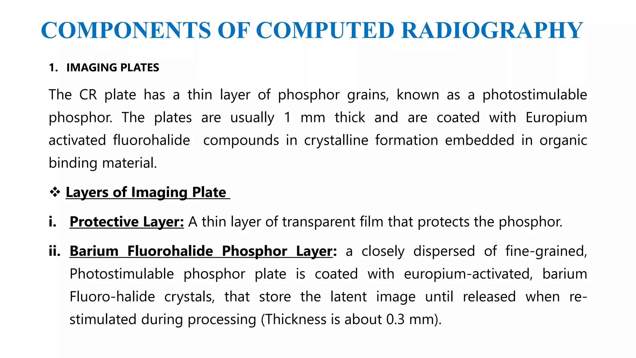
COMPONENTS OF COMPUTED RADIOGRAPHY
1. IMAGING PLATES
The CR plate has a thin layer of phosphor grains, known as a photostimulable
phosphor. The plates are usually 1 mm thick and are coated with Europium
activated fluorohalide compounds in crystalline formation embedded in organic
binding material.
ļ¶ Layers of Imaging Plate
i. Protective Layer: A thin layer of transparent film that protects the phosphor.
ii. Barium Fluorohalide Phosphor Layer: a closely dispersed of fine-grained,
Photostimulable phosphor plate is coated with europium-activated, barium
Fluoro-halide crystals, that store the latent image until released when re-
stimulated during processing (Thickness is about 0.3 mm).
iii. Light reflective Layer: This layer increases the intensity of light being
emitted from the crystals by reflecting it back toward the reader, instead of
it being absorbed.
iv. Conductive Layer: This is a light absorbing layer, made up of conductive
needle-like crystals that absorb any unreflected light as well as any
electrostatic charges.
v. Polyester Support Layer: Made from a polyester material, this layer gives
structural rigidity and a base for the coating of all of the other layers.
Polyester is used because of its excellent stabilities well as its durability and
flexibility.
vi. Light Shielding Layer: This is a carbon particle layer that prevents the light
from leaking from the rear of the imaging plate.
vii.Backing Layer: This is a protective layer made from a soft polymer that
prevents scratching when the plates are stacked during the manufacturing
process.
PROTECTIVE LAYER
BARIUM FLUOROHALIDE PHOPHOR LAYER
REFLETIVE LAYER
CONDUCTIVE LAYER
POLYSTER BASE SUPPORT LAYER
LIGHT SHIELDING LAYER
BACKING LAYER
X-RAY EXPOSURE
ā€¢ When the X-ray is absorbed by the material, absorbed energy excites the
europium atoms, causing ionization of Eu atom.
ā€¢ The electrons are raised to higher energy state in the conduction band.
Where electrons travel freely until they are trapped in a so called F-centre
in a metastable state with an energy level slightly below that of conduction
band but higher than that of the valence band.
ā€¢ The number of trapped electrons per unit area is proportional to intensity
X-rays incident at each location. These trapped electrons constitute the
latent image.
ā€¢ Due to the thermal motion the trapped electrons will slowly be liberated
from the traps, and so at room temperature the image should, however, be
readable up to 8 hours after exposure
IMAGE SCANNING
ļ¶Plate is scanned by the laser causing the emission of blue light from the plate which is then
detected by the photomultiplier. Plate is erased with light (not laser) and returned to the cassette
PHENOMENON OF LASER LIGHT
ļ¶The cassette is placed in the reader where the Image Plate is extracted and raster scanned
with a highly focused and intense laser light of low energy (~2 eV).
ļ¶Laser light is absorbed at the F-center (Farbzentren center) and, thus, stimulates the
trapped electrons up to conduction band where they are free to move to Europium atom
thereby leaving high energy conduction band to lower energy valence band.
ļ¶When these electrons become reabsorbed by trivalent Europium, trivalent Europium is
transferred back into divalent Europium atom. This involves the liberation of high energy
(~3 eV) and this is done by emission of green light. Since, there is a larger energy
difference between conduction band, valence band and F- center, the green light emitted
has a higher energy than the laser light needed to stimulate the trapped electrons.
ļ¶The difference in wavelength between the two light is critical for the detection of emitted light.
Incident x-rays form an ā€œelectronā€ latent image in a metastable ā€œFā€ center site that can be stimulated
with a low energy laser beam (~2.0 eV), producing the desired luminescent signals (~3.0 eV).
PHOTOMULTIPLIER TUBE
ā€¢ A photomultiplier tube (PMT) useful for light detection of very weak signals, is a
photo emissive device in which the absorption of a photon results in the emission of
an electron.
ā€¢ These detectors work by amplifying the electrons generated by a photocathode
exposed to a photon flux.
ERASING PROCESS
ā€¢ Residual latent image information is erased by using an intense light
(consisting of wavelengths that remove electrons in traps without
stimulating further electron trapping), and the image plate is reinserted into
the cassette for reuse.
ā€¢ Exposure to a bright fluorescent light removes the remaining information in
10-15 sec.
ā€¢ Ghosting - if the residual latent image remained so it should be removed by
flooding with intense white light.
ADVANTAGES
ā€¢ CR technology can be considered as the digital replacement of conventional X-ray
film.
ā€¢ Post-processing, manipulation & storage of images is easy.
ā€¢ Repeat examinations are reduced due to wide exposure latitude.
ā€¢ Image Plate is reusable.
ā€¢ Ability to produce consistent high quality images.
ā€¢ Ability to deliver images quickly to those who need to make critical decisions.
ā€¢ Decreased time to acquire images thereby increasing patient throughput in
medical diagnosis.
ā€¢ Increased Radiologist reading capacity and the ability to have instant
comparison images along with previous reports.
ā€¢ Ability to print on paper or make CD media instead of film, economically
profitable.
ā€¢ Increased savings: no film, chemicals, dark room and storage room
required
ā€¢ Computer processing of raw image brightness, contrast, sharpness
enhancement, zooming, measurementsā€¦
ā€¢ Reduction in exposure and processing time
ā€¢ Software based evaluation and reporting
ā€¢ Digital magnification allows better detail viewing
ā€¢ Special analysis tools: e.g. for automated wall thickness measurement
ā€¢ Global data exchange via a local network and/or the Internet
DISADVANTAGES
ā€¢ Initial cost
ā€¢ Additional cost (Service and maintenance)
ā€¢ Plate is sensitive to fogging: use grid, need to be erased daily
ā€¢ Dose-creep: since, exposure latitude is wide, high exposure technique
is used which increases the patient dose which is called dose-creep.

More Related Content

What's hot

Digital fluoro
Digital fluoroDigital fluoro
Digital fluoroRad Tech
Ā 
Emergency radiography
Emergency radiography Emergency radiography
Emergency radiography milan timilsina
Ā 
Radiographic Intensifying Screen
Radiographic Intensifying ScreenRadiographic Intensifying Screen
Radiographic Intensifying ScreenTarique Ajij
Ā 
X ray tube, cassette and screens
X ray tube, cassette and screensX ray tube, cassette and screens
X ray tube, cassette and screensTarun Goyal
Ā 
The x ray tube
The x ray tubeThe x ray tube
The x ray tubeairwave12
Ā 
X ray tube
X ray tubeX ray tube
X ray tubeRad Tech
Ā 
Intensifying screens & films
Intensifying screens & filmsIntensifying screens & films
Intensifying screens & filmsVishwanath R S
Ā 
MACRORADIOGRAPHY.pptx
MACRORADIOGRAPHY.pptxMACRORADIOGRAPHY.pptx
MACRORADIOGRAPHY.pptxThejaTej6
Ā 
Exposure factors2
Exposure factors2Exposure factors2
Exposure factors2mr_koky
Ā 
Beam restricted device and filter used in x ray
Beam restricted device and filter used in x rayBeam restricted device and filter used in x ray
Beam restricted device and filter used in x raySushilPattar
Ā 
Intensifying screen avinesh shrestha
Intensifying screen avinesh shresthaIntensifying screen avinesh shrestha
Intensifying screen avinesh shresthaAvinesh Shrestha
Ā 
Magnification(macro and micro radiography), distortion
Magnification(macro and micro radiography), distortionMagnification(macro and micro radiography), distortion
Magnification(macro and micro radiography), distortionparthajyotidas11
Ā 
Faults in x ray tube and its care
Faults in x ray tube and its careFaults in x ray tube and its care
Faults in x ray tube and its careSaruGosain
Ā 
image intensifier.pptx
image intensifier.pptximage intensifier.pptx
image intensifier.pptxGajananWattamwar1
Ā 
tomography tomography - Presentation Transcript 1. PRINCIPLE OFTOMOGRAPHY...
tomography tomography - Presentation Transcript     1. PRINCIPLE OFTOMOGRAPHY...tomography tomography - Presentation Transcript     1. PRINCIPLE OFTOMOGRAPHY...
tomography tomography - Presentation Transcript 1. PRINCIPLE OFTOMOGRAPHY...Prem Murti
Ā 
Fluroscopy
Fluroscopy Fluroscopy
Fluroscopy Rakesh Ca
Ā 
Image formation of Radiology from Radiation
Image formation of Radiology from RadiationImage formation of Radiology from Radiation
Image formation of Radiology from RadiationSelf
Ā 

What's hot (20)

Digital fluoro
Digital fluoroDigital fluoro
Digital fluoro
Ā 
Emergency radiography
Emergency radiography Emergency radiography
Emergency radiography
Ā 
Radiographic Intensifying Screen
Radiographic Intensifying ScreenRadiographic Intensifying Screen
Radiographic Intensifying Screen
Ā 
X ray tube, cassette and screens
X ray tube, cassette and screensX ray tube, cassette and screens
X ray tube, cassette and screens
Ā 
The x ray tube
The x ray tubeThe x ray tube
The x ray tube
Ā 
X ray tube
X ray tubeX ray tube
X ray tube
Ā 
Screen Film Radiography
Screen Film RadiographyScreen Film Radiography
Screen Film Radiography
Ā 
Intensifying screens & films
Intensifying screens & filmsIntensifying screens & films
Intensifying screens & films
Ā 
MACRORADIOGRAPHY.pptx
MACRORADIOGRAPHY.pptxMACRORADIOGRAPHY.pptx
MACRORADIOGRAPHY.pptx
Ā 
Exposure factors2
Exposure factors2Exposure factors2
Exposure factors2
Ā 
Beam restricted device and filter used in x ray
Beam restricted device and filter used in x rayBeam restricted device and filter used in x ray
Beam restricted device and filter used in x ray
Ā 
Intensifying screen avinesh shrestha
Intensifying screen avinesh shresthaIntensifying screen avinesh shrestha
Intensifying screen avinesh shrestha
Ā 
X ray generators
X ray generatorsX ray generators
X ray generators
Ā 
Magnification(macro and micro radiography), distortion
Magnification(macro and micro radiography), distortionMagnification(macro and micro radiography), distortion
Magnification(macro and micro radiography), distortion
Ā 
Faults in x ray tube and its care
Faults in x ray tube and its careFaults in x ray tube and its care
Faults in x ray tube and its care
Ā 
image intensifier.pptx
image intensifier.pptximage intensifier.pptx
image intensifier.pptx
Ā 
tomography tomography - Presentation Transcript 1. PRINCIPLE OFTOMOGRAPHY...
tomography tomography - Presentation Transcript     1. PRINCIPLE OFTOMOGRAPHY...tomography tomography - Presentation Transcript     1. PRINCIPLE OFTOMOGRAPHY...
tomography tomography - Presentation Transcript 1. PRINCIPLE OFTOMOGRAPHY...
Ā 
Fluroscopy
Fluroscopy Fluroscopy
Fluroscopy
Ā 
X-RAY TUBE (ANODE)
X-RAY TUBE (ANODE)X-RAY TUBE (ANODE)
X-RAY TUBE (ANODE)
Ā 
Image formation of Radiology from Radiation
Image formation of Radiology from RadiationImage formation of Radiology from Radiation
Image formation of Radiology from Radiation
Ā 

Similar to Computed radiography

CR (Computed Radiography) System
CR (Computed Radiography) SystemCR (Computed Radiography) System
CR (Computed Radiography) SystemJNDRSHD
Ā 
Digital radiography.. an update
Digital radiography.. an updateDigital radiography.. an update
Digital radiography.. an updateShivam Batra
Ā 
X ray machines - conventional and digital
X ray machines - conventional and digitalX ray machines - conventional and digital
X ray machines - conventional and digitalUrfeya Mirza
Ā 
Digital radiography/cosmetic dentistry courses
Digital radiography/cosmetic dentistry coursesDigital radiography/cosmetic dentistry courses
Digital radiography/cosmetic dentistry coursesIndian dental academy
Ā 
CR, DR and recent advances
CR, DR and recent advancesCR, DR and recent advances
CR, DR and recent advancesVishal Sankpal
Ā 
RDT-112-PRELIM-LESSON-1.docx
RDT-112-PRELIM-LESSON-1.docxRDT-112-PRELIM-LESSON-1.docx
RDT-112-PRELIM-LESSON-1.docxJianSoliman2
Ā 
COMPUTED RADIOGRAPHY BY SEHRISH
COMPUTED RADIOGRAPHY BY SEHRISHCOMPUTED RADIOGRAPHY BY SEHRISH
COMPUTED RADIOGRAPHY BY SEHRISHSEHRISH97
Ā 
Different types of imaging devices and principles.pptx
Different types of imaging devices and principles.pptxDifferent types of imaging devices and principles.pptx
Different types of imaging devices and principles.pptxAayushiPaul1
Ā 
nasif radiology
nasif radiologynasif radiology
nasif radiologyMohamed Gad
Ā 
Intro to radiography 1_2(NDT)
Intro to radiography 1_2(NDT)Intro to radiography 1_2(NDT)
Intro to radiography 1_2(NDT)Ravi Shekhar
Ā 
Digital Radiography
Digital RadiographyDigital Radiography
Digital RadiographyUpakar Paudel
Ā 
Medical x ray image sensors
Medical x ray image sensorsMedical x ray image sensors
Medical x ray image sensorsIslam Kotb Ismail
Ā 
Orthodontic radiograph..
Orthodontic radiograph.. Orthodontic radiograph..
Orthodontic radiograph.. nehal albelasy
Ā 
Night vision glasses
Night vision glassesNight vision glasses
Night vision glassesWinay Choudhary
Ā 
Computed radiography AND ITS ADVANTAGES
Computed radiography AND ITS ADVANTAGESComputed radiography AND ITS ADVANTAGES
Computed radiography AND ITS ADVANTAGESFirdousDar4
Ā 
Xri fin
Xri finXri fin
Xri finMUBOSScz
Ā 

Similar to Computed radiography (20)

CR (Computed Radiography) System
CR (Computed Radiography) SystemCR (Computed Radiography) System
CR (Computed Radiography) System
Ā 
Digital radiography.. an update
Digital radiography.. an updateDigital radiography.. an update
Digital radiography.. an update
Ā 
X ray machines - conventional and digital
X ray machines - conventional and digitalX ray machines - conventional and digital
X ray machines - conventional and digital
Ā 
Digital radiography/cosmetic dentistry courses
Digital radiography/cosmetic dentistry coursesDigital radiography/cosmetic dentistry courses
Digital radiography/cosmetic dentistry courses
Ā 
CR, DR and recent advances
CR, DR and recent advancesCR, DR and recent advances
CR, DR and recent advances
Ā 
RDT-112-PRELIM-LESSON-1.docx
RDT-112-PRELIM-LESSON-1.docxRDT-112-PRELIM-LESSON-1.docx
RDT-112-PRELIM-LESSON-1.docx
Ā 
COMPUTED RADIOGRAPHY BY SEHRISH
COMPUTED RADIOGRAPHY BY SEHRISHCOMPUTED RADIOGRAPHY BY SEHRISH
COMPUTED RADIOGRAPHY BY SEHRISH
Ā 
Flouroscopy JP.pptx
Flouroscopy JP.pptxFlouroscopy JP.pptx
Flouroscopy JP.pptx
Ā 
Cr system ABHISHEK
Cr system ABHISHEKCr system ABHISHEK
Cr system ABHISHEK
Ā 
Different types of imaging devices and principles.pptx
Different types of imaging devices and principles.pptxDifferent types of imaging devices and principles.pptx
Different types of imaging devices and principles.pptx
Ā 
nasif radiology
nasif radiologynasif radiology
nasif radiology
Ā 
Intro to radiography 1_2(NDT)
Intro to radiography 1_2(NDT)Intro to radiography 1_2(NDT)
Intro to radiography 1_2(NDT)
Ā 
cr srms1.pptx
cr srms1.pptxcr srms1.pptx
cr srms1.pptx
Ā 
Digital Radiography
Digital RadiographyDigital Radiography
Digital Radiography
Ā 
Radiography
RadiographyRadiography
Radiography
Ā 
Medical x ray image sensors
Medical x ray image sensorsMedical x ray image sensors
Medical x ray image sensors
Ā 
Orthodontic radiograph..
Orthodontic radiograph.. Orthodontic radiograph..
Orthodontic radiograph..
Ā 
Night vision glasses
Night vision glassesNight vision glasses
Night vision glasses
Ā 
Computed radiography AND ITS ADVANTAGES
Computed radiography AND ITS ADVANTAGESComputed radiography AND ITS ADVANTAGES
Computed radiography AND ITS ADVANTAGES
Ā 
Xri fin
Xri finXri fin
Xri fin
Ā 

Recently uploaded

BASLIQ CURRENT LOOKBOOK LOOKBOOK(1) (1).pdf
BASLIQ CURRENT LOOKBOOK  LOOKBOOK(1) (1).pdfBASLIQ CURRENT LOOKBOOK  LOOKBOOK(1) (1).pdf
BASLIQ CURRENT LOOKBOOK LOOKBOOK(1) (1).pdfSoniaTolstoy
Ā 
Software Engineering Methodologies (overview)
Software Engineering Methodologies (overview)Software Engineering Methodologies (overview)
Software Engineering Methodologies (overview)eniolaolutunde
Ā 
Presiding Officer Training module 2024 lok sabha elections
Presiding Officer Training module 2024 lok sabha electionsPresiding Officer Training module 2024 lok sabha elections
Presiding Officer Training module 2024 lok sabha electionsanshu789521
Ā 
Paris 2024 Olympic Geographies - an activity
Paris 2024 Olympic Geographies - an activityParis 2024 Olympic Geographies - an activity
Paris 2024 Olympic Geographies - an activityGeoBlogs
Ā 
A Critique of the Proposed National Education Policy Reform
A Critique of the Proposed National Education Policy ReformA Critique of the Proposed National Education Policy Reform
A Critique of the Proposed National Education Policy ReformChameera Dedduwage
Ā 
microwave assisted reaction. General introduction
microwave assisted reaction. General introductionmicrowave assisted reaction. General introduction
microwave assisted reaction. General introductionMaksud Ahmed
Ā 
Sanyam Choudhary Chemistry practical.pdf
Sanyam Choudhary Chemistry practical.pdfSanyam Choudhary Chemistry practical.pdf
Sanyam Choudhary Chemistry practical.pdfsanyamsingh5019
Ā 
Concept of Vouching. B.Com(Hons) /B.Compdf
Concept of Vouching. B.Com(Hons) /B.CompdfConcept of Vouching. B.Com(Hons) /B.Compdf
Concept of Vouching. B.Com(Hons) /B.CompdfUmakantAnnand
Ā 
Presentation by Andreas Schleicher Tackling the School Absenteeism Crisis 30 ...
Presentation by Andreas Schleicher Tackling the School Absenteeism Crisis 30 ...Presentation by Andreas Schleicher Tackling the School Absenteeism Crisis 30 ...
Presentation by Andreas Schleicher Tackling the School Absenteeism Crisis 30 ...EduSkills OECD
Ā 
Class 11 Legal Studies Ch-1 Concept of State .pdf
Class 11 Legal Studies Ch-1 Concept of State .pdfClass 11 Legal Studies Ch-1 Concept of State .pdf
Class 11 Legal Studies Ch-1 Concept of State .pdfakmcokerachita
Ā 
Alper Gobel In Media Res Media Component
Alper Gobel In Media Res Media ComponentAlper Gobel In Media Res Media Component
Alper Gobel In Media Res Media ComponentInMediaRes1
Ā 
18-04-UA_REPORT_MEDIALITERAŠ”Y_INDEX-DM_23-1-final-eng.pdf
18-04-UA_REPORT_MEDIALITERAŠ”Y_INDEX-DM_23-1-final-eng.pdf18-04-UA_REPORT_MEDIALITERAŠ”Y_INDEX-DM_23-1-final-eng.pdf
18-04-UA_REPORT_MEDIALITERAŠ”Y_INDEX-DM_23-1-final-eng.pdfssuser54595a
Ā 
Accessible design: Minimum effort, maximum impact
Accessible design: Minimum effort, maximum impactAccessible design: Minimum effort, maximum impact
Accessible design: Minimum effort, maximum impactdawncurless
Ā 
Crayon Activity Handout For the Crayon A
Crayon Activity Handout For the Crayon ACrayon Activity Handout For the Crayon A
Crayon Activity Handout For the Crayon AUnboundStockton
Ā 
How to Make a Pirate ship Primary Education.pptx
How to Make a Pirate ship Primary Education.pptxHow to Make a Pirate ship Primary Education.pptx
How to Make a Pirate ship Primary Education.pptxmanuelaromero2013
Ā 
Hybridoma Technology ( Production , Purification , and Application )
Hybridoma Technology  ( Production , Purification , and Application  ) Hybridoma Technology  ( Production , Purification , and Application  )
Hybridoma Technology ( Production , Purification , and Application ) Sakshi Ghasle
Ā 
SOCIAL AND HISTORICAL CONTEXT - LFTVD.pptx
SOCIAL AND HISTORICAL CONTEXT - LFTVD.pptxSOCIAL AND HISTORICAL CONTEXT - LFTVD.pptx
SOCIAL AND HISTORICAL CONTEXT - LFTVD.pptxiammrhaywood
Ā 

Recently uploaded (20)

BASLIQ CURRENT LOOKBOOK LOOKBOOK(1) (1).pdf
BASLIQ CURRENT LOOKBOOK  LOOKBOOK(1) (1).pdfBASLIQ CURRENT LOOKBOOK  LOOKBOOK(1) (1).pdf
BASLIQ CURRENT LOOKBOOK LOOKBOOK(1) (1).pdf
Ā 
Model Call Girl in Bikash Puri Delhi reach out to us at šŸ”9953056974šŸ”
Model Call Girl in Bikash Puri  Delhi reach out to us at šŸ”9953056974šŸ”Model Call Girl in Bikash Puri  Delhi reach out to us at šŸ”9953056974šŸ”
Model Call Girl in Bikash Puri Delhi reach out to us at šŸ”9953056974šŸ”
Ā 
Software Engineering Methodologies (overview)
Software Engineering Methodologies (overview)Software Engineering Methodologies (overview)
Software Engineering Methodologies (overview)
Ā 
Presiding Officer Training module 2024 lok sabha elections
Presiding Officer Training module 2024 lok sabha electionsPresiding Officer Training module 2024 lok sabha elections
Presiding Officer Training module 2024 lok sabha elections
Ā 
Paris 2024 Olympic Geographies - an activity
Paris 2024 Olympic Geographies - an activityParis 2024 Olympic Geographies - an activity
Paris 2024 Olympic Geographies - an activity
Ā 
A Critique of the Proposed National Education Policy Reform
A Critique of the Proposed National Education Policy ReformA Critique of the Proposed National Education Policy Reform
A Critique of the Proposed National Education Policy Reform
Ā 
microwave assisted reaction. General introduction
microwave assisted reaction. General introductionmicrowave assisted reaction. General introduction
microwave assisted reaction. General introduction
Ā 
Sanyam Choudhary Chemistry practical.pdf
Sanyam Choudhary Chemistry practical.pdfSanyam Choudhary Chemistry practical.pdf
Sanyam Choudhary Chemistry practical.pdf
Ā 
Concept of Vouching. B.Com(Hons) /B.Compdf
Concept of Vouching. B.Com(Hons) /B.CompdfConcept of Vouching. B.Com(Hons) /B.Compdf
Concept of Vouching. B.Com(Hons) /B.Compdf
Ā 
Presentation by Andreas Schleicher Tackling the School Absenteeism Crisis 30 ...
Presentation by Andreas Schleicher Tackling the School Absenteeism Crisis 30 ...Presentation by Andreas Schleicher Tackling the School Absenteeism Crisis 30 ...
Presentation by Andreas Schleicher Tackling the School Absenteeism Crisis 30 ...
Ā 
TataKelola dan KamSiber Kecerdasan Buatan v022.pdf
TataKelola dan KamSiber Kecerdasan Buatan v022.pdfTataKelola dan KamSiber Kecerdasan Buatan v022.pdf
TataKelola dan KamSiber Kecerdasan Buatan v022.pdf
Ā 
Class 11 Legal Studies Ch-1 Concept of State .pdf
Class 11 Legal Studies Ch-1 Concept of State .pdfClass 11 Legal Studies Ch-1 Concept of State .pdf
Class 11 Legal Studies Ch-1 Concept of State .pdf
Ā 
Alper Gobel In Media Res Media Component
Alper Gobel In Media Res Media ComponentAlper Gobel In Media Res Media Component
Alper Gobel In Media Res Media Component
Ā 
18-04-UA_REPORT_MEDIALITERAŠ”Y_INDEX-DM_23-1-final-eng.pdf
18-04-UA_REPORT_MEDIALITERAŠ”Y_INDEX-DM_23-1-final-eng.pdf18-04-UA_REPORT_MEDIALITERAŠ”Y_INDEX-DM_23-1-final-eng.pdf
18-04-UA_REPORT_MEDIALITERAŠ”Y_INDEX-DM_23-1-final-eng.pdf
Ā 
Accessible design: Minimum effort, maximum impact
Accessible design: Minimum effort, maximum impactAccessible design: Minimum effort, maximum impact
Accessible design: Minimum effort, maximum impact
Ā 
Crayon Activity Handout For the Crayon A
Crayon Activity Handout For the Crayon ACrayon Activity Handout For the Crayon A
Crayon Activity Handout For the Crayon A
Ā 
CĆ³digo Creativo y Arte de Software | Unidad 1
CĆ³digo Creativo y Arte de Software | Unidad 1CĆ³digo Creativo y Arte de Software | Unidad 1
CĆ³digo Creativo y Arte de Software | Unidad 1
Ā 
How to Make a Pirate ship Primary Education.pptx
How to Make a Pirate ship Primary Education.pptxHow to Make a Pirate ship Primary Education.pptx
How to Make a Pirate ship Primary Education.pptx
Ā 
Hybridoma Technology ( Production , Purification , and Application )
Hybridoma Technology  ( Production , Purification , and Application  ) Hybridoma Technology  ( Production , Purification , and Application  )
Hybridoma Technology ( Production , Purification , and Application )
Ā 
SOCIAL AND HISTORICAL CONTEXT - LFTVD.pptx
SOCIAL AND HISTORICAL CONTEXT - LFTVD.pptxSOCIAL AND HISTORICAL CONTEXT - LFTVD.pptx
SOCIAL AND HISTORICAL CONTEXT - LFTVD.pptx
Ā 

Computed radiography

  • 1. COMPUTED RADIOGRAPHY (CR) - AN OVERVIEW AND EVALUATION OF PIPE WALL THICKNESS BASED ON CONTRAST MEASUREMENT C H YADHUKRISHNA (213118008) ILLYAS M K (213118010) MUHAMED MUSTHAFA PULIKKAL (213118015)
  • 2. INTRODUCTION ļ¶Computed radiography (CR), also commonly known as Photostimulable phosphor (PSP) imaging. ļ¶It employs reusable imaging plates and associated hardware and software to acquire and to display digital projection radiographs. ļ¶It is cassette based system like analog film and is more commonly considered to be a bridge between classical radiography and digital radiography ļ¶CR is used almost exactly like conventional Imaging plate in a cassette which must be processed in CR reader after X-ray exposure for conversion to digital images.
  • 3. CR system consists of ļ¶Image plate (photostimulable phosphor) PSP ļ¶X ray or gamma ray source ļ¶Image reader/digitizer/scanner ļ¶Photomultiplier tube (PMT), ADC (analoge to digital converter) ļ¶Computer console or workstation, software, monitors, and a printer. Image reader can be ļ¶Single-plate readers (each cassette is loaded manually and read separately) ļ¶Multiple-plate readers (multiple platesā€”up to 10ā€”can be stacked and loaded automatically)
  • 4. HISTORY ļ¶Cassette-based computed radiography (CR) systems have continued to evolve in parallel with integrated, instant readout digital radiography (DR) systems. ļ¶The fundamental innovations in the development of CR was by Kodak (luckey in 1975) who conceived the storage of an X ray image in a phosphor screen. ļ¶It required significant technical steps and conceptualization of the application by Fuji (kotera et al 1980) to produce the first medical X ray images Fuji, the main developer of CR in the eighties, used BarFBR:šøš‘ˆ2+ phosphor and a cassette-based approach.
  • 5. PRINCIPLE OF OPERATION ļ¶In computed radiography, the imaging plates are inserted in a radiographic tableā€™s cassette holder and are exposed to X-rays or gamma rays. ļ¶The energy of the incoming radiation is stored in a special phosphor layer, electrons in the phosphor plate are excited into a higher energy state, forming a latent image. ļ¶Then a specialized machine known as a scanner is then used to read out the latent image from the plate by stimulating it with a very finely focused laser beam. ļ¶During which the trapped electrons absorb the laser energy and they emit blue light with intensity proportional to the amount of radiation received during the exposure as they return to their ground state.
  • 6. ļ¶The light is collected by a light guide and transmitted to a highly sensitive analog device known as a photomultiplier tube (PMT) and converted to a digital signal using an analog-to-digital converter (ADC). ļ¶The generated digital X-ray image can then be digitally stored and viewed on a computer monitor and evaluated. ļ¶ After an imaging plate is read, it is erased by a high-intensity light source that removes residual radiation and can immediately be re-used. ļ¶Imaging plates can typically be used up to 1000 times or more depending on the application.
  • 7. LIMITATIONS OF CONVENTIONAL RADIOGRAPHY ļ¶Films cannot tolerate a wide range in radiation exposure (OD - log E curve) ļ¶One has to choose between good contrast and good latitude ļ¶Image cannot be adjusted once taken ļ¶Require space for dark room and film/chemicals storage.. ļ¶Price of films and chemicals is constantly going up (4-10% per year) ļ¶Need several exposures to show different tissues (bone vs soft tissue) ļ¶Image developing time is more (manual about 60 minutes)
  • 8. STEPS INVOVLVED ļ¶X ray image received on phosphor plate subjecting to X ray exposure ļ¶After the image has been captured on an image plate by a standard x-ray system, the plate is taken to an image-plate reader to extract the image. ļ¶The cassette is loaded (manually or automatically) into the reader. ļ¶Image extracted from phosphor plate by laser (Raw image) ļ¶Raw image processed for quality improvement ļ¶The digital image is then produced in 30-120 seconds and downloaded to an image-processing system, usually a computer workstation, for display and manipulation. ļ¶Digital image can be either printed burned on CD, or sent to PACS(Picture Archiving and Communication System)
  • 9.
  • 10. COMPONENTS OF COMPUTED RADIOGRAPHY 1. IMAGING PLATES The CR plate has a thin layer of phosphor grains, known as a photostimulable phosphor. The plates are usually 1 mm thick and are coated with Europium activated fluorohalide compounds in crystalline formation embedded in organic binding material. ļ¶ Layers of Imaging Plate i. Protective Layer: A thin layer of transparent film that protects the phosphor. ii. Barium Fluorohalide Phosphor Layer: a closely dispersed of fine-grained, Photostimulable phosphor plate is coated with europium-activated, barium Fluoro-halide crystals, that store the latent image until released when re- stimulated during processing (Thickness is about 0.3 mm).
  • 11. iii. Light reflective Layer: This layer increases the intensity of light being emitted from the crystals by reflecting it back toward the reader, instead of it being absorbed. iv. Conductive Layer: This is a light absorbing layer, made up of conductive needle-like crystals that absorb any unreflected light as well as any electrostatic charges. v. Polyester Support Layer: Made from a polyester material, this layer gives structural rigidity and a base for the coating of all of the other layers. Polyester is used because of its excellent stabilities well as its durability and flexibility. vi. Light Shielding Layer: This is a carbon particle layer that prevents the light from leaking from the rear of the imaging plate. vii.Backing Layer: This is a protective layer made from a soft polymer that prevents scratching when the plates are stacked during the manufacturing process.
  • 12. PROTECTIVE LAYER BARIUM FLUOROHALIDE PHOPHOR LAYER REFLETIVE LAYER CONDUCTIVE LAYER POLYSTER BASE SUPPORT LAYER LIGHT SHIELDING LAYER BACKING LAYER
  • 13. X-RAY EXPOSURE ā€¢ When the X-ray is absorbed by the material, absorbed energy excites the europium atoms, causing ionization of Eu atom. ā€¢ The electrons are raised to higher energy state in the conduction band. Where electrons travel freely until they are trapped in a so called F-centre in a metastable state with an energy level slightly below that of conduction band but higher than that of the valence band. ā€¢ The number of trapped electrons per unit area is proportional to intensity X-rays incident at each location. These trapped electrons constitute the latent image. ā€¢ Due to the thermal motion the trapped electrons will slowly be liberated from the traps, and so at room temperature the image should, however, be readable up to 8 hours after exposure
  • 14. IMAGE SCANNING ļ¶Plate is scanned by the laser causing the emission of blue light from the plate which is then detected by the photomultiplier. Plate is erased with light (not laser) and returned to the cassette
  • 15. PHENOMENON OF LASER LIGHT ļ¶The cassette is placed in the reader where the Image Plate is extracted and raster scanned with a highly focused and intense laser light of low energy (~2 eV). ļ¶Laser light is absorbed at the F-center (Farbzentren center) and, thus, stimulates the trapped electrons up to conduction band where they are free to move to Europium atom thereby leaving high energy conduction band to lower energy valence band. ļ¶When these electrons become reabsorbed by trivalent Europium, trivalent Europium is transferred back into divalent Europium atom. This involves the liberation of high energy (~3 eV) and this is done by emission of green light. Since, there is a larger energy difference between conduction band, valence band and F- center, the green light emitted has a higher energy than the laser light needed to stimulate the trapped electrons.
  • 16. ļ¶The difference in wavelength between the two light is critical for the detection of emitted light. Incident x-rays form an ā€œelectronā€ latent image in a metastable ā€œFā€ center site that can be stimulated with a low energy laser beam (~2.0 eV), producing the desired luminescent signals (~3.0 eV).
  • 17. PHOTOMULTIPLIER TUBE ā€¢ A photomultiplier tube (PMT) useful for light detection of very weak signals, is a photo emissive device in which the absorption of a photon results in the emission of an electron. ā€¢ These detectors work by amplifying the electrons generated by a photocathode exposed to a photon flux.
  • 18. ERASING PROCESS ā€¢ Residual latent image information is erased by using an intense light (consisting of wavelengths that remove electrons in traps without stimulating further electron trapping), and the image plate is reinserted into the cassette for reuse. ā€¢ Exposure to a bright fluorescent light removes the remaining information in 10-15 sec. ā€¢ Ghosting - if the residual latent image remained so it should be removed by flooding with intense white light.
  • 19.
  • 20. ADVANTAGES ā€¢ CR technology can be considered as the digital replacement of conventional X-ray film. ā€¢ Post-processing, manipulation & storage of images is easy. ā€¢ Repeat examinations are reduced due to wide exposure latitude. ā€¢ Image Plate is reusable. ā€¢ Ability to produce consistent high quality images. ā€¢ Ability to deliver images quickly to those who need to make critical decisions.
  • 21. ā€¢ Decreased time to acquire images thereby increasing patient throughput in medical diagnosis. ā€¢ Increased Radiologist reading capacity and the ability to have instant comparison images along with previous reports. ā€¢ Ability to print on paper or make CD media instead of film, economically profitable. ā€¢ Increased savings: no film, chemicals, dark room and storage room required ā€¢ Computer processing of raw image brightness, contrast, sharpness enhancement, zooming, measurementsā€¦ ā€¢ Reduction in exposure and processing time ā€¢ Software based evaluation and reporting ā€¢ Digital magnification allows better detail viewing ā€¢ Special analysis tools: e.g. for automated wall thickness measurement ā€¢ Global data exchange via a local network and/or the Internet
  • 22. DISADVANTAGES ā€¢ Initial cost ā€¢ Additional cost (Service and maintenance) ā€¢ Plate is sensitive to fogging: use grid, need to be erased daily ā€¢ Dose-creep: since, exposure latitude is wide, high exposure technique is used which increases the patient dose which is called dose-creep.