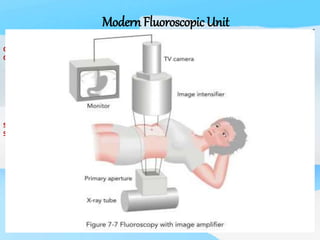
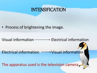
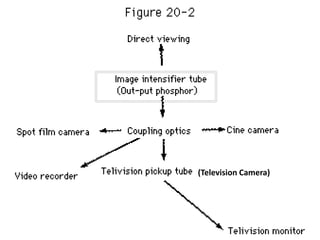
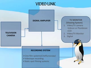
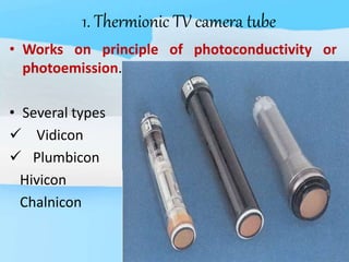
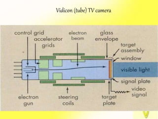
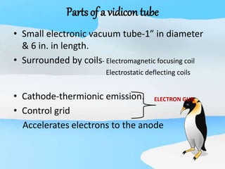
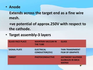
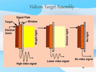
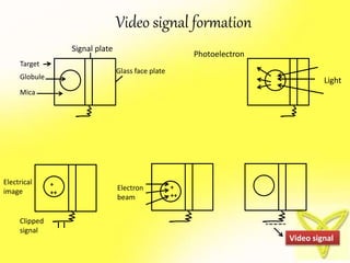
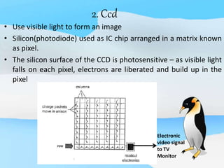
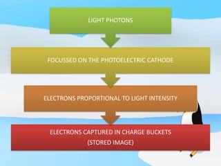
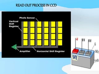
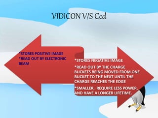
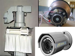
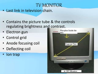
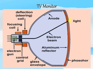
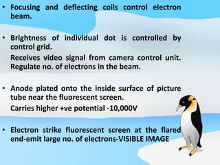
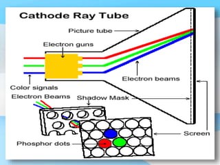
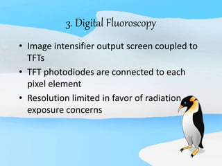
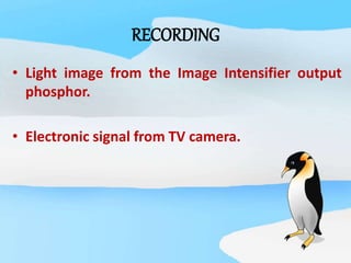
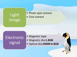
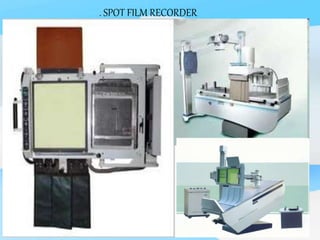
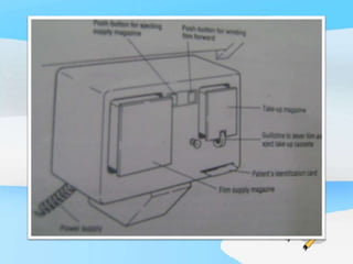
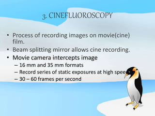
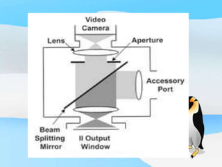
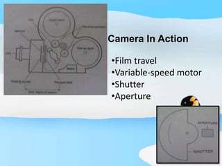
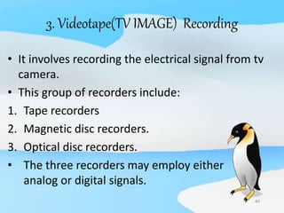
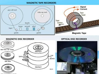
VIEWING AND RECORDING
OF THE
INTENSIFIED IMAGE
Shashi Bhushan
B Sc MIT (2nd
Year)
Modern FluoroscopicUnit
CINE OR PHOTOSPOT
CAMERA
SPOTFILM CASSETTE
SLOT
IMAGE INTENSIFIER
VIDEO MONITOR
PATIENT COUCH
UNDER COUCH X RAY TUBE
CONTROL KNOBS
INTENSIFICATION
• Process of brightening the image.
Visual information Electrical information
Electrical information Visual information
The apparatus used is the television camera
(Television Camera)
TELEVISION
CAMERA
SIGNAL AMPLIFIER TV MONITOR
(Viewing System)
1. Video/TV camera
-Vidicon or Plumbicon
-CCD
2. Video/TV Monitor
3. Digital
RECORDING SYSTEM
Cine film systems(Cinefluroscopy)
Videotape recording
Static spot filming systems
VIDEO LINK
TELEVISION CAMERA COUPLING
a) FIBRE OPTIC COUPLING b) OPTICAL LENS COUPLING
Because of the limitations of the mirror optic
viewing system, a more practical and efficient
viewing system was employed.
1.Afford viewing by multiple persons.
2.Monitors may be located in remote locations
other than the radiographic room.
3.Image brightness and contrast can be
manipulated.
4.Images may be stored on different medium
for reviewing at a later time.
viewING
1. Thermionic TV camera tube
• Works on principle of photoconductivity or
photoemission.
• Several types
 Vidicon
 Plumbicon
Hivicon
Chalnicon
Vidicon (tube) TV camera
Parts of a vidicon tube
• Small electronic vacuum tube-1” in diameter
& 6 in. in length.
• Surrounded by coils- Electromagnetic focusing coil
Electrostatic deflecting coils
• Cathode-thermionic emission.
• Control grid
Accelerates electrons to the anode
ELECTRON GUN
• Anode
Extends across the target end as a fine wire
mesh.
+ve potential of approx.250V with respect to
the cathode.
• Target assembly-3 layers
GLASS FACE PLACE MAINTAIN VACCUM IN
THE TUBE
GLASS
SIGNAL PLATE ELECTRICAL
CONDUCTOR(25V)
THIN TRANSPARENT
FILM OF GRAPHITE
TARGET PHOTOCONDUCTIVE ANTIMONY SULPHIDE
GLOBULES IN MICA
MATRIX
Vidicon Target Assembly
Video signal formation
Signal plate
Glass face plate
Target
Globule
Mica
Photoelectron
Light
Electrical
image
Clipped
signal
Electron
beam
+
++
Video signal
- - - -- - - -
+
++
PLUMBICON TUBE
2. Ccd
• Use visible light to form an image
• Silicon(photodiode) used as IC chip arranged in a matrix known
as pixel.
• The silicon surface of the CCD is photosensitive – as visible light
falls on each pixel, electrons are liberated and build up in the
pixel
Electronic
video signal
to TV
Monitor
ELECTRONS CAPTURED IN CHARGE BUCKETS
(STORED IMAGE)
ELECTRONS PROPORTIONAL TO LIGHT INTENSITY
FOCUSSED ON THE PHOTOELECTRIC CATHODE
LIGHT PHOTONS
READOUT PROCESSIN CCD
VIDICON V/S Ccd
*STORES NEGATIVE IMAGE
*READ OUT BY THE CHARGE
BUCKETS BEING MOVED FROM ONE
BUCKET TO THE NEXT UNTIL THE
CHARGE REACHES THE EDGE
*SMALLER, REQUIRE LESS POWER,
AND HAVE A LONGER LIFETIME.
*STORES POSITIVE IMAGE
*READ OUT BY ELECTRONIC
BEAM
TV MONITOR
• Last link in television chain.
• Contains the picture tube & the controls
regulating brightness and contrast.
• Electron gun
• Control grid
• Anode focusing coil
• Deflecting coil
• Ion trap
TV Monitor
• Focusing and deflecting coils control electron
beam.
• Brightness of individual dot is controlled by
control grid.
Receives video signal from camera control unit.
Regulate no. of electrons in the beam.
• Anode plated onto the inside surface of picture
tube near the fluorescent screen.
Carries higher +ve potential -10,000V
• Electron strike fluorescent screen at the flared
end-emit large no. of electrons-VISIBLE IMAGE
COLOR MONITOR
• 3 electron guns – one for each color
• Screen not made up of continuous
fluorescent material.
Made up of alternating dots of
three colors.
TELEVISION SCANNING
SEQUENTIAL INTERLACED
a). SEQUENTIAL SCANNING
b). interlaced SCANNING
Video Field Interlacing
3. Digital Fluoroscopy
• Image intensifier output screen coupled to
TFTs
• TFT photodiodes are connected to each
pixel element
• Resolution limited in favor of radiation
exposure concerns
RECORDING
RECORDING
• Light image from the Image Intensifier output
phosphor.
• Electronic signal from TV camera.
• Photo spot camera
• Cine camera
Light
image
• Magnetic tape
• Magnetic disc1.8GB
• Optical disc50MB-6-8GB
Electronic
signal
1. SPOT FILM RECORDER
• X-ray film cassette interposed between x-ray beam &
the image intensifier.
• Exposure uses fluoroscopic kVp(80-90) and a higher
mA 300-400.
• Photo timer controls the length of exposure.
PART POSITION EXPOSURE POSITION
¾ to 1sec delay
. SPOT FILM RECORDER
2. PHOTOSPOT CAMERA
• A spot film(Photospot) camera records the image
o/p of Image Intensifier on a film.
• Types :
105 mm & 70 mm camera using roll film.
100 mm camera using sheet film.
• Capable of recording images at the rate of 1
per sec or rapid sequence of up to 12 per sec.
PHOTOSPOT CAMERA
Camera features
• Separate supply & take-up magazines.
• Automatic exposure of patient data onto
film.
• Automatic recording of serial number of
each shot in a sequence.
• A safety mechanism to prevent use if
camera runs empty or patient’s id card is
not inserted.
3. CINEFLUOROSCOPY
• Process of recording images on movie(cine)
film.
• Beam splitting mirror allows cine recording.
• Movie camera intercepts image
– 16 mm and 35 mm formats
– Record series of static exposures at high speed
– 30 – 60 frames per second
Camera In Action
•Film travel
•Variable-speed motor
•Shutter
•Aperture
44
3. Videotape(TV IMAGE) Recording
• It involves recording the electrical signal from tv
camera.
• This group of recorders include:
1. Tape recorders
2. Magnetic disc recorders.
3. Optical disc recorders.
• The three recorders may employ either
analog or digital signals.
MAGNETIC TAPE RECORDERS
MAGNETIC DISC RECORDER OPTICAL DISC RECORDER
Viewing and recording the fluoroscopic image

Viewing and recording the fluoroscopic image

  • 1.
    VIEWING AND RECORDING OFTHE INTENSIFIED IMAGE Shashi Bhushan B Sc MIT (2nd Year)
  • 2.
    Modern FluoroscopicUnit CINE ORPHOTOSPOT CAMERA SPOTFILM CASSETTE SLOT IMAGE INTENSIFIER VIDEO MONITOR PATIENT COUCH UNDER COUCH X RAY TUBE CONTROL KNOBS
  • 3.
    INTENSIFICATION • Process ofbrightening the image. Visual information Electrical information Electrical information Visual information The apparatus used is the television camera
  • 4.
  • 5.
    TELEVISION CAMERA SIGNAL AMPLIFIER TVMONITOR (Viewing System) 1. Video/TV camera -Vidicon or Plumbicon -CCD 2. Video/TV Monitor 3. Digital RECORDING SYSTEM Cine film systems(Cinefluroscopy) Videotape recording Static spot filming systems VIDEO LINK
  • 6.
    TELEVISION CAMERA COUPLING a)FIBRE OPTIC COUPLING b) OPTICAL LENS COUPLING
  • 8.
    Because of thelimitations of the mirror optic viewing system, a more practical and efficient viewing system was employed. 1.Afford viewing by multiple persons. 2.Monitors may be located in remote locations other than the radiographic room. 3.Image brightness and contrast can be manipulated. 4.Images may be stored on different medium for reviewing at a later time.
  • 9.
  • 10.
    1. Thermionic TVcamera tube • Works on principle of photoconductivity or photoemission. • Several types  Vidicon  Plumbicon Hivicon Chalnicon
  • 11.
  • 12.
    Parts of avidicon tube • Small electronic vacuum tube-1” in diameter & 6 in. in length. • Surrounded by coils- Electromagnetic focusing coil Electrostatic deflecting coils • Cathode-thermionic emission. • Control grid Accelerates electrons to the anode ELECTRON GUN
  • 13.
    • Anode Extends acrossthe target end as a fine wire mesh. +ve potential of approx.250V with respect to the cathode. • Target assembly-3 layers GLASS FACE PLACE MAINTAIN VACCUM IN THE TUBE GLASS SIGNAL PLATE ELECTRICAL CONDUCTOR(25V) THIN TRANSPARENT FILM OF GRAPHITE TARGET PHOTOCONDUCTIVE ANTIMONY SULPHIDE GLOBULES IN MICA MATRIX
  • 14.
  • 15.
    Video signal formation Signalplate Glass face plate Target Globule Mica Photoelectron Light Electrical image Clipped signal Electron beam + ++ Video signal - - - -- - - - + ++
  • 16.
  • 17.
    2. Ccd • Usevisible light to form an image • Silicon(photodiode) used as IC chip arranged in a matrix known as pixel. • The silicon surface of the CCD is photosensitive – as visible light falls on each pixel, electrons are liberated and build up in the pixel Electronic video signal to TV Monitor
  • 18.
    ELECTRONS CAPTURED INCHARGE BUCKETS (STORED IMAGE) ELECTRONS PROPORTIONAL TO LIGHT INTENSITY FOCUSSED ON THE PHOTOELECTRIC CATHODE LIGHT PHOTONS
  • 19.
  • 20.
    VIDICON V/S Ccd *STORESNEGATIVE IMAGE *READ OUT BY THE CHARGE BUCKETS BEING MOVED FROM ONE BUCKET TO THE NEXT UNTIL THE CHARGE REACHES THE EDGE *SMALLER, REQUIRE LESS POWER, AND HAVE A LONGER LIFETIME. *STORES POSITIVE IMAGE *READ OUT BY ELECTRONIC BEAM
  • 22.
    TV MONITOR • Lastlink in television chain. • Contains the picture tube & the controls regulating brightness and contrast. • Electron gun • Control grid • Anode focusing coil • Deflecting coil • Ion trap
  • 23.
  • 24.
    • Focusing anddeflecting coils control electron beam. • Brightness of individual dot is controlled by control grid. Receives video signal from camera control unit. Regulate no. of electrons in the beam. • Anode plated onto the inside surface of picture tube near the fluorescent screen. Carries higher +ve potential -10,000V • Electron strike fluorescent screen at the flared end-emit large no. of electrons-VISIBLE IMAGE
  • 25.
    COLOR MONITOR • 3electron guns – one for each color • Screen not made up of continuous fluorescent material. Made up of alternating dots of three colors.
  • 27.
  • 28.
  • 29.
  • 31.
    3. Digital Fluoroscopy •Image intensifier output screen coupled to TFTs • TFT photodiodes are connected to each pixel element • Resolution limited in favor of radiation exposure concerns
  • 32.
  • 33.
    RECORDING • Light imagefrom the Image Intensifier output phosphor. • Electronic signal from TV camera.
  • 34.
    • Photo spotcamera • Cine camera Light image • Magnetic tape • Magnetic disc1.8GB • Optical disc50MB-6-8GB Electronic signal
  • 35.
    1. SPOT FILMRECORDER • X-ray film cassette interposed between x-ray beam & the image intensifier. • Exposure uses fluoroscopic kVp(80-90) and a higher mA 300-400. • Photo timer controls the length of exposure. PART POSITION EXPOSURE POSITION ¾ to 1sec delay
  • 36.
    . SPOT FILMRECORDER
  • 37.
    2. PHOTOSPOT CAMERA •A spot film(Photospot) camera records the image o/p of Image Intensifier on a film. • Types : 105 mm & 70 mm camera using roll film. 100 mm camera using sheet film. • Capable of recording images at the rate of 1 per sec or rapid sequence of up to 12 per sec.
  • 38.
  • 39.
    Camera features • Separatesupply & take-up magazines. • Automatic exposure of patient data onto film. • Automatic recording of serial number of each shot in a sequence. • A safety mechanism to prevent use if camera runs empty or patient’s id card is not inserted.
  • 41.
    3. CINEFLUOROSCOPY • Processof recording images on movie(cine) film. • Beam splitting mirror allows cine recording. • Movie camera intercepts image – 16 mm and 35 mm formats – Record series of static exposures at high speed – 30 – 60 frames per second
  • 43.
    Camera In Action •Filmtravel •Variable-speed motor •Shutter •Aperture
  • 44.
    44 3. Videotape(TV IMAGE)Recording • It involves recording the electrical signal from tv camera. • This group of recorders include: 1. Tape recorders 2. Magnetic disc recorders. 3. Optical disc recorders. • The three recorders may employ either analog or digital signals.
  • 45.
    MAGNETIC TAPE RECORDERS MAGNETICDISC RECORDER OPTICAL DISC RECORDER

Editor's Notes

  • #6 The video signal from pickup tube is very week and must be amplified before it can be used.once amplified, the video signal is fed through a screened cable to the TV monitor and also, perhaps, to a video recorder.
  • #7 ‘Collimator lens:1st..function to render parallel the divergent light rays arriving frm o/p phosphor image….multielement lens combination –entry lens matched in diameter to o/p;exit lens much larger Camera or TV lens:is to focus the ll light beam frm collimator lens onto the signal plate of the TV pick up system or film in the fluorographic camera.