SlideShare a Scribd company logo
1 of 5
Download to read offline
International Research Journal of Engineering and Technology (IRJET) e-ISSN: 2395-0056
Volume: 06 Issue: 05 | May 2019 www.irjet.net p-ISSN: 2395-0072
© 2019, IRJET | Impact Factor value: 7.211 | ISO 9001:2008 Certified Journal | Page 6269
FINITE ELEMENT ANALYSIS OF STEMPIPE USED IN DEEPWATER
PIPELINE INSTALLATION
Dr.SHIVARAJ A M1, NAVEEN KUMAR T2, MANJU PRASAD J3, KIRAN KUMAR G4,
SURAJ H BHOYITE5
1,2,3,4,5Students, Dept. of Mechanical Engineering, BITM College, Karnataka, INDIA
---------------------------------------------------------------------***---------------------------------------------------------------------
Abstract - The project deals with deep water pipeline
installation by “J-Lay” method, for off shore oil and gas
exploration which consists in laying submarine pipelines
with a straight stinger at near vertical angles. Attention is
focused on the detection of the Touch Down Point (TDP)
(to vessel relative position) which is the principal point for
following a prescribed laying route and having reliable
installation. The determination of the maximum
stress/strain, usually attained in the section at the
maximum bending, which is at the PLET (pipe line end
termination) or the beginning of the pipe, which leads to
failure of the pipe at that point. To avoid such failure and
damage due to high bending moment a stem pipe is
designed to take high bending moment so that the pipe is
safe during installation. This is achieved by analyzing
global pipeline model and local 3D model of the stem pipe
using FEM, which is used to lay at the initial point of PLET
and stress analysis are done in the FEA (Finite Element
Analysis).
1. INTRODUCTION
Deep water Pipelines are used for of the
development of offshore hydrocarbon resources. These
include (Transportation) export though pipelines. Flow
lines to transfer a product from a platform to export lines
Pipelines are major components of the oil and gas
production. Both technical and economical challenges
should be taken into considerations for pipeline design
installations in ultra-deep water.
Pipeline installation methods and selection of pipeline
concept are important concerns and set limitations to how
deep a pipeline can be laid. Not only limitations to laying
vessel tension capacity but also to technical design
solutions are important in order to make pipeline
installations and operations feasible in deep water depths.
There are basically three methods of laying pipe in a
marine environment
1. S-lay
2. Reel lay
3. J-lay
1.1 S-lay method
The most common method of pipeline installation in
shallow water is the S-lay method. In the fig-1 shows S-lay
method, the welded pipeline is supported on the rollers of
the vessel and the stinger, forming the over-bend. Then it
is suspended in the water all the way to the seabed,
forming the sag-bend. The over-bend and sag-bend form
the shape of an ‘‘S.’’
Fig-1 S-lay configuration
In the S-lay method, tensioners on the vessel/barge pull
on the pipeline, keeping the whole section to the seabed in
tension. The reaction of this pull is taken up by anchors
installed ahead of the barge or, in the case of a dynamically
positioned (DP) vessel, by thrusters.
1.2 Reel lay method
Reel pipe lay is a method of installing pipelines in the
ocean from a giant reel mounted on an offshore vessel. In
this fig-2 the reel lay method Pipelines are assembled at an
onshore spool-base facility and spooled onto a reel which
is mounted on the deck of a pipe lay barge.
Fig-2:-Reel lay configuration
International Research Journal of Engineering and Technology (IRJET) e-ISSN: 2395-0056
Volume: 06 Issue: 05 | May 2019 www.irjet.net p-ISSN: 2395-0072
© 2019, IRJET | Impact Factor value: 7.211 | ISO 9001:2008 Certified Journal | Page 6270
1.3 J-lay method
In areas where the water is very deep, the S-lay system
may not be appropriate because the pipeline leaves the
stinger to go almost straight down. To avoid sharp
bending at the end of it and to mitigate excessive sag
bending, the tension in the pipeline would have to be
high. Doing so would interfere with the vessel's
positioning, and the tensioner could damage the pipeline.
A particularly long stinger could be used, but this is also
objectionable since that structure would be adversely
affected by winds and currents. The J-lay system, one of
the latest generations of lay-barge, is better suited for
deep water environments. In this system, the pipeline
leaves the vessel on a nearly vertical ramp (or tower).
There is no overbend only a sagbend of centenary nature
(hence the J notation), such that the tension can be
reduced. The pipeline is also less exposed to wave action
as it enters the water. However, unlike for the S-lay
system, where pipe welding can be done simultaneously at
several locations along
Fig-3:- J-lay method
The vessel deck's length, the J-lay system can only
accommodate one welding station. Advanced methods of
automatic welding are used to compensate for this
drawback.
2. Problem Statement
To design and analyse a pipe that would prevent the
failure of the pipe used in J-lay deepwater pipeline
installation.
3. Purpose & Scope
The purpose of this document is to verify that the FTA
stem pipes with their respective stiffeners, forgings and
pipelines designed to meet the allowable stress (ASD)
criteria in accordance with DNV-OS-F101. The stem pipes
covered in this report include the following:
 10.75”/14” FTA Production Stem Pipe
The functional loadings of the stem pipe imposed on the
FTA and ITA structures are also included in this report.
4. METHODOLOGY
To avoid the fracture and damages occurred in the pipe
used for the initial installation of the deep water pipeline
system. Stem pipe is recommended to use during the
installation of deep water pipeline which may sustain the
pressure and loads occurred during installations. This
stem pipe is modeled in solid works software. Stem pipe is
similar to normal pipe used in deep water installation
which consists of tapered fins to sustain such loads. This
3D model of Stem pipe is imported to ANSYS (finite
Element Analysis). To the stress analysis for the bending
loads (installation loads). The load include external
pressure pipeline and PLET weight acting axially
(vertically) bending moment.
4.1. Designing of Stem Pipe
The modeling of stem pipe is carried out in Solidworks
software, where Solidworks software is used to create
engineering models. Building a model in solidworks
usually starts with a 2D sketch, the parts of stem pipe
were initially drawn in the 2D sketch then they are
converted into 3D parts. Similarly each and every parts of
the stem pipe is created with respective
geometry(dimensions) and they are assembled to from a
3D model of stem pipe.
Fig-4:-Design of stempipe
Fig-5:-Design of stempipe
International Research Journal of Engineering and Technology (IRJET) e-ISSN: 2395-0056
Volume: 06 Issue: 05 | May 2019 www.irjet.net p-ISSN: 2395-0072
© 2019, IRJET | Impact Factor value: 7.211 | ISO 9001:2008 Certified Journal | Page 6271
Fig-6:-simple pipe with block
Fig-7:-stempipe with stiffeners
Tab 1:- Stempipe size & material
Item Value Units
Pipe without stiffeners
Outside Diamter 355.6 mm
Wall Thickness 20.6 mm
Material DNV SML 485 U -
Total Pipe Length 31000 mm
Tab 2:-Stiffener Details
4.2. Installation of Loads
The stem pipes are welded onshore to FTA and ITA
prior to the transportation to the installation site.
Installation analyses of the FTA with stem pipe were
carried out and the installation loads experienced by the
production and service flow line stem pipes on the FTA
structure are obtained from installation contractor.
Fig6 shows the direction of the force and moments defined
in the FTA installation analysis.
Fig 8:-Installation Loads on Typical FTA
Present the forces and moments on the FTA stempipe
obtained from installation contractor to be used in the
stem pipe modelling. The worse case between the 1st and
2nd end FTA obtained from installation contractor is
presented here. These installation loads are applied to the
stem pipe model to determine if the stem pipe is within
the DNV OS F101 ASD obtained from installation
contractor during installation. The installation load
obtained from installation contractor had considered a
dynamic amplification factor (DAF) of 1.2. Both these
loads have been considered in the modelling to determine
the stress range for fatigue analysis due to dynamic
installation loads.
In the ANSYS 18.1 the structural analysis was done with
the above loads on the normal pipe and stempipe, where
results are calculated and compared.
Note:-The sign convention of the force and moments
shown in this table refers to the load directions shown in
fig.
Tab 3:- FTA Loading Conditions for Production Flowlines
during Installation
Flowline Case Descript
ion
Vertical
Moment
on Stem
pipe,
Mz[kNm]
Tension,
T
[kN]
10.75”/1
4”
Installati
on Static
DAF=1.0 -1415 578
10.75”/1
4”
Installati
on
Dynamic
DAF=1.2 -1698 693.6
Item Value Units
Pipe with stiffeners
Outside Diamter 355.6 mm
Wall Thickness 20.6 mm
Material DNV SML 485 U -
Total Pipe Length 31000 mm
Stiffener section
Length
10800 mm
Pipe section
Length
20200 mm
Descripition Value Units
Material Strutural Steel -
Young’s
Modulus
207 MPa
Poisson’s Ratio 0.3 -
Density 7850 Kg/m3
Tensile Yield
Strength
250 MPa
Tensile
Ultimate
Strength
460 MPa
Fy
Mz
Tension
International Research Journal of Engineering and Technology (IRJET) e-ISSN: 2395-0056
Volume: 06 Issue: 05 | May 2019 www.irjet.net p-ISSN: 2395-0072
© 2019, IRJET | Impact Factor value: 7.211 | ISO 9001:2008 Certified Journal | Page 6272
To ensure that all the stem pipes are adequately designed
to prevent stresses and fatigue over the allowable limit for
all conditions, the following cases listed in Table 3 are
analyzed for the installation and operating conditions
respectively.
5. RESULTS
Tab 3 presents the loading from the production flowline
FTA and ITA stem pipes. The force and moment are
obtained from the ANSYS model and are used in the
localized ANSYS Workbench local stem pipe model and
also used for further FTA structural analysis.
It is not possible to exactly reproduce the operating loads
of the global pipeline model in the stem pipe local model.
It is assumed that the bending loads are more important to
the design of the stem pipes than the shear load at the
stem pipe/structure interface and for this reason, the
moment distribution along the stem pipe is modelled
accurately whilst shear force is not.
Results of the pipe without stiffeners
Fig 9:-Directional deformation of pipe without stiffeners in
Y-direction
Fig 10:-Directional deformation of pipe with stiffeners in
Y-direction
Fig 11:-The cut section view of Directional Deformation,
normal stress, Von Moses stress & Elastic strain.
Fig 12:-Elastic Strain
Fig 13:-Normal Stress
Fig 14:- Von Moses stress
International Research Journal of Engineering and Technology (IRJET) e-ISSN: 2395-0056
Volume: 06 Issue: 05 | May 2019 www.irjet.net p-ISSN: 2395-0072
© 2019, IRJET | Impact Factor value: 7.211 | ISO 9001:2008 Certified Journal | Page 6273
Tab:-4 Represent the comparison results of both pipes
Results
single pipe
without
stiffener
Pipe with
stiffeners
Units
Deformation in
–y plane
10618 0.31035 Mm
Normal stress 1237.7 110.18 MPa
Von Moses
stress
1572.9 241.81 MPa
Elastic strain 0.0070131 0.0005645 MPa
Table presents the results of Von Moses stress, Normal
stress, and Elastic strain for the 10.75”/14” stem pipe
during Installation Case 1 condition.
Tab:-5 Case 2 results for pipe with stiffeners
Results
Pipe with
stiffeners
Units
Deformation in –y
plane
0.29627 mm
Normal stress 215.31 MPa
Von Moses stress 230.77 MPa
Elastic strain 0.0010018 MPa
Table presents the results of Von Moses stress, Normal
stress, and Elastic strain for the 10.75”/14” stem pipe
during Installation Case 2 condition.
6. CONCLUSIONS
From the analysis of the stem pipe design for installation
and operating cases (as shown in Table 2-3 to Table 2-5),
the following conclusion can be made:
1. The design of stiffeners and stem pipe configuration of
10.75”/14” production flowline FTA stem pipe is
acceptable in operating condition.
2. ” 10.75”/14” production flowline ITA stem pipe
configuration with the stiffeners are acceptable for
both installation and operating conditions although a
small spot of high stress occurs in the installation case
3. The design of stiffeners and stem pipe configuration of
10.75” and service flowline FTA stem pipe is
acceptable for operating condition although small spot
of high stress occurs.
7. REFERENCE
1. John Oluwasegun Oladimeji, Chinwuba Victor Ossia,
John Umunna Okol. Offshore Technology Institute (OTI),
ETF Gas Engineering Building, University of Port Harcourt,
Port Harcourt, Nigeria, “On the Structural Integrity of J-Lay
Method of Pipeline Installation” American Journal of
Mechanical Engineering, vol. 4, no. 4 (2016)
2. Morten B. Langhelle, Offshore Technology/ Marine and
Subsea Technology “Pipelines for Development at Deep
Water Fields”
3. Senthil Ba, R Panneer Selvamb M.Tech student,Dept of
Ocean Engineering, IITM, Chennai, “Dynamic Analysis of a
J-lay pipeline”. Procedia Engineering 116 (2015) 730 –
737
4. S. Lenci and M. Callegari, Ancona, Italy “Simple
analytical models for the J-lay problem”
5. M. Callegari, c.b. carini, s. Lenci, e.Ttorselletti and. Vitali,
Aimeta. “DYNAMIC MODELS OF MARINE PIPELINES FOR
INSTALLATION IN DEEP AND ULTRA-DEEP WATERS”
6. Vasques, T. 2017. Institute Superior Técnico, Portugal.
“Analysis of Submarine Pipelines Installation through
Progressive Immersion Method”
7. S. Ivić – M. Čanađija1 – S. Družeta Faculty of
Engineering, University of Rijeka, Faculty of Engineering
“STATIC STRUCTURAL ANALYSIS OF J-LAY PIPE LAYING
WITH A TENSIONER MODEL BASED ON THE FRICTIONAL
CONTACT”

More Related Content

What's hot

Fatigue and fracture of safety critical equipment Walker Penniment
Fatigue and fracture of safety critical equipment Walker PennimentFatigue and fracture of safety critical equipment Walker Penniment
Fatigue and fracture of safety critical equipment Walker PennimentNSW Environment and Planning
 
Weld Improvement Example in Offshore Oil & Gas
Weld Improvement Example in Offshore Oil & GasWeld Improvement Example in Offshore Oil & Gas
Weld Improvement Example in Offshore Oil & GasImran Choudury
 
Offshore Rig Life Extension
Offshore Rig Life ExtensionOffshore Rig Life Extension
Offshore Rig Life ExtensionImran Choudury
 
Static load test method statement cm - ms- bw - 003
Static load test method statement  cm - ms- bw - 003Static load test method statement  cm - ms- bw - 003
Static load test method statement cm - ms- bw - 003Minh Bui Si
 
Ms for concrete repairing
Ms for concrete repairingMs for concrete repairing
Ms for concrete repairingPham Dinh Thac
 
Ms for-mechanical-piping-system-installation-work
Ms for-mechanical-piping-system-installation-workMs for-mechanical-piping-system-installation-work
Ms for-mechanical-piping-system-installation-workthanhuce
 
Repair, rehabilitation and retrofitting of structures - RRS
Repair, rehabilitation and retrofitting of structures - RRSRepair, rehabilitation and retrofitting of structures - RRS
Repair, rehabilitation and retrofitting of structures - RRSShanmugasundaram N
 
Heat transfer through journal bearing a case study
Heat transfer through journal bearing a case studyHeat transfer through journal bearing a case study
Heat transfer through journal bearing a case studyeSAT Publishing House
 
Rail cum Road Bridge across the Ganga near Munger
Rail cum Road Bridge across the Ganga near MungerRail cum Road Bridge across the Ganga near Munger
Rail cum Road Bridge across the Ganga near MungerAshish Kumar Yadav
 
Design and Analysis of Compressor Impeller using AL25ZN Material
Design and Analysis of Compressor Impeller using AL25ZN MaterialDesign and Analysis of Compressor Impeller using AL25ZN Material
Design and Analysis of Compressor Impeller using AL25ZN MaterialIRJET Journal
 
IRJET- Comparative Study of Buckling and Wind Analysis by Changing Differ...
IRJET-  	  Comparative Study of Buckling and Wind Analysis by Changing Differ...IRJET-  	  Comparative Study of Buckling and Wind Analysis by Changing Differ...
IRJET- Comparative Study of Buckling and Wind Analysis by Changing Differ...IRJET Journal
 
IRJET- Minimisation of Maintenance Actions through Design Analysis of Hydraul...
IRJET- Minimisation of Maintenance Actions through Design Analysis of Hydraul...IRJET- Minimisation of Maintenance Actions through Design Analysis of Hydraul...
IRJET- Minimisation of Maintenance Actions through Design Analysis of Hydraul...IRJET Journal
 
IRJET- ABS Functionality along with the Pressure Control
IRJET-  	  ABS Functionality along with the Pressure ControlIRJET-  	  ABS Functionality along with the Pressure Control
IRJET- ABS Functionality along with the Pressure ControlIRJET Journal
 
Excavation method rectified 13-11-2010
Excavation method   rectified 13-11-2010Excavation method   rectified 13-11-2010
Excavation method rectified 13-11-2010Minh Bui Si
 
Design by Analysis - A general guideline for pressure vessel
Design by Analysis - A general guideline for pressure vesselDesign by Analysis - A general guideline for pressure vessel
Design by Analysis - A general guideline for pressure vesselAnalyzeForSafety
 

What's hot (19)

Fatigue and fracture of safety critical equipment Walker Penniment
Fatigue and fracture of safety critical equipment Walker PennimentFatigue and fracture of safety critical equipment Walker Penniment
Fatigue and fracture of safety critical equipment Walker Penniment
 
Weld Improvement Example in Offshore Oil & Gas
Weld Improvement Example in Offshore Oil & GasWeld Improvement Example in Offshore Oil & Gas
Weld Improvement Example in Offshore Oil & Gas
 
Offshore Rig Life Extension
Offshore Rig Life ExtensionOffshore Rig Life Extension
Offshore Rig Life Extension
 
Components for Pipe Support Deflection & Restraint
Components for Pipe Support Deflection & RestraintComponents for Pipe Support Deflection & Restraint
Components for Pipe Support Deflection & Restraint
 
Asmecodesstandards
AsmecodesstandardsAsmecodesstandards
Asmecodesstandards
 
Manuscript_Roll Track
Manuscript_Roll TrackManuscript_Roll Track
Manuscript_Roll Track
 
Static load test method statement cm - ms- bw - 003
Static load test method statement  cm - ms- bw - 003Static load test method statement  cm - ms- bw - 003
Static load test method statement cm - ms- bw - 003
 
Ms for concrete repairing
Ms for concrete repairingMs for concrete repairing
Ms for concrete repairing
 
Ms for-mechanical-piping-system-installation-work
Ms for-mechanical-piping-system-installation-workMs for-mechanical-piping-system-installation-work
Ms for-mechanical-piping-system-installation-work
 
Repair, rehabilitation and retrofitting of structures - RRS
Repair, rehabilitation and retrofitting of structures - RRSRepair, rehabilitation and retrofitting of structures - RRS
Repair, rehabilitation and retrofitting of structures - RRS
 
Heat transfer through journal bearing a case study
Heat transfer through journal bearing a case studyHeat transfer through journal bearing a case study
Heat transfer through journal bearing a case study
 
Rail cum Road Bridge across the Ganga near Munger
Rail cum Road Bridge across the Ganga near MungerRail cum Road Bridge across the Ganga near Munger
Rail cum Road Bridge across the Ganga near Munger
 
Design and Analysis of Compressor Impeller using AL25ZN Material
Design and Analysis of Compressor Impeller using AL25ZN MaterialDesign and Analysis of Compressor Impeller using AL25ZN Material
Design and Analysis of Compressor Impeller using AL25ZN Material
 
IRJET- Comparative Study of Buckling and Wind Analysis by Changing Differ...
IRJET-  	  Comparative Study of Buckling and Wind Analysis by Changing Differ...IRJET-  	  Comparative Study of Buckling and Wind Analysis by Changing Differ...
IRJET- Comparative Study of Buckling and Wind Analysis by Changing Differ...
 
IRJET- Minimisation of Maintenance Actions through Design Analysis of Hydraul...
IRJET- Minimisation of Maintenance Actions through Design Analysis of Hydraul...IRJET- Minimisation of Maintenance Actions through Design Analysis of Hydraul...
IRJET- Minimisation of Maintenance Actions through Design Analysis of Hydraul...
 
Asme sec viii div 1 icb
Asme sec viii div 1 icbAsme sec viii div 1 icb
Asme sec viii div 1 icb
 
IRJET- ABS Functionality along with the Pressure Control
IRJET-  	  ABS Functionality along with the Pressure ControlIRJET-  	  ABS Functionality along with the Pressure Control
IRJET- ABS Functionality along with the Pressure Control
 
Excavation method rectified 13-11-2010
Excavation method   rectified 13-11-2010Excavation method   rectified 13-11-2010
Excavation method rectified 13-11-2010
 
Design by Analysis - A general guideline for pressure vessel
Design by Analysis - A general guideline for pressure vesselDesign by Analysis - A general guideline for pressure vessel
Design by Analysis - A general guideline for pressure vessel
 

Similar to IRJET- Finite Element Analysis of Stempipe Used in Deepwater Pipeline Installation

IRJET- Analysis of Different Configurations of Buckle Arrestors for Offsh...
IRJET-  	  Analysis of Different Configurations of Buckle Arrestors for Offsh...IRJET-  	  Analysis of Different Configurations of Buckle Arrestors for Offsh...
IRJET- Analysis of Different Configurations of Buckle Arrestors for Offsh...IRJET Journal
 
IRJET-V9I7186.pdfWeb Crippling Capacity of Cold Formed Steel Channel Sections...
IRJET-V9I7186.pdfWeb Crippling Capacity of Cold Formed Steel Channel Sections...IRJET-V9I7186.pdfWeb Crippling Capacity of Cold Formed Steel Channel Sections...
IRJET-V9I7186.pdfWeb Crippling Capacity of Cold Formed Steel Channel Sections...IRJET Journal
 
Design of Experiments and Optimization of Grouted Connections of Wind Turbine...
Design of Experiments and Optimization of Grouted Connections of Wind Turbine...Design of Experiments and Optimization of Grouted Connections of Wind Turbine...
Design of Experiments and Optimization of Grouted Connections of Wind Turbine...IRJET Journal
 
IRJET- Analytical Behaviour of Stiffened and Unstiffened CFDST Short Column
IRJET-  	  Analytical Behaviour of Stiffened and Unstiffened CFDST Short ColumnIRJET-  	  Analytical Behaviour of Stiffened and Unstiffened CFDST Short Column
IRJET- Analytical Behaviour of Stiffened and Unstiffened CFDST Short ColumnIRJET Journal
 
IRJET- Design and Analysis of Anchor Block and Penstock Pipe of a Hydroelectr...
IRJET- Design and Analysis of Anchor Block and Penstock Pipe of a Hydroelectr...IRJET- Design and Analysis of Anchor Block and Penstock Pipe of a Hydroelectr...
IRJET- Design and Analysis of Anchor Block and Penstock Pipe of a Hydroelectr...IRJET Journal
 
IRJET- Design and Analysis of Pressure Vessel using Software
IRJET- Design and Analysis of Pressure Vessel using SoftwareIRJET- Design and Analysis of Pressure Vessel using Software
IRJET- Design and Analysis of Pressure Vessel using SoftwareIRJET Journal
 
Retro-fitting of Pre-Stressed Concrete Poles Using Carbon Fibre Reinforced Po...
Retro-fitting of Pre-Stressed Concrete Poles Using Carbon Fibre Reinforced Po...Retro-fitting of Pre-Stressed Concrete Poles Using Carbon Fibre Reinforced Po...
Retro-fitting of Pre-Stressed Concrete Poles Using Carbon Fibre Reinforced Po...IRJET Journal
 
Design and Stress Analysis of High Pressure Accumulator
Design and Stress Analysis of High Pressure AccumulatorDesign and Stress Analysis of High Pressure Accumulator
Design and Stress Analysis of High Pressure AccumulatorIRJET Journal
 
Typified design of modified compound fink truss based on IS 800:2007 and IS 8...
Typified design of modified compound fink truss based on IS 800:2007 and IS 8...Typified design of modified compound fink truss based on IS 800:2007 and IS 8...
Typified design of modified compound fink truss based on IS 800:2007 and IS 8...IRJET Journal
 
Structural Design and FEM Analysis of Bleeder in Steam Turbine Casing
Structural Design and FEM Analysis of Bleeder in Steam Turbine CasingStructural Design and FEM Analysis of Bleeder in Steam Turbine Casing
Structural Design and FEM Analysis of Bleeder in Steam Turbine CasingIRJET Journal
 
IRJET- Experimental Study on Behaviour of Strengthened R.C.C Column using Ext...
IRJET- Experimental Study on Behaviour of Strengthened R.C.C Column using Ext...IRJET- Experimental Study on Behaviour of Strengthened R.C.C Column using Ext...
IRJET- Experimental Study on Behaviour of Strengthened R.C.C Column using Ext...IRJET Journal
 
IRJET- Design and Analysis of Composite Top Frame of Hydraulic Valve Test...
IRJET-  	  Design and Analysis of Composite Top Frame of Hydraulic Valve Test...IRJET-  	  Design and Analysis of Composite Top Frame of Hydraulic Valve Test...
IRJET- Design and Analysis of Composite Top Frame of Hydraulic Valve Test...IRJET Journal
 
Experimental Study on Flexural Behaviour of Steel Beam at Diverse Loading
Experimental Study on Flexural Behaviour of Steel Beam at Diverse LoadingExperimental Study on Flexural Behaviour of Steel Beam at Diverse Loading
Experimental Study on Flexural Behaviour of Steel Beam at Diverse LoadingIRJET Journal
 
STUDY OF HARPS PERIPHERAL AND PERIMETRAL BRACINGS PATTERN SHAPE IN PRE ENGINE...
STUDY OF HARPS PERIPHERAL AND PERIMETRAL BRACINGS PATTERN SHAPE IN PRE ENGINE...STUDY OF HARPS PERIPHERAL AND PERIMETRAL BRACINGS PATTERN SHAPE IN PRE ENGINE...
STUDY OF HARPS PERIPHERAL AND PERIMETRAL BRACINGS PATTERN SHAPE IN PRE ENGINE...IRJET Journal
 
IRJET- Estimation of Stress Intensity Factor for the different Crack Mode...
IRJET-  	  Estimation of Stress Intensity Factor for the different Crack Mode...IRJET-  	  Estimation of Stress Intensity Factor for the different Crack Mode...
IRJET- Estimation of Stress Intensity Factor for the different Crack Mode...IRJET Journal
 
IRJET- Experimental Investigation on RCC Long Hollow Circular Columns with FR...
IRJET- Experimental Investigation on RCC Long Hollow Circular Columns with FR...IRJET- Experimental Investigation on RCC Long Hollow Circular Columns with FR...
IRJET- Experimental Investigation on RCC Long Hollow Circular Columns with FR...IRJET Journal
 
Design of Self Regulating Pressure Valve using Transient Finite Element Analysis
Design of Self Regulating Pressure Valve using Transient Finite Element AnalysisDesign of Self Regulating Pressure Valve using Transient Finite Element Analysis
Design of Self Regulating Pressure Valve using Transient Finite Element AnalysisIRJET Journal
 
IRJET- Experimental Study on Buckling Behaviour of Cold-Formed Steel Sections
IRJET- Experimental Study on Buckling Behaviour of Cold-Formed Steel SectionsIRJET- Experimental Study on Buckling Behaviour of Cold-Formed Steel Sections
IRJET- Experimental Study on Buckling Behaviour of Cold-Formed Steel SectionsIRJET Journal
 
IRJET- Experimental Study on Buckling Behaviour of Cold-Formed Steel Sect...
IRJET-  	  Experimental Study on Buckling Behaviour of Cold-Formed Steel Sect...IRJET-  	  Experimental Study on Buckling Behaviour of Cold-Formed Steel Sect...
IRJET- Experimental Study on Buckling Behaviour of Cold-Formed Steel Sect...IRJET Journal
 
IRJET- Sleeper Design using Fibre Reinforcement
IRJET- Sleeper Design using Fibre ReinforcementIRJET- Sleeper Design using Fibre Reinforcement
IRJET- Sleeper Design using Fibre ReinforcementIRJET Journal
 

Similar to IRJET- Finite Element Analysis of Stempipe Used in Deepwater Pipeline Installation (20)

IRJET- Analysis of Different Configurations of Buckle Arrestors for Offsh...
IRJET-  	  Analysis of Different Configurations of Buckle Arrestors for Offsh...IRJET-  	  Analysis of Different Configurations of Buckle Arrestors for Offsh...
IRJET- Analysis of Different Configurations of Buckle Arrestors for Offsh...
 
IRJET-V9I7186.pdfWeb Crippling Capacity of Cold Formed Steel Channel Sections...
IRJET-V9I7186.pdfWeb Crippling Capacity of Cold Formed Steel Channel Sections...IRJET-V9I7186.pdfWeb Crippling Capacity of Cold Formed Steel Channel Sections...
IRJET-V9I7186.pdfWeb Crippling Capacity of Cold Formed Steel Channel Sections...
 
Design of Experiments and Optimization of Grouted Connections of Wind Turbine...
Design of Experiments and Optimization of Grouted Connections of Wind Turbine...Design of Experiments and Optimization of Grouted Connections of Wind Turbine...
Design of Experiments and Optimization of Grouted Connections of Wind Turbine...
 
IRJET- Analytical Behaviour of Stiffened and Unstiffened CFDST Short Column
IRJET-  	  Analytical Behaviour of Stiffened and Unstiffened CFDST Short ColumnIRJET-  	  Analytical Behaviour of Stiffened and Unstiffened CFDST Short Column
IRJET- Analytical Behaviour of Stiffened and Unstiffened CFDST Short Column
 
IRJET- Design and Analysis of Anchor Block and Penstock Pipe of a Hydroelectr...
IRJET- Design and Analysis of Anchor Block and Penstock Pipe of a Hydroelectr...IRJET- Design and Analysis of Anchor Block and Penstock Pipe of a Hydroelectr...
IRJET- Design and Analysis of Anchor Block and Penstock Pipe of a Hydroelectr...
 
IRJET- Design and Analysis of Pressure Vessel using Software
IRJET- Design and Analysis of Pressure Vessel using SoftwareIRJET- Design and Analysis of Pressure Vessel using Software
IRJET- Design and Analysis of Pressure Vessel using Software
 
Retro-fitting of Pre-Stressed Concrete Poles Using Carbon Fibre Reinforced Po...
Retro-fitting of Pre-Stressed Concrete Poles Using Carbon Fibre Reinforced Po...Retro-fitting of Pre-Stressed Concrete Poles Using Carbon Fibre Reinforced Po...
Retro-fitting of Pre-Stressed Concrete Poles Using Carbon Fibre Reinforced Po...
 
Design and Stress Analysis of High Pressure Accumulator
Design and Stress Analysis of High Pressure AccumulatorDesign and Stress Analysis of High Pressure Accumulator
Design and Stress Analysis of High Pressure Accumulator
 
Typified design of modified compound fink truss based on IS 800:2007 and IS 8...
Typified design of modified compound fink truss based on IS 800:2007 and IS 8...Typified design of modified compound fink truss based on IS 800:2007 and IS 8...
Typified design of modified compound fink truss based on IS 800:2007 and IS 8...
 
Structural Design and FEM Analysis of Bleeder in Steam Turbine Casing
Structural Design and FEM Analysis of Bleeder in Steam Turbine CasingStructural Design and FEM Analysis of Bleeder in Steam Turbine Casing
Structural Design and FEM Analysis of Bleeder in Steam Turbine Casing
 
IRJET- Experimental Study on Behaviour of Strengthened R.C.C Column using Ext...
IRJET- Experimental Study on Behaviour of Strengthened R.C.C Column using Ext...IRJET- Experimental Study on Behaviour of Strengthened R.C.C Column using Ext...
IRJET- Experimental Study on Behaviour of Strengthened R.C.C Column using Ext...
 
IRJET- Design and Analysis of Composite Top Frame of Hydraulic Valve Test...
IRJET-  	  Design and Analysis of Composite Top Frame of Hydraulic Valve Test...IRJET-  	  Design and Analysis of Composite Top Frame of Hydraulic Valve Test...
IRJET- Design and Analysis of Composite Top Frame of Hydraulic Valve Test...
 
Experimental Study on Flexural Behaviour of Steel Beam at Diverse Loading
Experimental Study on Flexural Behaviour of Steel Beam at Diverse LoadingExperimental Study on Flexural Behaviour of Steel Beam at Diverse Loading
Experimental Study on Flexural Behaviour of Steel Beam at Diverse Loading
 
STUDY OF HARPS PERIPHERAL AND PERIMETRAL BRACINGS PATTERN SHAPE IN PRE ENGINE...
STUDY OF HARPS PERIPHERAL AND PERIMETRAL BRACINGS PATTERN SHAPE IN PRE ENGINE...STUDY OF HARPS PERIPHERAL AND PERIMETRAL BRACINGS PATTERN SHAPE IN PRE ENGINE...
STUDY OF HARPS PERIPHERAL AND PERIMETRAL BRACINGS PATTERN SHAPE IN PRE ENGINE...
 
IRJET- Estimation of Stress Intensity Factor for the different Crack Mode...
IRJET-  	  Estimation of Stress Intensity Factor for the different Crack Mode...IRJET-  	  Estimation of Stress Intensity Factor for the different Crack Mode...
IRJET- Estimation of Stress Intensity Factor for the different Crack Mode...
 
IRJET- Experimental Investigation on RCC Long Hollow Circular Columns with FR...
IRJET- Experimental Investigation on RCC Long Hollow Circular Columns with FR...IRJET- Experimental Investigation on RCC Long Hollow Circular Columns with FR...
IRJET- Experimental Investigation on RCC Long Hollow Circular Columns with FR...
 
Design of Self Regulating Pressure Valve using Transient Finite Element Analysis
Design of Self Regulating Pressure Valve using Transient Finite Element AnalysisDesign of Self Regulating Pressure Valve using Transient Finite Element Analysis
Design of Self Regulating Pressure Valve using Transient Finite Element Analysis
 
IRJET- Experimental Study on Buckling Behaviour of Cold-Formed Steel Sections
IRJET- Experimental Study on Buckling Behaviour of Cold-Formed Steel SectionsIRJET- Experimental Study on Buckling Behaviour of Cold-Formed Steel Sections
IRJET- Experimental Study on Buckling Behaviour of Cold-Formed Steel Sections
 
IRJET- Experimental Study on Buckling Behaviour of Cold-Formed Steel Sect...
IRJET-  	  Experimental Study on Buckling Behaviour of Cold-Formed Steel Sect...IRJET-  	  Experimental Study on Buckling Behaviour of Cold-Formed Steel Sect...
IRJET- Experimental Study on Buckling Behaviour of Cold-Formed Steel Sect...
 
IRJET- Sleeper Design using Fibre Reinforcement
IRJET- Sleeper Design using Fibre ReinforcementIRJET- Sleeper Design using Fibre Reinforcement
IRJET- Sleeper Design using Fibre Reinforcement
 

More from IRJET Journal

TUNNELING IN HIMALAYAS WITH NATM METHOD: A SPECIAL REFERENCES TO SUNGAL TUNNE...
TUNNELING IN HIMALAYAS WITH NATM METHOD: A SPECIAL REFERENCES TO SUNGAL TUNNE...TUNNELING IN HIMALAYAS WITH NATM METHOD: A SPECIAL REFERENCES TO SUNGAL TUNNE...
TUNNELING IN HIMALAYAS WITH NATM METHOD: A SPECIAL REFERENCES TO SUNGAL TUNNE...IRJET Journal
 
STUDY THE EFFECT OF RESPONSE REDUCTION FACTOR ON RC FRAMED STRUCTURE
STUDY THE EFFECT OF RESPONSE REDUCTION FACTOR ON RC FRAMED STRUCTURESTUDY THE EFFECT OF RESPONSE REDUCTION FACTOR ON RC FRAMED STRUCTURE
STUDY THE EFFECT OF RESPONSE REDUCTION FACTOR ON RC FRAMED STRUCTUREIRJET Journal
 
A COMPARATIVE ANALYSIS OF RCC ELEMENT OF SLAB WITH STARK STEEL (HYSD STEEL) A...
A COMPARATIVE ANALYSIS OF RCC ELEMENT OF SLAB WITH STARK STEEL (HYSD STEEL) A...A COMPARATIVE ANALYSIS OF RCC ELEMENT OF SLAB WITH STARK STEEL (HYSD STEEL) A...
A COMPARATIVE ANALYSIS OF RCC ELEMENT OF SLAB WITH STARK STEEL (HYSD STEEL) A...IRJET Journal
 
Effect of Camber and Angles of Attack on Airfoil Characteristics
Effect of Camber and Angles of Attack on Airfoil CharacteristicsEffect of Camber and Angles of Attack on Airfoil Characteristics
Effect of Camber and Angles of Attack on Airfoil CharacteristicsIRJET Journal
 
A Review on the Progress and Challenges of Aluminum-Based Metal Matrix Compos...
A Review on the Progress and Challenges of Aluminum-Based Metal Matrix Compos...A Review on the Progress and Challenges of Aluminum-Based Metal Matrix Compos...
A Review on the Progress and Challenges of Aluminum-Based Metal Matrix Compos...IRJET Journal
 
Dynamic Urban Transit Optimization: A Graph Neural Network Approach for Real-...
Dynamic Urban Transit Optimization: A Graph Neural Network Approach for Real-...Dynamic Urban Transit Optimization: A Graph Neural Network Approach for Real-...
Dynamic Urban Transit Optimization: A Graph Neural Network Approach for Real-...IRJET Journal
 
Structural Analysis and Design of Multi-Storey Symmetric and Asymmetric Shape...
Structural Analysis and Design of Multi-Storey Symmetric and Asymmetric Shape...Structural Analysis and Design of Multi-Storey Symmetric and Asymmetric Shape...
Structural Analysis and Design of Multi-Storey Symmetric and Asymmetric Shape...IRJET Journal
 
A Review of “Seismic Response of RC Structures Having Plan and Vertical Irreg...
A Review of “Seismic Response of RC Structures Having Plan and Vertical Irreg...A Review of “Seismic Response of RC Structures Having Plan and Vertical Irreg...
A Review of “Seismic Response of RC Structures Having Plan and Vertical Irreg...IRJET Journal
 
A REVIEW ON MACHINE LEARNING IN ADAS
A REVIEW ON MACHINE LEARNING IN ADASA REVIEW ON MACHINE LEARNING IN ADAS
A REVIEW ON MACHINE LEARNING IN ADASIRJET Journal
 
Long Term Trend Analysis of Precipitation and Temperature for Asosa district,...
Long Term Trend Analysis of Precipitation and Temperature for Asosa district,...Long Term Trend Analysis of Precipitation and Temperature for Asosa district,...
Long Term Trend Analysis of Precipitation and Temperature for Asosa district,...IRJET Journal
 
P.E.B. Framed Structure Design and Analysis Using STAAD Pro
P.E.B. Framed Structure Design and Analysis Using STAAD ProP.E.B. Framed Structure Design and Analysis Using STAAD Pro
P.E.B. Framed Structure Design and Analysis Using STAAD ProIRJET Journal
 
A Review on Innovative Fiber Integration for Enhanced Reinforcement of Concre...
A Review on Innovative Fiber Integration for Enhanced Reinforcement of Concre...A Review on Innovative Fiber Integration for Enhanced Reinforcement of Concre...
A Review on Innovative Fiber Integration for Enhanced Reinforcement of Concre...IRJET Journal
 
Survey Paper on Cloud-Based Secured Healthcare System
Survey Paper on Cloud-Based Secured Healthcare SystemSurvey Paper on Cloud-Based Secured Healthcare System
Survey Paper on Cloud-Based Secured Healthcare SystemIRJET Journal
 
Review on studies and research on widening of existing concrete bridges
Review on studies and research on widening of existing concrete bridgesReview on studies and research on widening of existing concrete bridges
Review on studies and research on widening of existing concrete bridgesIRJET Journal
 
React based fullstack edtech web application
React based fullstack edtech web applicationReact based fullstack edtech web application
React based fullstack edtech web applicationIRJET Journal
 
A Comprehensive Review of Integrating IoT and Blockchain Technologies in the ...
A Comprehensive Review of Integrating IoT and Blockchain Technologies in the ...A Comprehensive Review of Integrating IoT and Blockchain Technologies in the ...
A Comprehensive Review of Integrating IoT and Blockchain Technologies in the ...IRJET Journal
 
A REVIEW ON THE PERFORMANCE OF COCONUT FIBRE REINFORCED CONCRETE.
A REVIEW ON THE PERFORMANCE OF COCONUT FIBRE REINFORCED CONCRETE.A REVIEW ON THE PERFORMANCE OF COCONUT FIBRE REINFORCED CONCRETE.
A REVIEW ON THE PERFORMANCE OF COCONUT FIBRE REINFORCED CONCRETE.IRJET Journal
 
Optimizing Business Management Process Workflows: The Dynamic Influence of Mi...
Optimizing Business Management Process Workflows: The Dynamic Influence of Mi...Optimizing Business Management Process Workflows: The Dynamic Influence of Mi...
Optimizing Business Management Process Workflows: The Dynamic Influence of Mi...IRJET Journal
 
Multistoried and Multi Bay Steel Building Frame by using Seismic Design
Multistoried and Multi Bay Steel Building Frame by using Seismic DesignMultistoried and Multi Bay Steel Building Frame by using Seismic Design
Multistoried and Multi Bay Steel Building Frame by using Seismic DesignIRJET Journal
 
Cost Optimization of Construction Using Plastic Waste as a Sustainable Constr...
Cost Optimization of Construction Using Plastic Waste as a Sustainable Constr...Cost Optimization of Construction Using Plastic Waste as a Sustainable Constr...
Cost Optimization of Construction Using Plastic Waste as a Sustainable Constr...IRJET Journal
 

More from IRJET Journal (20)

TUNNELING IN HIMALAYAS WITH NATM METHOD: A SPECIAL REFERENCES TO SUNGAL TUNNE...
TUNNELING IN HIMALAYAS WITH NATM METHOD: A SPECIAL REFERENCES TO SUNGAL TUNNE...TUNNELING IN HIMALAYAS WITH NATM METHOD: A SPECIAL REFERENCES TO SUNGAL TUNNE...
TUNNELING IN HIMALAYAS WITH NATM METHOD: A SPECIAL REFERENCES TO SUNGAL TUNNE...
 
STUDY THE EFFECT OF RESPONSE REDUCTION FACTOR ON RC FRAMED STRUCTURE
STUDY THE EFFECT OF RESPONSE REDUCTION FACTOR ON RC FRAMED STRUCTURESTUDY THE EFFECT OF RESPONSE REDUCTION FACTOR ON RC FRAMED STRUCTURE
STUDY THE EFFECT OF RESPONSE REDUCTION FACTOR ON RC FRAMED STRUCTURE
 
A COMPARATIVE ANALYSIS OF RCC ELEMENT OF SLAB WITH STARK STEEL (HYSD STEEL) A...
A COMPARATIVE ANALYSIS OF RCC ELEMENT OF SLAB WITH STARK STEEL (HYSD STEEL) A...A COMPARATIVE ANALYSIS OF RCC ELEMENT OF SLAB WITH STARK STEEL (HYSD STEEL) A...
A COMPARATIVE ANALYSIS OF RCC ELEMENT OF SLAB WITH STARK STEEL (HYSD STEEL) A...
 
Effect of Camber and Angles of Attack on Airfoil Characteristics
Effect of Camber and Angles of Attack on Airfoil CharacteristicsEffect of Camber and Angles of Attack on Airfoil Characteristics
Effect of Camber and Angles of Attack on Airfoil Characteristics
 
A Review on the Progress and Challenges of Aluminum-Based Metal Matrix Compos...
A Review on the Progress and Challenges of Aluminum-Based Metal Matrix Compos...A Review on the Progress and Challenges of Aluminum-Based Metal Matrix Compos...
A Review on the Progress and Challenges of Aluminum-Based Metal Matrix Compos...
 
Dynamic Urban Transit Optimization: A Graph Neural Network Approach for Real-...
Dynamic Urban Transit Optimization: A Graph Neural Network Approach for Real-...Dynamic Urban Transit Optimization: A Graph Neural Network Approach for Real-...
Dynamic Urban Transit Optimization: A Graph Neural Network Approach for Real-...
 
Structural Analysis and Design of Multi-Storey Symmetric and Asymmetric Shape...
Structural Analysis and Design of Multi-Storey Symmetric and Asymmetric Shape...Structural Analysis and Design of Multi-Storey Symmetric and Asymmetric Shape...
Structural Analysis and Design of Multi-Storey Symmetric and Asymmetric Shape...
 
A Review of “Seismic Response of RC Structures Having Plan and Vertical Irreg...
A Review of “Seismic Response of RC Structures Having Plan and Vertical Irreg...A Review of “Seismic Response of RC Structures Having Plan and Vertical Irreg...
A Review of “Seismic Response of RC Structures Having Plan and Vertical Irreg...
 
A REVIEW ON MACHINE LEARNING IN ADAS
A REVIEW ON MACHINE LEARNING IN ADASA REVIEW ON MACHINE LEARNING IN ADAS
A REVIEW ON MACHINE LEARNING IN ADAS
 
Long Term Trend Analysis of Precipitation and Temperature for Asosa district,...
Long Term Trend Analysis of Precipitation and Temperature for Asosa district,...Long Term Trend Analysis of Precipitation and Temperature for Asosa district,...
Long Term Trend Analysis of Precipitation and Temperature for Asosa district,...
 
P.E.B. Framed Structure Design and Analysis Using STAAD Pro
P.E.B. Framed Structure Design and Analysis Using STAAD ProP.E.B. Framed Structure Design and Analysis Using STAAD Pro
P.E.B. Framed Structure Design and Analysis Using STAAD Pro
 
A Review on Innovative Fiber Integration for Enhanced Reinforcement of Concre...
A Review on Innovative Fiber Integration for Enhanced Reinforcement of Concre...A Review on Innovative Fiber Integration for Enhanced Reinforcement of Concre...
A Review on Innovative Fiber Integration for Enhanced Reinforcement of Concre...
 
Survey Paper on Cloud-Based Secured Healthcare System
Survey Paper on Cloud-Based Secured Healthcare SystemSurvey Paper on Cloud-Based Secured Healthcare System
Survey Paper on Cloud-Based Secured Healthcare System
 
Review on studies and research on widening of existing concrete bridges
Review on studies and research on widening of existing concrete bridgesReview on studies and research on widening of existing concrete bridges
Review on studies and research on widening of existing concrete bridges
 
React based fullstack edtech web application
React based fullstack edtech web applicationReact based fullstack edtech web application
React based fullstack edtech web application
 
A Comprehensive Review of Integrating IoT and Blockchain Technologies in the ...
A Comprehensive Review of Integrating IoT and Blockchain Technologies in the ...A Comprehensive Review of Integrating IoT and Blockchain Technologies in the ...
A Comprehensive Review of Integrating IoT and Blockchain Technologies in the ...
 
A REVIEW ON THE PERFORMANCE OF COCONUT FIBRE REINFORCED CONCRETE.
A REVIEW ON THE PERFORMANCE OF COCONUT FIBRE REINFORCED CONCRETE.A REVIEW ON THE PERFORMANCE OF COCONUT FIBRE REINFORCED CONCRETE.
A REVIEW ON THE PERFORMANCE OF COCONUT FIBRE REINFORCED CONCRETE.
 
Optimizing Business Management Process Workflows: The Dynamic Influence of Mi...
Optimizing Business Management Process Workflows: The Dynamic Influence of Mi...Optimizing Business Management Process Workflows: The Dynamic Influence of Mi...
Optimizing Business Management Process Workflows: The Dynamic Influence of Mi...
 
Multistoried and Multi Bay Steel Building Frame by using Seismic Design
Multistoried and Multi Bay Steel Building Frame by using Seismic DesignMultistoried and Multi Bay Steel Building Frame by using Seismic Design
Multistoried and Multi Bay Steel Building Frame by using Seismic Design
 
Cost Optimization of Construction Using Plastic Waste as a Sustainable Constr...
Cost Optimization of Construction Using Plastic Waste as a Sustainable Constr...Cost Optimization of Construction Using Plastic Waste as a Sustainable Constr...
Cost Optimization of Construction Using Plastic Waste as a Sustainable Constr...
 

Recently uploaded

Call Us ≽ 8377877756 ≼ Call Girls In Shastri Nagar (Delhi)
Call Us ≽ 8377877756 ≼ Call Girls In Shastri Nagar (Delhi)Call Us ≽ 8377877756 ≼ Call Girls In Shastri Nagar (Delhi)
Call Us ≽ 8377877756 ≼ Call Girls In Shastri Nagar (Delhi)dollysharma2066
 
Effects of rheological properties on mixing
Effects of rheological properties on mixingEffects of rheological properties on mixing
Effects of rheological properties on mixingviprabot1
 
Past, Present and Future of Generative AI
Past, Present and Future of Generative AIPast, Present and Future of Generative AI
Past, Present and Future of Generative AIabhishek36461
 
EduAI - E learning Platform integrated with AI
EduAI - E learning Platform integrated with AIEduAI - E learning Platform integrated with AI
EduAI - E learning Platform integrated with AIkoyaldeepu123
 
Call Girls Narol 7397865700 Independent Call Girls
Call Girls Narol 7397865700 Independent Call GirlsCall Girls Narol 7397865700 Independent Call Girls
Call Girls Narol 7397865700 Independent Call Girlsssuser7cb4ff
 
Architect Hassan Khalil Portfolio for 2024
Architect Hassan Khalil Portfolio for 2024Architect Hassan Khalil Portfolio for 2024
Architect Hassan Khalil Portfolio for 2024hassan khalil
 
VICTOR MAESTRE RAMIREZ - Planetary Defender on NASA's Double Asteroid Redirec...
VICTOR MAESTRE RAMIREZ - Planetary Defender on NASA's Double Asteroid Redirec...VICTOR MAESTRE RAMIREZ - Planetary Defender on NASA's Double Asteroid Redirec...
VICTOR MAESTRE RAMIREZ - Planetary Defender on NASA's Double Asteroid Redirec...VICTOR MAESTRE RAMIREZ
 
UNIT III ANALOG ELECTRONICS (BASIC ELECTRONICS)
UNIT III ANALOG ELECTRONICS (BASIC ELECTRONICS)UNIT III ANALOG ELECTRONICS (BASIC ELECTRONICS)
UNIT III ANALOG ELECTRONICS (BASIC ELECTRONICS)Dr SOUNDIRARAJ N
 
HARMONY IN THE NATURE AND EXISTENCE - Unit-IV
HARMONY IN THE NATURE AND EXISTENCE - Unit-IVHARMONY IN THE NATURE AND EXISTENCE - Unit-IV
HARMONY IN THE NATURE AND EXISTENCE - Unit-IVRajaP95
 
Electronically Controlled suspensions system .pdf
Electronically Controlled suspensions system .pdfElectronically Controlled suspensions system .pdf
Electronically Controlled suspensions system .pdfme23b1001
 
Study on Air-Water & Water-Water Heat Exchange in a Finned Tube Exchanger
Study on Air-Water & Water-Water Heat Exchange in a Finned Tube ExchangerStudy on Air-Water & Water-Water Heat Exchange in a Finned Tube Exchanger
Study on Air-Water & Water-Water Heat Exchange in a Finned Tube ExchangerAnamika Sarkar
 
DATA ANALYTICS PPT definition usage example
DATA ANALYTICS PPT definition usage exampleDATA ANALYTICS PPT definition usage example
DATA ANALYTICS PPT definition usage examplePragyanshuParadkar1
 
Decoding Kotlin - Your guide to solving the mysterious in Kotlin.pptx
Decoding Kotlin - Your guide to solving the mysterious in Kotlin.pptxDecoding Kotlin - Your guide to solving the mysterious in Kotlin.pptx
Decoding Kotlin - Your guide to solving the mysterious in Kotlin.pptxJoão Esperancinha
 
complete construction, environmental and economics information of biomass com...
complete construction, environmental and economics information of biomass com...complete construction, environmental and economics information of biomass com...
complete construction, environmental and economics information of biomass com...asadnawaz62
 
Artificial-Intelligence-in-Electronics (K).pptx
Artificial-Intelligence-in-Electronics (K).pptxArtificial-Intelligence-in-Electronics (K).pptx
Artificial-Intelligence-in-Electronics (K).pptxbritheesh05
 
Work Experience-Dalton Park.pptxfvvvvvvv
Work Experience-Dalton Park.pptxfvvvvvvvWork Experience-Dalton Park.pptxfvvvvvvv
Work Experience-Dalton Park.pptxfvvvvvvvLewisJB
 

Recently uploaded (20)

Call Us ≽ 8377877756 ≼ Call Girls In Shastri Nagar (Delhi)
Call Us ≽ 8377877756 ≼ Call Girls In Shastri Nagar (Delhi)Call Us ≽ 8377877756 ≼ Call Girls In Shastri Nagar (Delhi)
Call Us ≽ 8377877756 ≼ Call Girls In Shastri Nagar (Delhi)
 
9953056974 Call Girls In South Ex, Escorts (Delhi) NCR.pdf
9953056974 Call Girls In South Ex, Escorts (Delhi) NCR.pdf9953056974 Call Girls In South Ex, Escorts (Delhi) NCR.pdf
9953056974 Call Girls In South Ex, Escorts (Delhi) NCR.pdf
 
Effects of rheological properties on mixing
Effects of rheological properties on mixingEffects of rheological properties on mixing
Effects of rheological properties on mixing
 
Past, Present and Future of Generative AI
Past, Present and Future of Generative AIPast, Present and Future of Generative AI
Past, Present and Future of Generative AI
 
EduAI - E learning Platform integrated with AI
EduAI - E learning Platform integrated with AIEduAI - E learning Platform integrated with AI
EduAI - E learning Platform integrated with AI
 
Call Girls Narol 7397865700 Independent Call Girls
Call Girls Narol 7397865700 Independent Call GirlsCall Girls Narol 7397865700 Independent Call Girls
Call Girls Narol 7397865700 Independent Call Girls
 
Architect Hassan Khalil Portfolio for 2024
Architect Hassan Khalil Portfolio for 2024Architect Hassan Khalil Portfolio for 2024
Architect Hassan Khalil Portfolio for 2024
 
VICTOR MAESTRE RAMIREZ - Planetary Defender on NASA's Double Asteroid Redirec...
VICTOR MAESTRE RAMIREZ - Planetary Defender on NASA's Double Asteroid Redirec...VICTOR MAESTRE RAMIREZ - Planetary Defender on NASA's Double Asteroid Redirec...
VICTOR MAESTRE RAMIREZ - Planetary Defender on NASA's Double Asteroid Redirec...
 
UNIT III ANALOG ELECTRONICS (BASIC ELECTRONICS)
UNIT III ANALOG ELECTRONICS (BASIC ELECTRONICS)UNIT III ANALOG ELECTRONICS (BASIC ELECTRONICS)
UNIT III ANALOG ELECTRONICS (BASIC ELECTRONICS)
 
HARMONY IN THE NATURE AND EXISTENCE - Unit-IV
HARMONY IN THE NATURE AND EXISTENCE - Unit-IVHARMONY IN THE NATURE AND EXISTENCE - Unit-IV
HARMONY IN THE NATURE AND EXISTENCE - Unit-IV
 
Electronically Controlled suspensions system .pdf
Electronically Controlled suspensions system .pdfElectronically Controlled suspensions system .pdf
Electronically Controlled suspensions system .pdf
 
🔝9953056974🔝!!-YOUNG call girls in Rajendra Nagar Escort rvice Shot 2000 nigh...
🔝9953056974🔝!!-YOUNG call girls in Rajendra Nagar Escort rvice Shot 2000 nigh...🔝9953056974🔝!!-YOUNG call girls in Rajendra Nagar Escort rvice Shot 2000 nigh...
🔝9953056974🔝!!-YOUNG call girls in Rajendra Nagar Escort rvice Shot 2000 nigh...
 
Study on Air-Water & Water-Water Heat Exchange in a Finned Tube Exchanger
Study on Air-Water & Water-Water Heat Exchange in a Finned Tube ExchangerStudy on Air-Water & Water-Water Heat Exchange in a Finned Tube Exchanger
Study on Air-Water & Water-Water Heat Exchange in a Finned Tube Exchanger
 
DATA ANALYTICS PPT definition usage example
DATA ANALYTICS PPT definition usage exampleDATA ANALYTICS PPT definition usage example
DATA ANALYTICS PPT definition usage example
 
Decoding Kotlin - Your guide to solving the mysterious in Kotlin.pptx
Decoding Kotlin - Your guide to solving the mysterious in Kotlin.pptxDecoding Kotlin - Your guide to solving the mysterious in Kotlin.pptx
Decoding Kotlin - Your guide to solving the mysterious in Kotlin.pptx
 
complete construction, environmental and economics information of biomass com...
complete construction, environmental and economics information of biomass com...complete construction, environmental and economics information of biomass com...
complete construction, environmental and economics information of biomass com...
 
POWER SYSTEMS-1 Complete notes examples
POWER SYSTEMS-1 Complete notes  examplesPOWER SYSTEMS-1 Complete notes  examples
POWER SYSTEMS-1 Complete notes examples
 
Artificial-Intelligence-in-Electronics (K).pptx
Artificial-Intelligence-in-Electronics (K).pptxArtificial-Intelligence-in-Electronics (K).pptx
Artificial-Intelligence-in-Electronics (K).pptx
 
Call Us -/9953056974- Call Girls In Vikaspuri-/- Delhi NCR
Call Us -/9953056974- Call Girls In Vikaspuri-/- Delhi NCRCall Us -/9953056974- Call Girls In Vikaspuri-/- Delhi NCR
Call Us -/9953056974- Call Girls In Vikaspuri-/- Delhi NCR
 
Work Experience-Dalton Park.pptxfvvvvvvv
Work Experience-Dalton Park.pptxfvvvvvvvWork Experience-Dalton Park.pptxfvvvvvvv
Work Experience-Dalton Park.pptxfvvvvvvv
 

IRJET- Finite Element Analysis of Stempipe Used in Deepwater Pipeline Installation

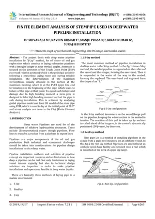
  • 1. International Research Journal of Engineering and Technology (IRJET) e-ISSN: 2395-0056 Volume: 06 Issue: 05 | May 2019 www.irjet.net p-ISSN: 2395-0072 © 2019, IRJET | Impact Factor value: 7.211 | ISO 9001:2008 Certified Journal | Page 6269 FINITE ELEMENT ANALYSIS OF STEMPIPE USED IN DEEPWATER PIPELINE INSTALLATION Dr.SHIVARAJ A M1, NAVEEN KUMAR T2, MANJU PRASAD J3, KIRAN KUMAR G4, SURAJ H BHOYITE5 1,2,3,4,5Students, Dept. of Mechanical Engineering, BITM College, Karnataka, INDIA ---------------------------------------------------------------------***--------------------------------------------------------------------- Abstract - The project deals with deep water pipeline installation by “J-Lay” method, for off shore oil and gas exploration which consists in laying submarine pipelines with a straight stinger at near vertical angles. Attention is focused on the detection of the Touch Down Point (TDP) (to vessel relative position) which is the principal point for following a prescribed laying route and having reliable installation. The determination of the maximum stress/strain, usually attained in the section at the maximum bending, which is at the PLET (pipe line end termination) or the beginning of the pipe, which leads to failure of the pipe at that point. To avoid such failure and damage due to high bending moment a stem pipe is designed to take high bending moment so that the pipe is safe during installation. This is achieved by analyzing global pipeline model and local 3D model of the stem pipe using FEM, which is used to lay at the initial point of PLET and stress analysis are done in the FEA (Finite Element Analysis). 1. INTRODUCTION Deep water Pipelines are used for of the development of offshore hydrocarbon resources. These include (Transportation) export though pipelines. Flow lines to transfer a product from a platform to export lines Pipelines are major components of the oil and gas production. Both technical and economical challenges should be taken into considerations for pipeline design installations in ultra-deep water. Pipeline installation methods and selection of pipeline concept are important concerns and set limitations to how deep a pipeline can be laid. Not only limitations to laying vessel tension capacity but also to technical design solutions are important in order to make pipeline installations and operations feasible in deep water depths. There are basically three methods of laying pipe in a marine environment 1. S-lay 2. Reel lay 3. J-lay 1.1 S-lay method The most common method of pipeline installation in shallow water is the S-lay method. In the fig-1 shows S-lay method, the welded pipeline is supported on the rollers of the vessel and the stinger, forming the over-bend. Then it is suspended in the water all the way to the seabed, forming the sag-bend. The over-bend and sag-bend form the shape of an ‘‘S.’’ Fig-1 S-lay configuration In the S-lay method, tensioners on the vessel/barge pull on the pipeline, keeping the whole section to the seabed in tension. The reaction of this pull is taken up by anchors installed ahead of the barge or, in the case of a dynamically positioned (DP) vessel, by thrusters. 1.2 Reel lay method Reel pipe lay is a method of installing pipelines in the ocean from a giant reel mounted on an offshore vessel. In this fig-2 the reel lay method Pipelines are assembled at an onshore spool-base facility and spooled onto a reel which is mounted on the deck of a pipe lay barge. Fig-2:-Reel lay configuration
  • 2. International Research Journal of Engineering and Technology (IRJET) e-ISSN: 2395-0056 Volume: 06 Issue: 05 | May 2019 www.irjet.net p-ISSN: 2395-0072 © 2019, IRJET | Impact Factor value: 7.211 | ISO 9001:2008 Certified Journal | Page 6270 1.3 J-lay method In areas where the water is very deep, the S-lay system may not be appropriate because the pipeline leaves the stinger to go almost straight down. To avoid sharp bending at the end of it and to mitigate excessive sag bending, the tension in the pipeline would have to be high. Doing so would interfere with the vessel's positioning, and the tensioner could damage the pipeline. A particularly long stinger could be used, but this is also objectionable since that structure would be adversely affected by winds and currents. The J-lay system, one of the latest generations of lay-barge, is better suited for deep water environments. In this system, the pipeline leaves the vessel on a nearly vertical ramp (or tower). There is no overbend only a sagbend of centenary nature (hence the J notation), such that the tension can be reduced. The pipeline is also less exposed to wave action as it enters the water. However, unlike for the S-lay system, where pipe welding can be done simultaneously at several locations along Fig-3:- J-lay method The vessel deck's length, the J-lay system can only accommodate one welding station. Advanced methods of automatic welding are used to compensate for this drawback. 2. Problem Statement To design and analyse a pipe that would prevent the failure of the pipe used in J-lay deepwater pipeline installation. 3. Purpose & Scope The purpose of this document is to verify that the FTA stem pipes with their respective stiffeners, forgings and pipelines designed to meet the allowable stress (ASD) criteria in accordance with DNV-OS-F101. The stem pipes covered in this report include the following:  10.75”/14” FTA Production Stem Pipe The functional loadings of the stem pipe imposed on the FTA and ITA structures are also included in this report. 4. METHODOLOGY To avoid the fracture and damages occurred in the pipe used for the initial installation of the deep water pipeline system. Stem pipe is recommended to use during the installation of deep water pipeline which may sustain the pressure and loads occurred during installations. This stem pipe is modeled in solid works software. Stem pipe is similar to normal pipe used in deep water installation which consists of tapered fins to sustain such loads. This 3D model of Stem pipe is imported to ANSYS (finite Element Analysis). To the stress analysis for the bending loads (installation loads). The load include external pressure pipeline and PLET weight acting axially (vertically) bending moment. 4.1. Designing of Stem Pipe The modeling of stem pipe is carried out in Solidworks software, where Solidworks software is used to create engineering models. Building a model in solidworks usually starts with a 2D sketch, the parts of stem pipe were initially drawn in the 2D sketch then they are converted into 3D parts. Similarly each and every parts of the stem pipe is created with respective geometry(dimensions) and they are assembled to from a 3D model of stem pipe. Fig-4:-Design of stempipe Fig-5:-Design of stempipe
  • 3. International Research Journal of Engineering and Technology (IRJET) e-ISSN: 2395-0056 Volume: 06 Issue: 05 | May 2019 www.irjet.net p-ISSN: 2395-0072 © 2019, IRJET | Impact Factor value: 7.211 | ISO 9001:2008 Certified Journal | Page 6271 Fig-6:-simple pipe with block Fig-7:-stempipe with stiffeners Tab 1:- Stempipe size & material Item Value Units Pipe without stiffeners Outside Diamter 355.6 mm Wall Thickness 20.6 mm Material DNV SML 485 U - Total Pipe Length 31000 mm Tab 2:-Stiffener Details 4.2. Installation of Loads The stem pipes are welded onshore to FTA and ITA prior to the transportation to the installation site. Installation analyses of the FTA with stem pipe were carried out and the installation loads experienced by the production and service flow line stem pipes on the FTA structure are obtained from installation contractor. Fig6 shows the direction of the force and moments defined in the FTA installation analysis. Fig 8:-Installation Loads on Typical FTA Present the forces and moments on the FTA stempipe obtained from installation contractor to be used in the stem pipe modelling. The worse case between the 1st and 2nd end FTA obtained from installation contractor is presented here. These installation loads are applied to the stem pipe model to determine if the stem pipe is within the DNV OS F101 ASD obtained from installation contractor during installation. The installation load obtained from installation contractor had considered a dynamic amplification factor (DAF) of 1.2. Both these loads have been considered in the modelling to determine the stress range for fatigue analysis due to dynamic installation loads. In the ANSYS 18.1 the structural analysis was done with the above loads on the normal pipe and stempipe, where results are calculated and compared. Note:-The sign convention of the force and moments shown in this table refers to the load directions shown in fig. Tab 3:- FTA Loading Conditions for Production Flowlines during Installation Flowline Case Descript ion Vertical Moment on Stem pipe, Mz[kNm] Tension, T [kN] 10.75”/1 4” Installati on Static DAF=1.0 -1415 578 10.75”/1 4” Installati on Dynamic DAF=1.2 -1698 693.6 Item Value Units Pipe with stiffeners Outside Diamter 355.6 mm Wall Thickness 20.6 mm Material DNV SML 485 U - Total Pipe Length 31000 mm Stiffener section Length 10800 mm Pipe section Length 20200 mm Descripition Value Units Material Strutural Steel - Young’s Modulus 207 MPa Poisson’s Ratio 0.3 - Density 7850 Kg/m3 Tensile Yield Strength 250 MPa Tensile Ultimate Strength 460 MPa Fy Mz Tension
  • 4. International Research Journal of Engineering and Technology (IRJET) e-ISSN: 2395-0056 Volume: 06 Issue: 05 | May 2019 www.irjet.net p-ISSN: 2395-0072 © 2019, IRJET | Impact Factor value: 7.211 | ISO 9001:2008 Certified Journal | Page 6272 To ensure that all the stem pipes are adequately designed to prevent stresses and fatigue over the allowable limit for all conditions, the following cases listed in Table 3 are analyzed for the installation and operating conditions respectively. 5. RESULTS Tab 3 presents the loading from the production flowline FTA and ITA stem pipes. The force and moment are obtained from the ANSYS model and are used in the localized ANSYS Workbench local stem pipe model and also used for further FTA structural analysis. It is not possible to exactly reproduce the operating loads of the global pipeline model in the stem pipe local model. It is assumed that the bending loads are more important to the design of the stem pipes than the shear load at the stem pipe/structure interface and for this reason, the moment distribution along the stem pipe is modelled accurately whilst shear force is not. Results of the pipe without stiffeners Fig 9:-Directional deformation of pipe without stiffeners in Y-direction Fig 10:-Directional deformation of pipe with stiffeners in Y-direction Fig 11:-The cut section view of Directional Deformation, normal stress, Von Moses stress & Elastic strain. Fig 12:-Elastic Strain Fig 13:-Normal Stress Fig 14:- Von Moses stress
  • 5. International Research Journal of Engineering and Technology (IRJET) e-ISSN: 2395-0056 Volume: 06 Issue: 05 | May 2019 www.irjet.net p-ISSN: 2395-0072 © 2019, IRJET | Impact Factor value: 7.211 | ISO 9001:2008 Certified Journal | Page 6273 Tab:-4 Represent the comparison results of both pipes Results single pipe without stiffener Pipe with stiffeners Units Deformation in –y plane 10618 0.31035 Mm Normal stress 1237.7 110.18 MPa Von Moses stress 1572.9 241.81 MPa Elastic strain 0.0070131 0.0005645 MPa Table presents the results of Von Moses stress, Normal stress, and Elastic strain for the 10.75”/14” stem pipe during Installation Case 1 condition. Tab:-5 Case 2 results for pipe with stiffeners Results Pipe with stiffeners Units Deformation in –y plane 0.29627 mm Normal stress 215.31 MPa Von Moses stress 230.77 MPa Elastic strain 0.0010018 MPa Table presents the results of Von Moses stress, Normal stress, and Elastic strain for the 10.75”/14” stem pipe during Installation Case 2 condition. 6. CONCLUSIONS From the analysis of the stem pipe design for installation and operating cases (as shown in Table 2-3 to Table 2-5), the following conclusion can be made: 1. The design of stiffeners and stem pipe configuration of 10.75”/14” production flowline FTA stem pipe is acceptable in operating condition. 2. ” 10.75”/14” production flowline ITA stem pipe configuration with the stiffeners are acceptable for both installation and operating conditions although a small spot of high stress occurs in the installation case 3. The design of stiffeners and stem pipe configuration of 10.75” and service flowline FTA stem pipe is acceptable for operating condition although small spot of high stress occurs. 7. REFERENCE 1. John Oluwasegun Oladimeji, Chinwuba Victor Ossia, John Umunna Okol. Offshore Technology Institute (OTI), ETF Gas Engineering Building, University of Port Harcourt, Port Harcourt, Nigeria, “On the Structural Integrity of J-Lay Method of Pipeline Installation” American Journal of Mechanical Engineering, vol. 4, no. 4 (2016) 2. Morten B. Langhelle, Offshore Technology/ Marine and Subsea Technology “Pipelines for Development at Deep Water Fields” 3. Senthil Ba, R Panneer Selvamb M.Tech student,Dept of Ocean Engineering, IITM, Chennai, “Dynamic Analysis of a J-lay pipeline”. Procedia Engineering 116 (2015) 730 – 737 4. S. Lenci and M. Callegari, Ancona, Italy “Simple analytical models for the J-lay problem” 5. M. Callegari, c.b. carini, s. Lenci, e.Ttorselletti and. Vitali, Aimeta. “DYNAMIC MODELS OF MARINE PIPELINES FOR INSTALLATION IN DEEP AND ULTRA-DEEP WATERS” 6. Vasques, T. 2017. Institute Superior Técnico, Portugal. “Analysis of Submarine Pipelines Installation through Progressive Immersion Method” 7. S. Ivić – M. Čanađija1 – S. Družeta Faculty of Engineering, University of Rijeka, Faculty of Engineering “STATIC STRUCTURAL ANALYSIS OF J-LAY PIPE LAYING WITH A TENSIONER MODEL BASED ON THE FRICTIONAL CONTACT”