More Related Content
Similar to Loadtestinghandbook
Similar to Loadtestinghandbook (20)
Loadtestinghandbook
- 1. Federation of Piling Specialists
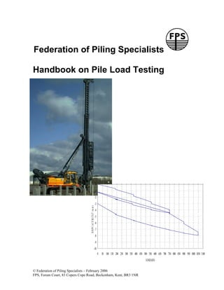
Handbook on Pile Load Testing
0
-1
-2
-3
D IS P L A C E M E N T (m m )
-4
-5
-6
-7
-8
-9
-10
0 50 100 150 200 250 300 350 400 450 500 550 600 650 700 750 800 850 900 950 1000 1050 1100
LOAD (kN)
© Federation of Piling Specialists – February 2006
FPS, Forum Court, 83 Copers Cope Road, Beckenham, Kent, BR3 1NR
- 2. Foreword
This handbook was published in March 2006 by the Federation of Piling Specialists
(FPS) to provide guidance on the principles and practical issues that relate to load
testing of bearing piles, and thereby to assist informed decisions about testing
requirements on construction projects involving piled foundations.
The FPS anticipates that this handbook will be of particular interest to civil or structural
engineers with little or no experience of piling who find themselves in the position of
specifying load testing requirements on a project involving piled foundations. The target
audience for this publication also includes main contractors, management contractors
and young piling engineers.
The handbook was prepared for publication by a working group comprising the following
representatives of FPS member companies: -
Bob Handley Aarsleff Piling (Chair)
Jon Ball Roger Bullivant
Andrew Bell Expanded Piling
Tony Suckling Stent Foundations
The Safety and Training Forum of the FPS were invited to review the final draft of the
handbook, in particular the chapter on safety. Their suggestions and comments (for
which the working group are most grateful) have been incorporated into the finished
handbook.
The FPS acknowledges, with thanks, information and photographs contributed by the
following: -
Aarsleff Piling
Dr. Michael Brown, University of Dundee
LOADTEST
Precision Monitoring & Control (PMC)
Roger Bullivant
Stent Foundations
Ken Cameron and Martyn Ellis of PMC carried out an independent review of the final
draft of the handbook, for which the FPS wishes to express its thanks.
To the fullest extent permissible by law, the FPS, the authors of, and contributors to this
handbook each disclaim all responsibility for any damages or losses (including, and
without limitation, financial loss, damages for loss in business projects, loss of profits or
other consequential losses) arising in contract, tort or otherwise from any action or
decision taken as a result of using this handbook.
© Federation of Piling Specialists – February 2006
FPS, Forum Court, 83 Copers Cope Road, Beckenham, Kent, BR3 1NR
2
- 3. Chapter 1 Introduction
Year on year, load testing of bearing piles represents an estimated 4 to 6% of the total
value of the UK piling market. The cost of load testing on individual contracts can vary
from zero in many cases to as much as 10% of the value of the piling works. One aim of
this handbook is to provide guidance on an overall strategy with the aim of promoting
better specification, planning and execution of pile testing.
A lack of clear objectives often means that expenditure on load testing may be at best
poorly allocated or at worst wasted. The testing requirements may well be set simply to
comply with the relevant regulations and to follow “common practice”, rather than to
promote “best practice”.
The ability of load testing to play an important part in value engineering and the
geotechnical and structural optimisation of foundation solutions should be recognised not
only in financial terms, but also with regard to sustainability.
It is important, therefore, that load testing of piles is factored into the project cost plan and
programme at an early stage. The programme should allow sufficient time for an objective
appraisal of the test results and subsequent design revisions/value engineering to be
carried out.
A lack of clear objectives and understanding combined with poorly specified requirements
can lead to problems that could have been avoided. Examples of such problems are: -
• Insufficient time to carry out tests and to evaluate the test results
• Lack of flexibility in the testing regime
• No provision for value engineering
• Unrealistic performance criteria specified
• Inappropriate test method specified
• Load test conditions are not representative of the working piles
• Piles infrequently loaded to failure
Pile load testing provides an opportunity for continuous improvement in foundation design
and construction practices, while at the same time fulfilling its traditional role of design
validation and routine quality control of the piling works. In order to achieve this
improvement, data from pile tests has to be collected and analysed to enable the piling
industry, both individually and collectively, to make the best use of resources.
To justify its cost to the industry, pile testing must have a value. The magnitude of this
value will be increased through a better understanding of the process and its benefits.
In this handbook the Federation of Piling Specialists aims to provide guidance on issues
that should be considered to enable better planning, specification and execution of pile
tests, thereby increasing the value of the testing process.
© Federation of Piling Specialists – February 2006
FPS, Forum Court, 83 Copers Cope Road, Beckenham, Kent, BR3 1NR
3
- 4. Chapter 2 Safety
Key safety issues must always be considered in the planning and execution of pile load
tests, including the following: -
2.1 Preparation and Maintenance of Test Area
• The area surrounding the test pile must be cleared of pile spoil, slurry and rubbish.
• A properly designed level platform of sufficient plan dimensions to support the testing
equipment safely and with suitable access for operatives, transport vehicles and
lifting plant must be provided. The working platform for lifting plant must be designed
to withstand the loads applied by tracks or out-riggers.
• Construction plant that may be operating elsewhere on site must be excluded from
the test area during the course of the pile test so that the test pile's performance can
be accurately monitored in a safe environment.
• Electronic barriers with audible warnings can be used to keep the test area clear, and
under no circumstances will any excavations be permitted within the exclusion
zone.
2.2 Lighting
• Dependant upon the loading regime agreed it may be required that some
operations are carried out during periods of poor natural lighting or darkness; the
area must be adequately lit to enable the load test to be undertaken safely and for
the test pile performance to be monitored throughout the full duration of the test.
2.3 Load application limits
• The maximum test load to be applied must be agreed in advance so that the test pile,
pile cap (if required) and the load testing equipment (reaction piles/kentledge/
hydraulic ram and pump/bi-directional load cell/rapid or dynamic test energy) can all
be designed or chosen so as to apply the maximum test load safely.
• When it is the intention to test a pile to geotechnical failure, due consideration must
be given to the capacity of the whole test system. If geotechnical failure of the test
pile has not occurred on application of the maximum test load, then this fact should
be accepted. Increasing the load beyond the safe design capacity of the test system
must not take place.
• All supervisory site staff must be made aware of the specification and the loading
regime to be followed, and also the agreed method statements and risk
assessments relating to the load test.
• During the course of the load test the whole system should be monitored for
eccentricities and appropriate actions taken if this becomes excessive.
© Federation of Piling Specialists – February 2006
FPS, Forum Court, 83 Copers Cope Road, Beckenham, Kent, BR3 1NR
4
- 5. • Systems using only two reaction piles are inherently less stable than those with
three or more and consequently should only be considered where test loads are
light and the ground conditions permit location of the reaction piles to more
stringent tolerances than normal.
• If any anomaly occurs during the load test that could give rise to an unsafe
situation, such as those illustrated in Figures 2.1 and 2.2, no further loading should
be applied in order to prevent these happening. The test area should be cleared
immediately and advice sought from the pile testing contractor.
2.4 Site operative instructions
The issuing of correct and concise instructions to suitably experienced site personnel is
essential for the safe completion of a load test on a pile.
• Where possible, standard testing equipment and loading procedures should be used.
Consistency in the equipment set up and loading procedure will reduce the possibility
of errors occurring, although the risk of complacency should not be overlooked. The
relative plan position, vertical alignment and fit of the component parts of the set
up should be checked to ensure that these are within permissible tolerances and
prior to the application of load the set up should be checked for any eccentricity of
loading. The equipment should be “self- stable”.
• Proper operative training and the use of written method statements for setting
up/dismantling the test equipment and the application of the load are essential.
• The setting up and dismantling of kentledge tests involves operatives working at
height and alternative methods of providing the reaction for the test load should be
adopted wherever reasonably practicable.
• If the load test involves out of hours working, a safe system of operation should be
established and agreed in advance. This may require a minimum of two people
present on site during the duration of the test.
• Pile load tests harness significant amounts of energy and if this energy is not
controlled in a safe manner it presents a significant safety hazard. Failures can occur
rapidly with little or no warning. Site personnel must therefore be made aware that
correct test procedures must always be followed.
• The use of readily available remotely operated methods of applying the load and
measuring pile movement is recommended to avoid the site personnel being close to
the testing equipment during the course of the test, particularly during the loading and
unloading cycles of the test.
• The relative levels of the top of the test pile cap and the underside of the main
reaction beam should be arranged so as to minimise the depth of any additional
packing above or below the load train which might otherwise lead to some instability
in this area of the test set up.
© Federation of Piling Specialists – February 2006
FPS, Forum Court, 83 Copers Cope Road, Beckenham, Kent, BR3 1NR
5
- 6. Figure 2.1 Failure of tension bar system in reaction pile
Figure 2.2 Platform bearing failure under kentledge test
© Federation of Piling Specialists – February 2006
FPS, Forum Court, 83 Copers Cope Road, Beckenham, Kent, BR3 1NR
6
- 7. Chapter 3 Testing Strategy
3.1 Strategy
This chapter concentrates on vertical load tests on piles. However, most of the
recommendations in this chapter are equally valid for load tests on raking piles, tension
piles and for the lateral load testing of piles. It is essential to seek expert advice for these
types of pile test.
The strategy for pile testing needs to be established at the time the piles are being
designed. For most projects the main purpose of pile testing is either to validate the
design before construction and/or to check compliance with the specification during
construction. However in some cases there are benefits in using testing for design
development or research to provide the best solution. Testing strategies can therefore be
divided into four main categories: -
• Design validation
• Quality control
• Design development
• Research
The scope of testing will depend on the complexity of the foundation solution, the nature of
the site and the consequences if piles do not meet the specified requirements. The pile
designer therefore needs to assess the risks and develop the testing regime accordingly.
The main risks are: -
• insufficient site investigation
• lack of experience of similar piles in similar ground conditions
• insufficient time to verify the pile design and realise any savings
• cost and programme implications of undertaking the pile tests
• cost and programme implications of a foundation failure
For simple structures on a site where the ground conditions are well understood and there
is pile test data from adjacent sites that have used similar piling solutions, then the risks
are low and pile load testing can usually be restricted to routine checks for compliance or
can even be omitted.
For situations where the ground conditions or structural requirements are complex, or
there is little experience of similar piling work, then careful evaluation of the piling
proposals is essential prior to embarking on the main piling works. Here the testing regime
may need to be considered in two phases comprising preliminary pile testing before the
main piling works and then proof testing of working piles.
The testing strategy for pile testing should address a project-specific set of stated
objectives, which should include the following: -
• to minimise risk by investigating any uncertainties about the ground conditions,
contractor’s experience or new piling techniques
• to optimise the pile design in terms of size, length and factor of safety
© Federation of Piling Specialists – February 2006
FPS, Forum Court, 83 Copers Cope Road, Beckenham, Kent, BR3 1NR
7
- 8. • to confirm any pile installation criteria such as founding strata identification, pile set
or pile refusal criteria
• to assess buildability, site variability, pile uplift, soil remoulding along the pile shaft
or relaxation at the pile toe
• to check that the pile performance meets the required load/settlement behaviour
during loading
• to assess environmental impacts of noise, vibration or pollution
In Table 3.1 below the level of risk is related to the characteristics of the piling works. The
pile testing strategy varies according to this level of risk.
Characteristics of the
piling works Risk level Pile testing strategy
Complex or unknown ground Both preliminary and working pile
conditions. tests essential.
No previous pile test data. High 1 preliminary pile test per 250 piles.
New piling technique or very 1 working pile test per 100 piles.
limited relevant experience.
Consistent ground conditions. Pile tests essential.
No previous pile test data. Medium Either preliminary and/or working pile
Limited experience of piling in tests can be used.
similar ground. 1 preliminary pile test per 500 piles.
1 working pile test per 100 piles.
Consistent ground conditions. Pile tests not essential.
Previous pile test data is If using pile tests either preliminary
available. Low and/or working tests can be used.
Extensive experience of piling in 1 preliminary pile test per 500 piles.
similar ground. 1 working pile test per 100 piles.
Table 3.1
For pile tests in situations where the risk level is high, consideration should be given to using
instrumentation within the pile, employing either strain gauges or fibre optics.
Where piles are required to carry very heavy loads, it may be uneconomic to carry out full
scale standard load tests. In such circumstances, consideration can be given to carrying out
tests on smaller diameter piles using the same method of construction (as provided for in
EC7 for example), provided the results of the tests can be extrapolated with some degree of
confidence to predict the load settlement characteristics of the larger piles. The test piles
should be founded at the same level and in the same soil as the works piles. Alternatively, a
bi-directional pile test with an O-cell cast into the pile can be used.
For rapid loading and dynamic pile tests it may be necessary to increase the applied loads to
the pile in order to overcome the ground damping effects. Calibration with static load tests is
preferable, depending on the prevailing ground conditions.
© Federation of Piling Specialists – February 2006
FPS, Forum Court, 83 Copers Cope Road, Beckenham, Kent, BR3 1NR
8
- 9. For preliminary pile tests it is preferable to place the test pile(s) close to a borehole so that
the test results can be reliably evaluated.
Where the ground conditions are reasonably uniform over the site area, working test piles
should be located in positions that will give the best possible coverage of the area to be piled.
Where ground conditions vary across the site, the number of test piles may have to be
increased in order to check the pile characteristics in different areas of the site.
Care should be taken when choosing the test pile locations to ensure that there is sufficient
space available for the reaction system to be installed without interference with other piles on
the site. Consideration should also be given to the location of test piles in relation to the work
in progress on the site while the tests are being carried out. Vibrations from other works can
interfere with the test pile results and a test being carried out at an inconvenient location will
disrupt other works on site.
For projects with a very large number of piles, say over 1000, the number of test piles can be
reduced below that recommended in Table 3.1, once the pile designer can demonstrate
confidence in the ground conditions and the pile construction method.
3.2 Acceptance criteria
The Performance Specification must state the maximum settlement permitted on an
individual pile during load testing at the design verification load (DVL). It is the
responsibility of the Engineer, when choosing this settlement value, to assess the effects
of pile group action and the sensitivity of the structure to differential movement.
For insensitive buildings, the maximum settlement permitted at the head of an individual
pile during load testing at DVL should be 10mm plus the calculated elastic shortening of
the pile shaft, for piles less than 1000mm diameter. For test piles greater than 1000mm
diameter a value in excess of 10mm may be appropriate.
Maximum settlement at loads greater than DVL should not be specified for insensitive
buildings.
If the measured pile settlement exceeds the permitted value then the pile designer and the
piling contractor should investigate the causes and undertake appropriate remedial action,
if any.
© Federation of Piling Specialists – February 2006
FPS, Forum Court, 83 Copers Cope Road, Beckenham, Kent, BR3 1NR
9
- 10. Chapter 4 Testing and Specification
4.1 Types of pile test
The various available methods of testing piles are best characterised by the duration that the
force is applied to the pile and the strain induced in the pile. Tests involving large forces
applied for long periods of time such as static load tests are used to assess pile load capacity
and small energy low strain tests are used to assess pile integrity. In high strain dynamic and
rapid load tests, although the force is comparable in magnitude to a static test, it is applied
over a much shorter period than in a static load test. Careful consideration is therefore
needed in the interpretation of the dynamic effects in order to derive static load capacities.
The various types of test and their application are summarised below. More details of
individual testing methods are included in Chapter 5 ‘Load Testing Methods’.
The static load test relies on a suitable reaction system from which to apply loading to the
pile under test. Typical reaction systems are described in Chapter 5.
Instrumentation may be built into preliminary test piles to investigate the load transfer
mechanism during the test. Piles may be equipped with strain gauges, push rods, load
cells and other devices to enable the designer to isolate key pieces of information and
improve the analysis of the test result and confirm or refine the design approach. This
type of equipment is normally of a specialist kind and requires careful selection,
installation and additional monitoring. It is preferable to have specialist advice on the
installation, monitoring and testing of any instrumentation.
At present, the most frequently used types of static load testing are the Maintained Load Test
(MLT) and the Constant Rate of Penetration Test (CRP). Both manual and automated test
methods are suitable for either type of test.
For further information on the MLT or CRP load test procedure refer to the ICE
Specification for Piling and Embedded Retaining Walls.
4.1.1 Maintained Load (MLT) Test
In the MLT, the load is applied to the pile in discrete increments and the resulting pile
movement/settlement monitored. Subsequent load increments are only applied when the
minimum specified time period has elapsed and the rates of induced settlement are below
the specified criteria. The normal U.K. practice is to load the pile up to DVL, then to unload
back to zero loading. Subsequent load cycles are applied, taking the loading to specified
values above the DVL depending on the requirements of the test. The test will normally last
between 24 and 48 hours excluding erecting and dismantling the test equipment.
The MLT method is normally the most suitable in determining the load/settlement
performance of a pile under working loads and at 1.5 times working load conditions.
4.1.2 Constant Rate of Penetration (CRP) Test
In the CRP test, the load required to cause a pile to penetrate into the ground at a constant
rate is monitored until either the maximum specified test load is achieved or "failure" of the
pile occurs. The performance of the test takes less than 24 hours excluding erecting and
dismantling the test equipment.
© Federation of Piling Specialists – February 2006
FPS, Forum Court, 83 Copers Cope Road, Beckenham, Kent, BR3 1NR
10
- 11. The measured penetration of the pile is plotted against the load applied, the purpose of
the test being to determine the ultimate bearing capacity of the pile, particularly for piles
constructed within predominantly cohesive material and deriving their capacity mainly in shaft
friction. However, due to the high rate of loading, the measured maximum soil resistance
may over-predict the ultimate capacity.
4.1.3 Bi-directional Load Cell
Another form of MLT uses a bi-directional load cell. This system is usually only applicable to
conventional auger bored piles carrying high axial loads. The method is described in detail in
Chapter 5, and involves a load cell or cells placed in the pile bore either at the pile base or
part of the way up the pile shaft during the concreting operation. In the test the cell is
hydraulically expanded so the upper part of the pile reacts against the lower part.
4.1.4 Rapid Load Test
Rapid Load Tests use a combustion chamber to provide a rapid load application to the pile
head. The length of the stress wave in these tests is sufficiently long to encompass the whole
pile and therefore there is no need for complex wave equation analysis when interpreting the
results. However, in common with the dynamic load test, effects of creep and pore water
dissipation can influence the results although to a slightly lesser extent because the rate of
loading is lower.
4.1.5 Dynamic Load Test
These methods are based on monitoring the response of a pile subjected to hammer blows
applied at the pile head. The measured response parameters are subsequently analysed to
give predictions of the soil resistance that would be mobilised by the pile under static load
conditions, based on stress wave theory.
The analytical models of the pile/soil interaction have been further developed to provide
prediction of the load/settlement performance of the tested pile.
Developed initially for use with driven piles and now universally accepted, dynamic load
testing of cast in place piles is now quite widely used to predict the static soil resistance and
the load/settlement behaviour. The test method is similar to that used on driven piles with
the monitoring of hammer blows and subsequently analysing the pile response to the stress
wave propagation. A separate hammer or drop weight is usually brought to site to allow the
dynamic load to be applied to a cast in place pile.
Due to the very high rate of applied loading, dynamic load testing cannot take into account
time-related effects such as consolidation, relaxation or creep; consequently care should be
exercised in reviewing the results of tests carried out in soils which may exhibit these
features. However, the use of dynamic testing after calibration within a particular geological
profile will allow more comprehensive testing at low cost in comparison to static testing.
Typically a dynamic test will take about 15 minutes to perform on a precast concrete pile
using the piling rig hammer to 30 minutes on a bored cast in place pile requiring the use of a
separate drop weight.
4.1.6 Summary
Table 4.1 on page 12 summarises the types of pile load tests as described above.
© Federation of Piling Specialists – February 2006
FPS, Forum Court, 83 Copers Cope Road, Beckenham, Kent, BR3 1NR
11
- 12. Test Type Reaction System Maximum Test Advantages Disadvantages
Load
Static Reaction piles 30MN Suits all soil Reaction piles/kentledge and
Maintained (Rock anchors may (generally) conditions and frame are required.
Load (MLT) provide an pile types. Kentledge tests are relatively
alternative reaction Manual and expensive. Setting up and
system for piles end automated dismantling the test equipment
bearing in rock) systems involves operatives working at
available. height.
Kentledge 3MN Piles can be Long duration.
(generally) instrumented.
Tension and
In both cases lateral testing
higher test possible.
loads are
possible.
Bi-directional load 27MN per cell Very high test Relies on sophisticated pile
cell loads instrumentation and analysis.
achievable. Suits bored piles only.
No reaction Relatively expensive and long
system required.duration.
Static As for MLT As for MLT Suits all pile Reaction piles/kentledge and
Constant types. frame required.
Rate of Manual and Kentledge tests are relatively
Penetration automated expensive.
(CRP) systems Limited to cohesive soils.
available. May over predict ultimate load.
Rapid Load Combustion 30MN No reaction May require calibration with
Test chamber system required.static test.
Fast test. Caution required in cohesive
soils and in chalk.
Unsuitable for piles in excess
of 40m deep.
Suitable for testing pile groups
and piles of variable or
unknown pile shaft profile, e.g.
CFA piles or re-used piled
foundations.
Dynamic Piling hammer 3MN Fast and May require calibration with
or separate drop (generally, but relatively static test. Results may be
weight can be greater) inexpensive. unrepresentative in soils that
Hammer weight Suitable for both exhibit relaxation (reduction of
should be in the driven and end bearing in Coal Measure
range 1 to 2% bored piles. Mudstones for example).
of load to be Correlation with Correlation of dynamic and
proved. static tests on static results on piles in
bored piles cohesive soils and chalk must
generally good. consider time-related effects
and the length of pile tested.
© Federation of Piling Specialists – February 2006
FPS, Forum Court, 83 Copers Cope Road, Beckenham, Kent, BR3 1NR
12
- 13. Table 4.1
4.2 Specification
4.2.1 Test Procedure
All load tests should be carried out in accordance with the ICE Specification for Piling and
Embedded Retaining Walls.
4.2.2 Maximum Test Load
Load tests on preliminary or non-working test piles, in advance of or during the early stages
of the piling works, are normally carried out to DVL plus 1.0 or 1.5 times the specified
working load (SWL). DVL is the working load plus allowances for soil induced forces such as
downdrag or heave, and any other particular conditions of the test such as a variation of pile
head casting level.
Load tests on working piles are normally taken up to a maximum load of DVL plus 0.5 times
the specified working load. This is sufficient to verify the load settlement characteristics of
the piles under service conditions.
4.2.3 Concrete and Reinforcement
The strength of the concrete in the pile must be considered in all cases where a load test is
to be carried out, in order to ensure that the concrete is not over-stressed during testing. This
is particularly important with preliminary test piles where the stresses in the concrete may be
very high. Preliminary test piles are often loaded to between two and three times their normal
specified working load and this may call for higher grades of concrete than those to be used
in the works. There is no evidence to suggest that this affects the bearing capacity of a pile
within the limits of normal concrete strength. Enhanced reinforcement may also be required
in preliminary piles to prevent structural failure under such loading conditions.
For working pile tests, the test should not proceed until compressive tests on works cubes
have confirmed that the concrete strength is at least twice the concrete stress in the pile at
the maximum specified test load. It is also necessary to ensure that the trimmed head of the
pile is in intimate contact with the pile cap with a horizontal, clean and well formed joint.
Common examples of factors contributing to unsuccessful static load tests are: -
• Pile cap not concentric with pile shaft
• Poorly formed joint between pile head and pile cap
• Poorly designed/insufficient reinforcement in pile head or pile cap to withstand
bursting stresses
• Pile cap concrete of inadequate strength or poor quality
Pile head preparation of bored/CFA piles undergoing dynamic load testing is critical. Unless
the pile has a permanent liner, the pile shaft must be built up 2 to 3 pile diameters above
ground level at the pile position within a thin-walled liner, suitably reinforced and finished with
a smooth flat surface normal to the pile axis. A pair of diametrically opposed windows,
200mm square, must be cut into the liner to reveal smooth concrete surface to which the
gauges can be attached. CFA piles subject to dynamic load tests will require the main
reinforcement to extend to the pile toe. The heads of piles undergoing rapid load tests will
require similar pile head preparation to that necessary for static load tests.
© Federation of Piling Specialists – February 2006
FPS, Forum Court, 83 Copers Cope Road, Beckenham, Kent, BR3 1NR
13
- 14. Chapter 5 Load Testing Methods
5.1 Maintained Load Tests in Compression
This method of testing involves the use of a reaction system to allow the application of a
load to the test pile for an extended period of time. It therefore follows that when under
test, there can be a very significant amount of energy contained in the system and as such
they can be deceptively hazardous. It is therefore strongly recommended that only
experienced, specialised personnel are employed to carry out the process.
The ground conditions will generally dictate the method of application of the reaction,
which falls into three categories. Each method should be carried out using a suitably
robust load transference system.
5.1.1 Reaction Piles
Ground conditions, pile type and site constraints often make the use of reaction piles
economical. A number of reaction (anchor) piles can be placed surrounding the test pile
and will provide the required tensile capacity and act as reaction against the compression
test pile. Transfer of the forces involved is carried out by a series of beams, bars and
couplers as illustrated in Figure 5.1. The beams are placed over the piles and securely
connected by the couplers to high strength threaded bars cast into the anchor piles and
specifically designed for the purposes of the test.
As only a relatively small amount of equipment is required, the site footprint is relatively
small. The size of the testing apparatus is generally a function of the pile size and loading
to be applied. Reaction piles should be placed at a sufficient distance from the test pile so
as to avoid any interaction of soil resistances. In broad terms an area of at least 8m x 5m
is required for the test.
Measurement
Once assembled the deflection of the pile is measured using a number of dial gauges, or
electronic transducers arranged around the pile. The gauges are supported on a reference
beam attached to the ground at a suitable distance. Directly above the test pile, along its
axis, the load train is placed (see Figure 5.2). This consists of a jack, packer plates and
load measurement device in the form of a calibrated pressure gauge, mechanical proving
ring or ideally, a digital load cell.
© Federation of Piling Specialists – February 2006
FPS, Forum Court, 83 Copers Cope Road, Beckenham, Kent, BR3 1NR
14
- 15. Figure 5.1 30MN reaction pile test
© Federation of Piling Specialists – February 2006
FPS, Forum Court, 83 Copers Cope Road, Beckenham, Kent, BR3 1NR
15
- 16. Figure 5.2 Load Train
5.1.2 Kentledge
Should the ground conditions or site constraints preclude the use of reaction piles, the
alternative is to use kentledge. A frame is assembled over the pile to be tested on top of
which an amount of weight (a minimum 110 to 120% of maximum test load) is safely
stacked. This generally takes the form of concrete blocks of regular dimensions and
weight although steel ingots can be used provided that their weight can be assessed with
reasonable accuracy. The size of the testing apparatus is generally a function of the pile
size and loading to be applied. In broad terms an area of at least 15m x 15m is required
for the test (see Figure 5.3). At the time of assembly, the presence of the additional cranes
and associated transport deliveries will increase this working area. Consequently this is
the most costly and disruptive method of providing a reaction for load testing of piles in
compression.
Measurement
This method uses the same method as found in the reaction piles arrangement, as
illustrated in Figure 5.2.
Figure 5.3 3MN kentledge test
5.1.3 Bi-directional Method
This system is usually only applicable to conventional auger bored piles, and involves a load
cell or cells placed in the pile bore either at the pile base or part of the way up the pile shaft
during the concreting operation (see Figure 5.4). In the test the cell is hydraulically expanded
so the upper part of the pile reacts against the lower part. Schematic details of the testing
system are illustrated in Figure 5.5.
© Federation of Piling Specialists – February 2006
FPS, Forum Court, 83 Copers Cope Road, Beckenham, Kent, BR3 1NR
16
- 17. Where the cell is at the base of the pile, the soil at the base provides the reaction. More than
one cell can be provided to test different sections. There must however always be sufficient
shaft resistance from the pile section above the load cell to provide the necessary reaction
force to stop the pile being forced out of the ground.
Interpretation of the results is needed to derive a load/settlement plot and this can be
complicated. The test arrangement needs to be carefully designed to make interpretation as
straight forward as possible.
As there is no reaction frame assembly only a small working area is required, dictated by
the independent method of measurement.
Measurement
The load is quantified by measurement of the hydraulic pressure of the jack cast into the
pile. The reinforcement cage also allows the installation of extensometers to measure
movement.
Figure 5.4 Load cell in reinforcement Figure 5.5 Schematic details of system
5.1.4 Rapid Load Testing
This involves the assembly of a relatively small counterweight over the top of the test pile
and a controlled fast burning charge is then ignited in the mechanism. After combustion is
complete a hydraulic or mechanical catching mechanism safely brings the counterweight
to rest. Other methods provide extended duration of force by the use of springs and large
© Federation of Piling Specialists – February 2006
FPS, Forum Court, 83 Copers Cope Road, Beckenham, Kent, BR3 1NR
17
- 18. hydraulic hammer. The method is rapid allowing a large sample of piles to be tested and
the working area required is again a function of the magnitude of load required. Smaller
tests can be undertaken using a crawler mounted system (see Figure 5.6), while large
scale tests require an area in broad terms of at least 3m x 3m plus a working area for a
large attendant crane (see Figure 5.7).
Measurement
The charge controls the force imparted to the pile, which in turn is measured by a load cell
contained within the apparatus. Deflections are recorded by laser reference source and
photovoltaic cell or indirectly by an accelerometer.
Figure 5.6 Crawler mounted 1MN test
© Federation of Piling Specialists – February 2006
FPS, Forum Court, 83 Copers Cope Road, Beckenham, Kent, BR3 1NR
18
- 19. Figure 5.7 3MN capacity test
5.1.5 Dynamic Load Testing
In order to carry out this method of testing an impact hammer is required. The hammer
should ideally be sufficiently large to fully mobilise and therefore characterise the dynamic
pile capacity without damaging the pile, and in the case of driven piling will usually be the
same hammer as used to install the pile (see Figure 5.8). Dynamic load testing of bored
cast-in-place or CFA piles will generally require the use of a separate hammer or drop
weight (see Figure 5.9).
© Federation of Piling Specialists – February 2006
FPS, Forum Court, 83 Copers Cope Road, Beckenham, Kent, BR3 1NR
19
- 20. Dependant upon the method employed, electronic gauges are attached to the pile as
illustrated in Figures 5.10 and 5.11. The gauges measure the acceleration of the pile (and
therefore (indirectly) velocity with a knowledge of the pile properties) and strain within the
pile just below the head as the hammer strikes the pile. The information is then recorded
in the associated site computer. A variation of the method involves deflection
measurement directly by laser theodolite.
In addition to access for the piling hammer/drop weight only minimal access is required to
attach the gauges, provided that the pile shaft protrudes at least 2 to 3 pile
widths/diameters above ground level; this safeguards the gauges and allows the
propagation of a uniform stress wave.
A large number of piles can be tested in the course of one day using dynamic load testing
methods.
Analysis of data
Once the data has been recorded, it can then be analysed by suitably experienced
personnel using associated programs to provide the information on mobilised soil
resistance, pile integrity and hammer performance.
Figure 5.8 Dynamic load testing of driven precast concrete piles
© Federation of Piling Specialists – February 2006
FPS, Forum Court, 83 Copers Cope Road, Beckenham, Kent, BR3 1NR
20
- 21. Figure 5.9 Dynamic load testing of cast-in-place pile
Figure 5.9 Strain gauge and accelerometer bolted to precast concrete pile
The arrangement is repeated on the opposite pile shaft face
© Federation of Piling Specialists – February 2006
FPS, Forum Court, 83 Copers Cope Road, Beckenham, Kent, BR3 1NR
21
- 22. Figure 5.10 Bored cast in place/CFA pile head preparation with window cut in
liner to allow strain gauge and accelerometer to be attached to the pile
© Federation of Piling Specialists – February 2006
FPS, Forum Court, 83 Copers Cope Road, Beckenham, Kent, BR3 1NR
22
- 23. Chapter 6 Results and Interpretation
The ICE Specification for Piling and Embedded Retaining Walls sets out the requirements
of reporting the results of a load test.
6.1 Maintained Load Tests
6.1.1 Results
The results of an MLT on a bearing pile will comprise records of time, load and settlement
for the specified loading and unloading cycles and the periods of maintained load.
Computer controlled methods of load application and measurement in conjunction with
electronic transducer systems of settlement measurement enable accurate records of the
behaviour of the pile to be made and stored. Manual application of the load and the use of
dial gauges to measure settlement are becoming less frequently used as the remote
computer controlled methods provide a great improvement in operator safety and
consistency in carrying out the test procedure.
Whichever method of settlement measurement is used in the test, the results should
also include, where required by the particular specification, regular precise level
measurements taken on the datum beams onto which the electronic transducers or dial
gauges bear, as variations in temperature may cause some movement in these datum
beams which may distort the measurements.
The load test records will normally be presented in tabular form with pile settlement
recorded as the average of the displacement transducers or dial gauges at any point in
time. Modern methods of data storage allow the easy calculation of cumulative settlement
and increase in settlement during loading cycles (or recovery during unloading cycles), the
latter being required to verify that limiting rates of movement have been achieved prior to
increasing or decreasing the load on the pile. In addition to the numerical results, a
graphical plot of load versus deflection and a separately plot of load and deflection versus
time should also be included in the test results.
6.1.2 Interpretation of Results
Before embarking upon a detailed analysis of a set of load test results certain fundamental
issues should be considered: -
• Are the results accurate and consistent, or have they been subject to distortion by
some external influence such as weather effects or adjacent activities?
• Are the results in accordance with the designer’s expectations?
• Does the pile performance satisfy the specification, and if not what remedial
actions are required?
If a pile fully mobilises the soil resistance during a load test intentionally taken to failure or
when an unexpected premature failure occurs, the ultimate bearing capacity of the pile
should be as defined in the ICE Specification for Piling and Embedded Retaining Walls.
© Federation of Piling Specialists – February 2006
FPS, Forum Court, 83 Copers Cope Road, Beckenham, Kent, BR3 1NR
23
- 24. In the case of pile load tests that have not been taken to the point of failure of the pile/soil
interface, estimates of the failure load can be made using methods devised by Davisson,
Butler & Hoy, De Beer, Fuller & Hoy, Vander Veen, Brinsch Hansen, Mazurkiewicz or
Chin, all of which were compared by Bengt Fellenius in his paper published in Ground
Engineering in September 1980. It is not surprising to note a variation in predicted failure
load of 30% between the lowest predicted load (Davisson) and the highest (Chin) in a
comparison of the analysis of the same set of test results illustrated in the paper.
The Chin method also attempts to separate out components of shaft friction and end
bearing, but is only moderately successful when one or other of these components
predominates, in which case a review of the form of the load settlement plot will give a
reasonable indication. Acquisition, storage and manipulation of data by computers has
enabled more meaningful predictions of failure loads and proportions of the two
components, provided that a reasonable amount of end bearing is mobilised during the
test. Fleming (1992) is the most recent authoritative paper on this subject.
6.1.3 Recognising Problems from Test Results
In the event of a pile not performing as anticipated during an MLT, the shape of the load
settlement plot may give some indication of the reason for this. Tomlinson gives examples
of typical load settlement plots for a number of soil conditions and construction
irregularities in his book “Pile Design & Construction Practice”.
Examples of some commonly encountered problems are outlined in Table 6.1 below: -
Problem Reactive measures
Exceeding the permitted settlement Can structure accept the extra movement?
specification.
Preliminary test failing to prove Review design parameters and construction
required factor of safety. records; can the factor of safety be reduced?
Displacement pile has been lifted off Re-drive preformed piles if predominantly
its seating by ground heave and re- end-bearing; if friction piles check that
seated during the load test. settlement at DVL & DVL + 50%SWL is
within acceptable limits.
Soft toe results in excessive Review construction records; redesign piles
settlement or failure to increased FOS on shaft/wall friction;
construct piles to deeper toe levels; consider
a reduced SWL.
Structural failure in preliminary load Check concrete cube strengths (should be
test done before the test)
Table 6.1
It is important to appreciate that some margin between expected values of the load
settlement characteristic and the specified values is required to allow for natural variations
in ground conditions.
Equally important is an understanding that piles deriving their load bearing capacity
primarily in end bearing will usually settle more than those carrying the same pile head
© Federation of Piling Specialists – February 2006
FPS, Forum Court, 83 Copers Cope Road, Beckenham, Kent, BR3 1NR
24
- 25. load in shaft friction. The settlement of any pile will be influenced by pile type and length
as well as founding stratum soil type.
Elastic shortening of relatively highly stressed long piles of slender cross section will
contribute to greater settlements, up to as much as 25mm at working load in some cases.
6.2 Rapid Load Tests
6.2.1 Results
These test results take the form of an ‘equivalent static load test’ load deflection curve
after extraction of the dynamic loading effects, and the data is very similar to that obtained
in a constant rate of penetration test.
6.2.2 Analysis
Two main types of analysis of the field data may be employed, the unloading point
method (UPM) and the non-linear soil dependant approach.
The UPM identifies the point where the pile has zero velocity (unloading point) and
assumes that the pile resistance at this point is equivalent to the static pile resistance.
By considering the pile resistance between the peak applied load and the unloading
point a damping constant is found which is used to remove the rate dependent
component of the rapid load test. There are other variants of UPM such as the modified
unloading point method (MUPM) and the segmental unloading point method (SUPM).
These methods were developed for long piles (<40m) or piles with rock sockets and rely
on embedded instrumentation.
For skin friction piles in clays, ultimate capacity can be predicted using a non-linear
velocity dependant relationship as proposed by Randolph (2003), which has its origins in
the Smith wave equation analysis. This approach requires soil specific empirical
damping factors which may be obtained from high speed laboratory testing or back
analysis of rapid load tests.
6.2.3 Interpretation of Results
Rapid load testing is well suited for use in a proof load testing regime, and when used
correctly provides a quick and cost-effective method of verifying that both test and
working piles will meet a performance specification. However the method does have
certain limitations, such as: -
• The test loads may need to be specified to mobilise the toe resistance of the pile.
These loads may to be significantly greater than the loads required in a static test
due to rate effects (damping).
• The UPM analysis technique performs well in granular soils but may over predict
pile capacity by up to 50% in cohesive soils. However adjustment factors are
available to correct UPM results in different soil types.
• Non-linear viscous parameter based analysis performs well in cohesive soils but
is limited by the need for soil specific damping parameters.
© Federation of Piling Specialists – February 2006
FPS, Forum Court, 83 Copers Cope Road, Beckenham, Kent, BR3 1NR
25
- 26. • The predicted load deflection curve will not take into account creep or
consolidation effects.
Notwithstanding these limitations, the rapid load testing method has been used
worldwide since the late 1980’s and in the UK since the mid 1990’s. Although currently
not so widely used in the UK as in the United States and Japan, draft codes of practice
for ASTM and the Japanese Geotechnical Society have now been formulated. Guidance
on its use and analysis has also been produced for the US Transportation Research
Board and the Florida Department of Transportation.
6.3 Dynamic Load Tests
6.3.1 Results
The results of stress wave analysis carried out for piles that have been dynamically load
tested are normally presented as graphical presentations of the matching of measured
force and velocity traces against time, with a simulated load deflection curve for the pile
head and the pile toe. A graphical and tabular distribution of mobilised soil resistance is
also provided, together with pile stresses and hammer energy. CASE® analysis can be
performed also, but provides less information.
6.3.2 Analysis
Two types of analysis of the field data are possible, CASE® and CAPWAP®/SIMBAT®.
CASE® analysis calculates the dynamic resistance of the soil and using an empirical
damping factor relates this to the static resistance. The value of the damping factor can be
determined from the soil type at the pile toe to provide an early indication of soil resistance
on site at the time of testing, or back-analysed from the stress wave analysis to determine
a site specific value for sites with a reasonably consistent soil profile. CASE® analysis is
more suited to end bearing piles than friction piles.
CAPWAP®/SIMBAT® analysis involves the manipulation of a number of variables in the
program to obtain the best match between the force and velocity traces of the measured
and computed stress wave. These variables are static resistance, soil damping and soil
elasticity or quake, each being adjusted on the shaft and the toe of the pile.
Whereas CASE® analysis will only predict total mobilised soil resistance,
CAPWAP®/SIMBAT® stress wave analysis will proportion this resistance between shaft
friction and end bearing, as well as providing a predicted immediate load deflection curve.
6.3.3 Interpretation of Results
Dynamic load testing is well suited for use in a proof load testing regime, and when used
correctly provides an extensive and cost-effective method of verifying that piles will meet a
performance specification. However the method does have certain limitations, such as: -
• The mobilised static soil resistance will not necessarily represent an “ultimate
capacity” as full mobilisation of toe resistance often requires so much energy to
© Federation of Piling Specialists – February 2006
FPS, Forum Court, 83 Copers Cope Road, Beckenham, Kent, BR3 1NR
26
- 27. create the necessary movement per hammer blow that the pile may be damaged
during testing.
• Predicted soil resistances will generally be within plus or minus 15% when
compared with the results of a static load test. However, in certain soil conditions a
less satisfactory degree of correlation may be experienced.
• The predicted load deflection curve will not take into account creep or
consolidation effects, nor can it accurately model the onset of failure of the pile/soil
interaction.
Common reasons for apparently poor correlations between dynamic and static load test
results include: -
• Comparing results from different piles
• Time related set-up/relaxation effects
• Comparing piles of differing length
• Incorrect assumptions of soil type
Notwithstanding these limitations, the dynamic load testing method has been used in the
UK since the early 1980’s, during which time it has gained widespread acceptance within
the industry, becoming particularly popular in off-shore construction where traditional
methods of load testing piles are impractical.
© Federation of Piling Specialists – February 2006
FPS, Forum Court, 83 Copers Cope Road, Beckenham, Kent, BR3 1NR
27
- 28. Chapter 7 References
British Standard Code of Practice for Foundations BS 8004: 1996
BS EN 1997-1:2004 Eurocode EC7: Geotechnical Design - Part 1: General Rules
Chin Fung Kee, - Estimation of the ultimate load of piles from tests not carried to failure;
Proceedings of South East Asian Conference on Soil Engineering 1970
CIRIA PG7:1980 Pile Load Testing Procedures, A.J. Weltman
CIRIA 144:1997 Integrity Testing in Piling Practice
Fellenius, B.H., - The analysis of results from routine pile load tests; Ground Engineering
September 1980
Fleming, W.G.K., - A new method for single pile settlement prediction and analysis;
Geotechnique, September 1992
Goble, G.G., Likins, G.E., & Rausche, F., - Bearing Capacity of Piles from Dynamic
Measurements; Final Report, Department of Civil Engineering, Case Western Reserve
University March 1975
ICE Specification for Piling and Embedded Retaining Walls 1996
Middenthorp, P., Bermingham, P., and Kuiper, B., - Statnamic load testing of foundation
piles; 4th International Conference on Applied Stress Wave Theory of Piles, The Hague,
Balkema, Rotterdam 1992
Osterberg, J., - New device for testing driven and drilled shafts separates friction and end
bearing; Proceedings of International Conference Piling and Deep Foundations London
1989
Poulos, H.G., - Pile Testing – From a Designer’s Viewpoint; Proceedings of 2nd
International Statnamic Seminar Tokyo 1998
Paikowsky, S.G., - Innovative Load Testing Systems, Final Report by Geosciences
Testing and Research, Inc., Massachusetts, September 2004
Randolph, M.F. (2003) Science and empiricism in pile foundation design. Geotechnique
53, No. 10, pp. 847-875
Terzaghi, K., - Theoretical Soil Mechanics, 2nd Edition 1944
Tomlinson, M.T., - Pile Design & Construction Practice, first published 1977
Smith, E.A.L., - Pile Driving Analysis by the Wave Equation; Proceedings ASCE Volume
86 August 1960
© Federation of Piling Specialists – February 2006
FPS, Forum Court, 83 Copers Cope Road, Beckenham, Kent, BR3 1NR
28