Typified design of modified compound fink truss based on IS 800:2007 and IS 875(part 3):2015
•
0 likes•5 views

https://www.irjet.net/archives/V9/i6/IRJET-V9I6348.pdf

Recommended
Recommended
More Related Content
Similar to Typified design of modified compound fink truss based on IS 800:2007 and IS 875(part 3):2015
Similar to Typified design of modified compound fink truss based on IS 800:2007 and IS 875(part 3):2015 (20)
More from IRJET Journal
More from IRJET Journal (20)
Recently uploaded
Recently uploaded (20)
Typified design of modified compound fink truss based on IS 800:2007 and IS 875(part 3):2015
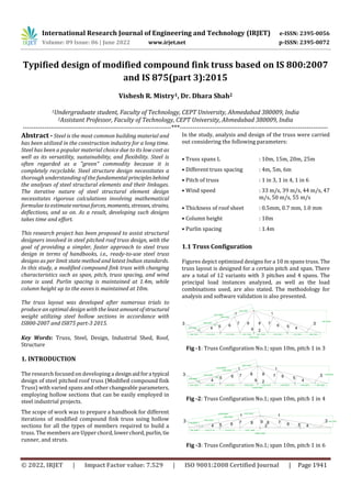
- 1. International Research Journal of Engineering and Technology (IRJET) e-ISSN: 2395-0056 Volume: 09 Issue: 06 | June 2022 www.irjet.net p-ISSN: 2395-0072 © 2022, IRJET | Impact Factor value: 7.529 | ISO 9001:2008 Certified Journal | Page 1941 Typified design of modified compound fink truss based on IS 800:2007 and IS 875(part 3):2015 Vishesh R. Mistry1, Dr. Dhara Shah2 1Undergraduate student, Faculty of Technology, CEPT University, Ahmedabad 380009, India 2Assistant Professor, Faculty of Technology, CEPT University, Ahmedabad 380009, India ---------------------------------------------------------------------***--------------------------------------------------------------------- Abstract - Steel is the most common building material and has been utilized in the construction industry for a long time. Steel has been a popular material choice due to its low cost as well as its versatility, sustainability, and flexibility. Steel is often regarded as a "green" commodity because it is completely recyclable. Steel structure design necessitates a thorough understanding of the fundamentalprinciplesbehind the analyses of steel structural elements and their linkages. The iterative nature of steel structural element design necessitates rigorous calculations involving mathematical formulae to estimatevariousforces, moments, stresses, strains, deflections, and so on. As a result, developing such designs takes time and effort. This research project has been proposed to assist structural designers involved in steel pitched roof truss design, with the goal of providing a simpler, faster approach to steel truss design in terms of handbooks, i.e., ready-to-use steel truss designs as per limit state method and latest Indian standards. In this study, a modified compound fink truss with changing characteristics such as span, pitch, truss spacing, and wind zone is used. Purlin spacing is maintained at 1.4m, while column height up to the eaves is maintained at 10m. The truss layout was developed after numerous trials to produce an optimal design with the least amountofstructural weight utilizing steel hollow sections in accordance with IS800-2007 and IS875 part-3 2015. Key Words: Truss, Steel, Design, Industrial Shed, Roof, Structure 1. INTRODUCTION The research focused on developing a designaidfora typical design of steel pitched roof truss (Modified compound fink Truss) with varied spans and other changeable parameters, employing hollow sections that can be easily employed in steel industrial projects. The scope of work was to prepare a handbook for different iterations of modified compound fink truss using hollow sections for all the types of members required to build a truss. The members are Upper chord, lowerchord, purlin, tie runner, and struts. In the study, analysis and design of the truss were carried out considering the following parameters: • Truss spans L : 10m, 15m, 20m, 25m • Different truss spacing : 4m, 5m, 6m • Pitch of truss : 1 in 3, 1 in 4, 1 in 6 • Wind speed : 33 m/s, 39 m/s, 44 m/s, 47 m/s, 50 m/s, 55 m/s • Thickness of roof sheet : 0.5mm, 0.7 mm, 1.0 mm • Column height : 10m • Purlin spacing : 1.4m 1.1 Truss Configuration Figures depict optimized designs for a 10 m spans truss. The truss layout is designed for a certain pitch and span. There are a total of 12 variants with 3 pitches and 4 spans. The principal load instances analyzed, as well as the load combinations used, are also stated. The methodology for analysis and software validation is also presented. 10000.0000 1667.0000 5270.5682 18° 1525.0000 1400.0000 1400.0000 1 4 5 6 7 8 9 2 1 3 4 5 6 7 8 3 945.5682 996.7363 996.7363 1475.7591 1475.7591 1051.7455 1051.7455 1475.7591 1475.7591 90° Fig -1: Truss Configuration No.1; span 10m, pitch 1 in 3 1 4 5 6 7 8 9 2 3 10000.0000 1250.0000 14° 1525.0000 1400.0000 1400.0000 828.8820 1259.4340 1259.4340 1443.0870 1443.0870 854.3920 1443.0870 1443.0870 854.3920 1 4 5 6 7 8 3 5153.8820 90° Fig -2: Truss Configuration No.1; span 10m, pitch 1 in 4 1 4 5 6 7 8 9 3 2 1 4 5 6 7 8 3 10000.0000 833.3333 9° 1407.1466 1419.3113 1419.3113 754.2309 1525.0000 1400.0000 1400.0000 743.9688 5068.9688 Fig -3: Truss Configuration No.1; span 10m, pitch 1 in 6
- 2. International Research Journal of Engineering and Technology (IRJET) e-ISSN: 2395-0056 Volume: 09 Issue: 06 | June 2022 www.irjet.net p-ISSN: 2395-0072 © 2022, IRJET | Impact Factor value: 7.529 | ISO 9001:2008 Certified Journal | Page 1942 2. LOAD CALCULATIONS 1) DEAD LOAD CALCULATION: Roofing sheet (0.5 mm thick. GC sheet) = 3.80 kg/m2 TATA Shaktee Brochure Dust load = 5.00 kg/m2 Assumed Fixtures = 5.00 kg/m2 Assumed Bracing = 2.50 kg/m2 Assumed Self-weight of purlin = 6.71 kg/m 96x48x3.2mm RHS 2) LIVE LOAD CALCULATION: Angle of roof = 180 Live load (IS:875 (Part- 2), 1987) (Table 2) = 0.75- 0.02 (θ-10) = 0.59 kN/m2 Live load (IS:875 (Part- 2), 1987) (Cl 4.5.1) = =2/3*(0.59*4) = 1.60 kN/m 3) WIND LOAD CALCULATION: Vb = 33 Design wind speed at any height, applicable 10m above ground level, m/s (IS:875 (Part- 3), 2015) (Figure 1) K1 = 1 Probability Factor, Risk Coefficient (IS:875 (Part- 3), 2015) (Table 1) K2 = 1 Open Terrain, height, and structure size factor (IS:875 (Part- 3), 2015) (Table 2) K3 = 1 Topography factor (Terrain Category 2) (IS:875 (Part- 3), 2015) K4 = 1 Importance factor for cyclone region (IS:875 (Part- 3), 2015) 3. ANALYSIS AND DESIGN RESULTS 3.1 Load Combinations Load combinations are in accordance with Is 800:2007. From 201 to 213, the limit state of strength load combinations used for member design is described. Table 1: Load combination for Design Sr. No. Load Cases 201 1.5(DL+LL) 202 1.5(DL+W1) 203 1.5(DL+W1) 204 1.5(DL+W1) 205 0.9(DL)+1.5(W1) 206 0.9(DL)+1.5(W2) 207 0.9(DL)+1.5(W3) 208 1.2(DL)+1.2(LL)+1.2(W1) 209 1.2(DL)+1.2(LL)+1.2(W2) 210 1.2(DL)+1.2(LL)+1.2(W3) 211 1.2(DL)+1.2(LL)+0.6(W1) 212 1.2(DL)+1.2(LL)+0.6(W2) 213 1.2(DL)+1.2(LL)+0.6(W3) 3.2 Analysis Results of Truss Span: 10m Wind speed: 33 m/s Pitch of truss: 1 in 6 Thickness of roof sheet: 1.0 mm Truss Spacing: 4m 10000.0000 1667.0000 5270.5682 18° 1525.0000 1400.0000 1400.0000 1 4 5 6 7 8 9 2 1 3 4 5 6 7 8 3 945.5682 996.7363 996.7363 1475.7591 1475.7591 1051.7455 1051.7455 1475.7591 1475.7591 90° Fig -4: Truss Configuration No.1; span 10m, pitch 1 in 3 The analysis tables are shown in tabular form: Table 2: Group 1 Axial loads Group Memb er No. Maxim um Compr ession (kN) Load Case Maxim um Tensio n (kN) Load Case Rafter 1 58.05 201 28.81 202 5.89 208 4.46 203 26.16 209 24.75 204 9.94 210 38.16 205 26.16 211 12.82 206 36.30 212 33.10 207 28.19 213
- 3. International Research Journal of Engineering and Technology (IRJET) e-ISSN: 2395-0056 Volume: 09 Issue: 06 | June 2022 www.irjet.net p-ISSN: 2395-0072 © 2022, IRJET | Impact Factor value: 7.529 | ISO 9001:2008 Certified Journal | Page 1943 Table 3: Group 2 Axial loads Group Membe r No. Maxim um Compre ssion (kN) Load Case Maxim um Tension (kN) Load Case Bottom Chord 2 27.43 202 54.63 201 5.22 203 5.75 208 24.18 204 23.51 209 35.43 205 8.34 210 13.22 206 24.73 211 32.19 207 33.61 212 26.02 213 3.3 Design Results of Truss Span: 10m Wind speed: 33 m/s, 39 m/s, 44 m/s, 47 m/s, 50 m/s, 55 m/s Pitch of truss: 1 in 3, 1 in 4, 1 in 6 Thickness of roof sheet: 1.0 mm Truss Spacing: 4m, 5m, 6m The design tables are shown in tabular form: Table 4: Group 3 Axial loads Group Membe r No. Maxim um Compre ssion (kN) Load Case Maxim um Tensio n (kN) Load Case Membe r 3 4.31 201 2.97 205 4 7.75 205 5.89 201 5 6.68 201 5.10 205 6 8.66 201 6.55 205 7 9.38 201 7.20 205 9 0.1 201 0.09 202 3 4.31 201 2.97 205 Table 5: Summary of Truss weight for roofing sheet thickness of 1 mm (kg/m2) Span (m) Pitch Truss spacing (m) Wind speed 33 (kg/m2) Wind speed 39 (kg/m2) Wind speed 44 (kg/m2) 10 1in3 4 2.20 2.28 2.86 5 1.84 2.01 2.78 6 1.72 1.83 2.42 1in4 4 2.64 3.67 5.90 5 2.69 3.44 4.72 6 2.41 3.34 5.39 1in6 4 3.52 3.88 4.68 5 3.10 3.16 4.41 6 2.87 3.19 4.23 Table 6: Summary of Truss weight for roofing sheet thickness of 1 mm (kg/m2) Span (m) Pitch Truss spacing (m) Wind speed 47 (kg/m2) Wind speed 50 (kg/m2) Wind speed 55 (kg/m2) 10 1in3 4 2.51 3.54 3.06 5 2.43 3.03 2.91 6 2.35 2.88 2.62 1in4 4 5.05 6.51 6.50 5 4.04 5.21 5.20 6 4.63 6.66 6.08 1in6 4 4.26 5.80 5.11 5 3.97 5.76 5.13 6 3.69 5.45 5.27 3. CONCLUSIONS It is observed that as the roof slope decreases, the weight of the truss increases. Chart -1: Total weight variation for Span 10 m, Slope 1 in 3 Bay 4m, R.S. thickness 0.5 mm The trusses intended for wind zones 44 m/s and 55 m/s are heavier than the rest of the zones because these zones are influenced by cyclonic storms. According to IS 875-part 3 (2015), the importance factor for the cyclonic zone is 1.15 in the design wind pressure calculation for the location which is less than 60 km from the sea.
- 4. International Research Journal of Engineering and Technology (IRJET) e-ISSN: 2395-0056 Volume: 09 Issue: 06 | June 2022 www.irjet.net p-ISSN: 2395-0072 © 2022, IRJET | Impact Factor value: 7.529 | ISO 9001:2008 Certified Journal | Page 1944 The proposed handbook will provide structural designers with ready-to-use designs of steel pitched roof trusses and mono slope roof trusses in accordance with the most recent Indian Standards, namely IS800 -2007 and IS875 Part 3, 2015, for various spans, pitches, truss spacings, and across the country, incorporating all wind zones. REFERENCES [1] IS 800 (2007): General Construction in Steel - Code of Practice [CED 7: Structural Engineering and structural sections]. New Delhi: Bureau of Indian Standards. [2] IS 875 (Part 3) (2015). Code of PracticeforDesignLoads (Other Than Earthquake) For Buildings and Structures. New Delhi: Bureau of Indian Standards. [3] IS 875 (Part 2) (1986). Code Of Practice for Design Loads (Other Than Earthquake) For Buildings and Structures. New Delhi: Bureau of Indian Standards.