Design and Fe Analysis of Composite Grid Structure for Skin Stiffening Applications
•
0 likes•87 views

This document describes a finite element analysis of composite grid structures for use in skin stiffening applications. It provides background on grid structures, noting that they are shell-like structures that support the skin of a structure. When made of composites, grid structures can reduce weight and uniformly distribute loads for aerospace applications. The study aims to analyze an orthogrid and isogrid composite plate using FEA to evaluate deflection, stress, and stiffness-to-weight ratio when the skin thickness is varied. An overview of finite element analysis and the steps involved in an FEA are also provided.

Recommended
Recommended
More Related Content
What's hot
What's hot (20)
Similar to Design and Fe Analysis of Composite Grid Structure for Skin Stiffening Applications
Similar to Design and Fe Analysis of Composite Grid Structure for Skin Stiffening Applications (20)
More from IRJET Journal
More from IRJET Journal (20)
Recently uploaded
Recently uploaded (20)
Design and Fe Analysis of Composite Grid Structure for Skin Stiffening Applications
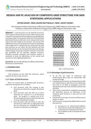
- 1. International Research Journal of Engineering and Technology (IRJET) e-ISSN: 2395-0056 Volume: 04 Issue: 08 | Aug -2017 www.irjet.net p-ISSN: 2395-0072 © 2017, IRJET | Impact Factor value: 5.181 | ISO 9001:2008 Certified Journal | Page 792 DESIGN AND FE ANALYSIS OF COMPOSITE GRID STRUCTURE FOR SKIN STIFFENING APPLICATIONS NITISH GHADI1, PROF.ANAND MATTIKALLI2, PROF. ANANT GHADI3. 1Post Graduate Student, Department of Mechanical Engineering, MMEC Belgaum, Karnataka, India 2,3Professors, Department of Mechanical Engineering, MMEC Belgaum, Karnataka, India ---------------------------------------------------------------------***--------------------------------------------------------------------- Abstract - A grid structures are the shell like structures, which supports the skin of any structure. When made up with composite materials Gridstructuresfindverygoodapplication in aerospace field. The properties of the skin can be uniformly distributed, thickness of the skin can be reduced which intern reduces the total weight of the structure. The present skin stiffened structures are having thick skin and itiscontributing more weight and it is taking some part of the load. By using grid structures we can reduce the skin thickness and load shared by the skin can be minimized which gives the damage tolerant design concept for aerospace structures and it also lays foundation for the futuristic adaptive structures. Therefore presently composite grid structure analysis is conducted to know the effectiveness of the various grid structures in skin stiffening applications Key Words: Intrinsicallystiff,flexural stiffness,Delimitation, Reinforced, Contamination 1. INTRODUCTION 1.1 Grid structures Grid structures are the shell like structures, which supports the skin of any structure. 1.1.1 Types of Grid Structures There are several types of standard grid structures. Important among them are as follows: Grid structures with ribs running in four directions are referred to as quadri-directional grids. Grid structures with ribs that are in three directions are referred to as tri-directional grids. An Iso-grid is a special case of tri- directional grid structurein whichtheribsform an array of equilateral triangles. Grid structures with ribs drawn in only two directions are referred to as angle grids and if the two directions are orthogonal then this structure is referred to as ortho-grid. Fig. 1.1 Grid structures 1.1.2 Advantages of grid structures As all ribs are made of continuous and unidirectional fibers, they are intrinsically stiff, strong and tough. Composite grid structuresaredamagetolerant.Ribs are unidirectional so that they do not delaminate and crack is not likely to propagate across the spacing between ribs or the interface between ribs and skins. There exists a potential for completely automating the fabrication process. So fabrication of the composite grid structures is easy and less time consuming. Grid structures are open structuresandthuseasyto inspect or repair. Grid structures are generally addedtoflatorcurved skin panels to Increase out – of – plane flexural stiffness. Resist flexural loads with additional cross sectional area to withstand axial loads. Act in addition as fins to dissipate heat and moisture.
- 2. International Research Journal of Engineering and Technology (IRJET) e-ISSN: 2395-0056 Volume: 04 Issue: 08 | Aug -2017 www.irjet.net p-ISSN: 2395-0072 © 2017, IRJET | Impact Factor value: 5.181 | ISO 9001:2008 Certified Journal | Page 793 1.1.3 Application of grid structures Grid structures are extensively used in aerospace, automobile and in civil structural applications. The grid structures consist of inherent resistance to impact damage, delimitation and crack propagation. Grid structure behavior study is inescapable, before implementation. Since the aerospace structures are subjected to combined loading situations, a proper study must be carried out for the grid structure model but not under single load case, but as multi- directional surface in failure space, which is termed as failure envelope. 1.2 Composite materials Composite materials are the materials that are made from two or more constituent materials with notably different physical or chemical properties,thatwhenmerged, produce a material with characteristicsthatisdifferentfrom the single components. The individual componentscontinue to exist separately and distinctly within the finished structure. The new material may be preferred for several reasons: commonly include materials which are stronger, lighter or inexpensive when compared to traditional materials. 1.2.1 Importance of composite materials The properties of compositematerialscannotbeachieved by the constituent materials alone. It is observed that composites are becoming extremely important asitcanhelp to improve the quality of our life. Composites are utilized in flight vehicles, automobiles, boats, pipelines, buildings, roads, bridges, and dozens of other products. Researchers are trying to find out ways to improve qualities of composites which would mean they may be strong, lightweight, long-lived, and inexpensive to produce. 1.2.2 Different types of composites Natural composites Producing composites is an attempt to replicate nature. Example wood is a composite of cellulose fibers that are cemented together with lignin. Man-made composites They are made by adding reinforcing fibers into polymer matrix, metal matrix or ceramic matrix respectively. o Polymer matrix composites (PMCs) o Metal matrix composites (MMCs) o Ceramic matrix composites (CMCs) o Carbon - Carbon Composite (CCC s) o Intermetallic Matrix Composites (IMCs) Polymer matrix composites (PMCs) The most common composites are the Polymer Matrix Composites (PMCs) that are also known as Fibre Reinforced Polymers (or Plastics) FRP. These substancesusea polymer- based resin as the matrix, and also a variety of fibres such as glass, carbon and aramid as the reinforcement.Thesematrix materials are thermosetting thermoplastic, rigid rod plastic, elastomer, and thermo elastic plastic polymers. The reinforcing fibres are continuous or chopped. In summary, polymer composites processing includes contracting of polymer and fibres, shaping, controlled heating and / or reactions, and cooling process. This technique of polymer composites has expanded its scope to larger extent in aerospace arid military applications. Metal matrix composites (MMCs) Metal matrix composites can be acquired using either a primary liquid phase approach like squeeze casting/infiltration or spray deposition, or a primary solid state processing such as powder techniques and foil diffusion. Common MMCs are aluminium based MMCs, fibre reinforced titanium alloys, and magnesium alloy-SiC particulate MMC. The aluminium-based materials are the most popular due to their cost and easy fabrication. Ceramic matrix composites (CMCs) Ceramic Matrix Composites (CMCs) are utilized in very high temperature environments. The definition of the ceramic matrix can be broader. It includes inorganic silica- based glass, crystalline ceramics, glass-ceramics, intermetallic and carbon. All of these have an unique unifying thread and they are fairly high temperature structural materials. In CMCs, the ceramic matrix covers a wide variety of inorganic materials, which are usually non- metallic and are processed in high temperatures. Common ceramic matrix materials include various glasses, glass ceramics and ceramics, such as carbon, silicon carbide, silicon nitride, aluminised and oxides. Thesereinforcements can include carbides, borides and oxides. Carbon - carbon composite (CCC s) The development of carbon-carbon materials began in early 1958 and was nurtured under the US Air Force space plan program DynaSoar,and NASA3ApolloprojectsCarbon- carbon materials are a generic class of composites like graphite /epoxy family of polymer matrix composites. They can be created in a wide variety of forms. From one dimensional to non-dimensional using unidirectional tow tapes or woven cloth. Because of their multiple formations, their mechanical properties can be readily tailored. Carbon materials have high strength and potential to stay stiff as well as high thermal and chemical stability in inert environment .They must however, be protected with coatings and /or surface sealants when used in an oxidizing environment.
- 3. International Research Journal of Engineering and Technology (IRJET) e-ISSN: 2395-0056 Volume: 04 Issue: 08 | Aug -2017 www.irjet.net p-ISSN: 2395-0072 © 2017, IRJET | Impact Factor value: 5.181 | ISO 9001:2008 Certified Journal | Page 794 Intermetallic Matrix Composites (IMCs) Several problemslimitthedevelopmentofinter-metallic- matrix composites (IMCs) in majority including chemical incompatibility and CTE mismatch between potential reinforcement of fibres and matrix materials, poor-to-low- temperature ductility, and marginally high-temperature oxidation resistance of intermetallic materials. Composite fabrication and joining processes do not result in excessive fibre/matrix reaction or matrix contamination. The beginning phase of the IMC program involves investigating available fibre compositions (SiCandAl203)in aluminisedof iron, titanium, nickel, and niobium. These aluminise are Ti3 AI and Fe3C for applications to 1000°C and NiAI and Nb- alloy/aluminised for higher temperature applications. The studies of alloying these materials are aimed at increasing toughness, ductility,andoxidationresistance,andpromoting long time stability with the candidate fibre materials. Candidate matrices will be evaluated using tensile, compression, fatigue, creep, and oxidation tests. Measuring appropriate thermal and physical properties is another planned task. Powder-cloth fabrication processeshavebeen developed to produce IMC materials, and alternative processing procedures, such as thermal spraying, are being Ti3Al + Nb material, based on tensile, thermal-cycle, and strain-controlled fatigue studies for temperatures up to 815°C. Studied Encouraging results have been obtained on SiC---reinforced. 1.3 Objectives of the present work In the present work orthogrid and isogrid concepts will be used for skin stiffening applications. In the first step of our project a rectangular panel or plate is designed with Orthogrid and isogrid skin stiffener for some desired load conditions with same skin thickness.Thedesigned platesare analyzed for deflection and stress using finite element analysis (FEA) software such asAnsys. Inthesecondstepthe skin thickness of ortho-grids is changed to get the same weight of both the plates. Conclusionswill bederived related to the deflection, stress distribution and stiffness to weight ratio of the designed structures. 2. ANALYSIS OF COMPOSITE PLATE 2.1 Introduction to Finite Element Analysis (FEA) The Finite Element Method (FEM) is a numerical procedure for getting approximate answers to many of the problems encountered in Engineering. In FEM the complete region is discretized in to a number of geometric shapes, which are called as elements. The governing relationships and the properties are assumed over there elements and expressed mathematically at specific pointswhicharecalled nodes. An assembly procedure is used to link individual elements and the effects of loading and boundaryconditions applied over these elements to get a set of relations either linear or nonlinear solutions to these equations would provide approximate solution of that particular system. The FEM originated in the design of aircrafts asa method of stress analysis. It started asanextensionofmatrixmethod of structural analysis. Today this FEM method is used not only for the analysis in solid mechanics, but even in the analysis of heat transfer, liquid flow, electric and magnetic field and civil engineering. This method is extensively used for the analysis of beams, space frames, plates, sheets etc. in aforementioned fields. This method is also used for critical and complicated analysis like the analysis and design of ships, aircrafts, space crafts, heat engines etc. Today the developments in main frame computer and availability of powerful microcomputer have brought this method within research of students and engineers working in small industries. 2.1.1 Steps involved in FEA The first step in finite element analysis is to model the given system. In this two distinct approaches to model physical systems, the discrete lumped approach and the continuum approach. In the former approach the factual system is initially idealized as an assembly of the elements and the equilibrium equations is given for each element and the result is used to set of equations is solved to yield the solutions. In the later approach these actual system is treated as one continuum and one or more equilibrium equations are written which are then solved for the system response. The given continuum after being divided into finite elements is called finite element model. A typical finite element model is comprised of nodes, elements material properties, degrees of freedom, boundary conditions, externally applied loads and analysis type. Engineers and designers must carefully create the model to ensure the relevance of the results of the corresponding FEA. These results depend solely on the model. In practice, practitioners mustdecideonthemeshlayout, i.e. the number of nodes and elements. Zones of expected abrupt changes in the unknown variables (such as stress concentration around holes) require a denser number of nodes and elements then zone where gradual changesoccur, this known as gradation. After the mesh layout is chosen practitioners must choose the analysis (static/dynamic, linear/nonlinear, beam, theory plane stress, three dimensional etc.) the type (deflection, rotation,temperature, flux etc.) and number of degrees offreedomateachnode, the boundary conditions, relevant information (type, numberof nodes per element etc.), material properties and dumping external loads at the nodes. There are many alternative to solve linear and nonlinear boundary and initial valueproblem,rangingfromcompletely numerical. Exact solutions are usually available for a few solutions usually with simple domains (e.g.regulardomain). This solution can be obtained by direct integration of the
- 4. International Research Journal of Engineering and Technology (IRJET) e-ISSN: 2395-0056 Volume: 04 Issue: 08 | Aug -2017 www.irjet.net p-ISSN: 2395-0072 © 2017, IRJET | Impact Factor value: 5.181 | ISO 9001:2008 Certified Journal | Page 795 differential equations. This can be achieved by techniques such as separation of the variables at Fourier and Laplace transformations to name only a few. Approximations are usually sought of approximate technique exist and include perturbations, power series probability scheme,themethod of weighted residuals the finite difference method, the Raleigh-Ritz method and the finite element method. Once the finite element model is defined by choosing all of the above parameter of the corresponding mesh, it must be input to the code that performs the FEA. A review of the most exciting FEA commercial codes reveals that require there user to provide the data of the finite model in a data of the finite model in a data file with specification detailed format of a certain data file, such a file usually has five major sections: control, nodal, element, material and loading sections. While later four sections are self-explanatory, the control section includes information such as the problem description (heading), the total number nodes, the type of analysis etc. These codes have the six modules. Node module: Node generates degree of freedom, and nodal co-ordinates. Boundary condition module: It stores material properties in the library of material. Element module: It various element types in an element library, evaluates element matrices and assemblies these matrices. Loading module: It applies the externallyappliedloads to the proper nodes and elements. Solution module: This module solves the system of equation that results from the assembly process of the element module for the unknown modules. FEA codes consist of pre-processors and post-processor. Pre-processors and post-processor are classified as much relative to FEA process. Pre-processing precedes this process and help the user to automate and/or facilitate the input required by the first modules described in the results in various graphical forms to get better understand and interpret them. The output from FEA codes is primarily in numerical form. It usually consists of the nodal values of the unknown variables and derivatives. For e.g.: In solid mechanics problems the output is the nodal temperatures and element stress, in heat transfer problems the output is the nodal temperatures and element heat fluxes.Graphical outputs are usually more informative in providing trends of continuum behavior. Thus curves and contours of the field variable can be plotted and displayed. Also deformed shapes can be displayed superposed on unreformed shapes. 2.1.2 Advantages of the FEA FEA method Can readily handle complex geometry: FEA method can handle complex analysis types such as: Vibration, Transients, Nonlinear, Heat transfer, Fluids etc. FEA method Can handle complex loading: Node based loading (point load), Element based loading (pressure, thermal, inertial forces), Time or frequency dependent loading. FEA method can handle complex restraints: Indeterminate structures can be analyzed. FEA method can handle bodies comprised of non-homogeneous materials: Every element in the model could be assigned a different set of material properties. FEA method Can handle bodies comprised of non-isotropic materials: Orthotropic, Anisotropic FEA method Special material effects are handled: Temperature dependent property, Plasticity, Creep, Swelling. 2.2 Composite plate analysis In the present work the composite plate with the following dimensions is considered for the FEA modeling and analysis. Dimensions of the plate: width = 500 mm, length = 700 mm, skin thickness = 3 mm The analysis has been carried out with two grid structures: ortho-grid and iso-grid and the results are compared in order to check that which grid structure enhances the stiffness properties of the skin. Finite element modeling As it is a composite material for plate modeling a structural element is used that is shell linear layer 99. Inthis element the thickness is built by using the number of layers of laminates. A 5 layered symmetric shell plates with bidirectional i.e. 0-90-0-90-0 laminates with each layer of thickness 0.5 mm is used to build the skin thicknessof3mm. Carbon- Epoxy composite material is considered in the present work. Carbon is isotropicmaterial andithasYoung’s Modulus of 39500 MPa and Poisson’s ratio 0.245. Then in the modeling part a plate of length 700 mm and width 500 mm is created. On that skin ortho grids and iso grids are generated in which ribs are placed orthogonal i.e. 900 and 600 to each other respectively. Then the area of skin is divided with reference to ribs and mapped meshing is done for each area of ribs and skin.
- 5. International Research Journal of Engineering and Technology (IRJET) e-ISSN: 2395-0056 Volume: 04 Issue: 08 | Aug -2017 www.irjet.net p-ISSN: 2395-0072 © 2017, IRJET | Impact Factor value: 5.181 | ISO 9001:2008 Certified Journal | Page 796 Material properties Material = Carbon/epoxy composite material Transverse tensile strength of carbon/epoxy = 600 MPa Longitudinal compressive strength of carbon/epoxy = 570 MPa Density = 1.6 X 10⁻⁶ Kg / mm3 (Reference - http://www.azom.com/article.aspx) 2.2.1 Skin with ortho-grid For the present analysis ortho-grids structure rib thickness and rib depth are taken as 3 mm and 25 mm respectively. Skin thickness is taken as 3 mm. Fig.2.1 Meshed model of the composite plate with ortho- grid Load Case 1: Two ends fixed with transverse loading boundary conditions Two opposite ends that are of length 500 mm are fixedanda transverse load of 100 KN is applied on the skin. Now the uniform pressure that is to be applied on the skin is given by Eq. (2.1). P F A (2.1) 3 100 10 700 500P 0.285MPaP This magnitude of pressure is applied on the skin. Fig. 2.2 Two ends fixed with transverse load (deflection) Result After the analysis it is found that the maximum deflection is at the center of the plate and its magnitude is 33.897 mm. Fig. 2.3 Two ends fixed with transverse load (Stress) Result After the analysis a maximum stress of 915.547 N/mm² is observed at the center of the plate. Near the fixed ends the stress development is minimum. Load Case 2: One ends fixed axial loading boundary conditions One end of length 500mm is fixed and axial load of 1000 N is applied on the ribs on opposite side.
- 6. International Research Journal of Engineering and Technology (IRJET) e-ISSN: 2395-0056 Volume: 04 Issue: 08 | Aug -2017 www.irjet.net p-ISSN: 2395-0072 © 2017, IRJET | Impact Factor value: 5.181 | ISO 9001:2008 Certified Journal | Page 797 1000 500*25P 0.08MPaP This magnitude of pressure is applied on the skin Fig. 2.4 one ends fixed axial loading (deflection) Result After the analysis a maximum deflection of 9.134 mm is observed at the free end of the plate. Fig. 2.5 One end fixed axial load (Stress) Result After the analysis a compressive stress of 214. 298 N / mm2 is induced at the fixed end of the plate and at the lower side of the rib. Towards free end the stress is minimum and its magnitude is 45.288 N / mm2. 2.2.2 Skin with Iso-Grid The rib dimensions for the ortho-grids are: thickness = 3 mm, depth = 25 mm and the skin thickness is 3 mm. Fig.2.6 Meshed model of the composite plate with iso-grid Load Case 1: Two ends fixed with transverse loading boundary conditions Two opposite ends that are of length 500 mm are fixed and transverse load of 100 KN is applied on the skin. 3 100 10 700 500P 0.285MPaP This magnitude of pressure is applied on the skin. Fig. 2.7 Two ends fixed with transverse load (deflection)
- 7. International Research Journal of Engineering and Technology (IRJET) e-ISSN: 2395-0056 Volume: 04 Issue: 08 | Aug -2017 www.irjet.net p-ISSN: 2395-0072 © 2017, IRJET | Impact Factor value: 5.181 | ISO 9001:2008 Certified Journal | Page 798 Result After the analysis it is found thatthemaximumdeflection is at the center of the plate and its magnitude is 23.177 mm. Fig. 2.8 Two ends fixed with transverse load (Stress) Result After the analysis a maximum stress of 663.352 N/mm² is observed at the center of the plate. Near the fixed ends the stress development is minimum. Load Case 2: One ends fixed axial loading boundary conditions One end of length 500mm is fixed. Axial load of 1000 N is applied on the ribs on opposite side. 1000 500*25P 0.08MPaP This amount of pressure is applied on the skin. Fig. 2.9 one ends fixed axial loading (deflection) Result After the analysis a maximum deflection of 6.965 mm is observed at the free end of the plate. Fig. 2.10 One end fixed axial load (Stress) Result After the analysis a compressivestressof73.622N /mm2 is induced at the fixed end of the plate and at the top side of the rib. Towards free end the stress is minimum and its magnitude is 28.963 N / mm2. Reduced thickness of Iso-grid plate Now for the same amount of load the skin and rib dimensions for the Iso-grids structure are reduced to 2.22 mm and the analysis is carried out. Load Case 1: Two ends fixed with transverse loading boundary conditions Fig. 2.11 Two ends fixed with transverse load (deflection)
- 8. International Research Journal of Engineering and Technology (IRJET) e-ISSN: 2395-0056 Volume: 04 Issue: 08 | Aug -2017 www.irjet.net p-ISSN: 2395-0072 © 2017, IRJET | Impact Factor value: 5.181 | ISO 9001:2008 Certified Journal | Page 799 Result After the analysis it is found thatthemaximumdeflection is at the center of the plate and its magnitude is 31.422 mm. Fig. 2.12 Two ends fixed with transverse load (Stress) Result After the analysis a maximum stress of 892.226 N/mm² is observed at the center of the plate. Near the fixed ends the stress development is minimum. Load Case 2: One ends fixed axial loading boundary conditions One end of length 500mm is fixed and axial load of 1000 N is applied on the ribs on opposite side. Fig. 2.13 one ends fixed axial loading (deflection) Result After the analysis a maximum deflection of 9.465 mm is observed at the free end of the plate. Fig. 2.14 One end fixed axial load (Stress) Result After the analysis a compressive stress of 98.23 N / mm2 is induced at the fixed end of the plate and at the top side of the rib. Towards free end the stress is minimum and its magnitude is 39.14 N / mm2. 2.2.3 Analytical calculation Stiffness (k) For both the plates Transverse load = 100 KN and Axial load = 1000N For Transverse load Ortho grid, Stiffness = Force / Displacement k= 100e3 / 33.897 k = 2950.11 N/mm Iso grid, Stiffness = Force / Displacement k= 100e3 / 23.177 k =4314.62 N/mm For Axial load Ortho grid,
- 9. International Research Journal of Engineering and Technology (IRJET) e-ISSN: 2395-0056 Volume: 04 Issue: 08 | Aug -2017 www.irjet.net p-ISSN: 2395-0072 © 2017, IRJET | Impact Factor value: 5.181 | ISO 9001:2008 Certified Journal | Page 800 Stiffness = Force / Displacement k= 1000 / 9.134 k = 109.48 N/mm Iso grid, Stiffness = Force / Displacement k= 1000 / 6.96 k = 143.678 N/mm Weight (W) Weight = Mass * Acceleration of Gravity But Mass = Density * Volume For Ortho Grid Volume V = Volume of Plate + Volume of Ribs V= (700*500*3 ) + ( ( 700*3*25 )*6 + ( 500*3*25 )*8) V = 1612500 mm3 Mass M = 1.6*e-6 * 1612500 M = 2.58 Kg W = 2.58 * 9.81 W = 25.30 N For Iso-Grid Volume V = Volume of Plate + Volume of Ribs V= (700*500*2.22) + [ (700*2.22*25)*6 + (500*2.22*25)*2 +( 70*2.22*25)*140 V = 1609500 mm3 Mass M = 1.6*e-6 * 1609500 M = 2.57 Kg W = 2.57 * 9.81 W = 25.27 N Reduced thickness of Iso-grid structure Stiffness (k) For both the plates Transverse load = 100 KN and Axial load = 1000N For Transverse load Iso grid, Stiffness = Force / Displacement k= 100e3 / 31.42 k = 3182.48 N/mm For Axial load Iso grid, Stiffness = Force / Displacement k= 1000 / 9.46 k = 105.70 N/mm Weight (W) Weight = Mass * Acceleration of Gravity Mass = Density * Volume Volume V = Volume of Plate + Volume of Ribs = (700*500*2.23) + (700*2.23*25)*6 + (500*2.23*25)*2 + (70*2.23*25)*140 V = 1616750 mm3 Mass M = 1.6*e-6 * 1616750 M = 2.58 kg W = 2.58 * 9.81 W = 25.31 N 3. CONCLUSIONS In the present work the effect of orth-gridandiso-gridon the composite skin structure is studied through finite element analysis. Results derived from the analysis are tabulated below and the conclusions made fromtheanalysis are also discussed. Table 5.1 Analysis results for same skin thickness Boundary Conditions Ortho - grid structure Iso - grid structure % Error 1.Weight 25.30 N 34.14 N 34.94 2.Two end fixed Transverse load Deflection 33.897 mm 23.177 mm 46.25 Stress 915.547 N/mm² 663.352 N/mm² 38.01 Stiffness 2950.11 N/mm 4314.6 N/mm 46.25
- 10. International Research Journal of Engineering and Technology (IRJET) e-ISSN: 2395-0056 Volume: 04 Issue: 08 | Aug -2017 www.irjet.net p-ISSN: 2395-0072 © 2017, IRJET | Impact Factor value: 5.181 | ISO 9001:2008 Certified Journal | Page 801 3.One end fixed axial load Deflection 9.134 mm 6.96 mm 31.23 Stress 45.288 N/mm² 28.963 N/mm² 56.36 Stiffness 109.48 N/mm 143.678 N/mm 31.23 Table 5.2 Analysis results for reduced skin thickness of iso-grid Boundary Conditions Ortho - grid structure Iso - grid structure % Error 1.Weight 25.30 N 25.30 N 0.0 2.Two end fixed Transverse load Deflection 33.897 mm 31.422 mm 7.87 Stress 915.547 N/mm² 892.226 N/mm² 2.61 Stiffness 2950.11 N/mm 3182.48 N/mm 7.87 3.One end fixed axial load Deflection 9.134 mm 9.46 mm 3.56 Stress 45.288 N/mm² 39.14 N/mm² 15.70 Stiffness 109.48 N/mm 105.70 N/mm 3.57 From the above results it can be observed that for the same skin thickness under transverse loading deflection in the iso-grid structure is 37% less than the orth-grid. Structural stiffness is enhanced by 46.25% in iso-grid. Also the maximum stress induced in the iso-grid plate is 38% lower than the ortho-grid plate. For the axial loadingtheiso- grid structure provides 31.23% higher stiffness than the ortho-grid. However the weightofiso-gridstructureisfound to be 35% higher than the ortho-grid structure. Therefore to reduce the weight of the iso-grid structure the ribs and skin thickness is reduced by 26%. Now the weight of iso-grid plate is same as that of orth-grid plate. Analysis is carried out again to check the performance of the iso-grid platewith reduced weight. In this case also theiso-gridsperform better than the ortho-grids in transverse load condition. However in axial loading case the stiffness of theiso-gridisreduced by 3.4 %. This is because the cross sectional area in the axial loading is more for ortho-grid compared to iso-grid. However this difference is minimum because the diagonal members of iso-grid structure have also contributed to support the axial load. So finally it can be conclude that iso-grid structures are better than ortho-grid in skin stiffening applications. ACKNOWLEDGEMENT It gives us an immense pleasure to acknowledge all the people who helped us in successful completion of this project. We take this opportunity to express our most sincere gratitude and profound regards to our beloved Principal Prof. V.R.UDUPI for providing all the facilities to do this Project. Also we express our deep sense of gratitude and appreciation to our beloved H.O.D. Prof. S. S.MASHYAL for this enthusiastic inspiration in all phases of our Project. With due respects we would like to express our sincere thanks to our Project GuideProf. A. C.MATTIKALLIfor his sterling efforts and timely guidance, patience in solving our doubts, which kept cropping up in due course of our project work needs special credits. Our sincere thanks to all the people who have contributed to complete this Project successfully. REFERENCES 1. Knou H., Nabavi S.M., Jam J.E., 2005. “Modeling and analysis of composite grid structure.” 2. Adam B., Higgins J., 2007. “Design and evaluation of reinforced advanced grid stiffened composite structure.” 3. Blom A. W., Russian M., Stickler P. B., 2010. “Bending test of variable stiffness fiber reinforced composite cylinder.” 4. Al-Mosawi A. I., Al-Maamori M. H., Wetwet Z.A., 2012. “Mechanical propertiesofcompositematerial reinforcing by natural synthetic fibre.” 5. Arashamehr J., Rahimi G.H., Rasouli S. F., 2013. “Experimental and numerical study of a stiffened composite cylindrical cell with clamped free boundary conditionsundertransverseendloading.” 6. Mukhopadhyay M., 2009. “Mechanics of composite materials and Structures.” 7. Das J.B.K., 8th edition 2013. “Design of Machine Elements-1.” 8. Lingaiah K., 2006. “Design Data Handbook.” 9. Mikulas M. M., 1978. “Iso-grid Design Handbook.” 10. Swamy A.R.K., “Finite Element Method.”
- 11. International Research Journal of Engineering and Technology (IRJET) e-ISSN: 2395-0056 Volume: 04 Issue: 08 | Aug -2017 www.irjet.net p-ISSN: 2395-0072 © 2017, IRJET | Impact Factor value: 5.181 | ISO 9001:2008 Certified Journal | Page 802 BIOGRAPHIES Mr.Nitish Ghadi post graduate studentof the Dept. of Mechanical Engg, Maratha Mandal Engineering College Belgaum. Area of Interest in machine design, Manufacturing Tech. Mr.Anand Mattikali is a faculty member in the Dept. of Mechanical Engg, Maratha Mandal Engineering College, Belgaum. His areas of interest include machine design, Manufacturing Tech. Mr. Anant J. Ghadi is a faculty member in the Dept. of Mechanical Engineering, Maratha Mandal Engineering College, Belgaum. His areas of interest include machine design, manufacturing technology and its applications to agriculture.