SlideShare a Scribd company logo
1 of 8
Download to read offline
IJRET: International Journal of Research in Engineering and Technology eISSN: 2319-1163 | pISSN: 2321-7308
__________________________________________________________________________________________
Volume: 03 Special Issue: 03 | May-2014 | NCRIET-2014, Available @ http://www.ijret.org 738
DESIGN AND ANALYSIS OF COMPOSITE DRIVE SHAFT
V. S. BHAJANTRI1
, S. C. BAJANTRI2
, A. M. SHINDOLKAR3
, S. S. AMARAPURE4
1
Assistant Professor, Dept. Of Mech. Engg., SCET, Belgaum-591156
2
Assistant Professor, Dept. Of Mech. Engg., SCET, Belgaum-591156
3
Assistant Professor, Dept. Of Mech. Engg., SCET, Belgaum-591156
4
Assistant Professor, Dept. Of Mech. Engg., SCET, Belgaum-591156
Abstract
Substituting composite structures for conventional metallic structures has much advantage because of higher specific stiffness and
strength of composite materials. This work deals with replacement of conventional two piece steel drive shaft with a single-piece e-
glass/epoxy, high strength carbon/epoxy and high modulus carbon/epoxy composite drive shaft for automobile shaft for an automotive
application. The design parameters were optimized with the objective on minimizing the weight of composite drive shaft.
-----------------------------------------------------------------------***----------------------------------------------------------------------
1. INTRODUCTION
Composite materials have been widely used to improve the
performance of various types of structures. Compared to
conventional materials, the main advantages of composites are
their superior stiffness to mass ratio as well as high strength to
weight ratio. Because of these advantages, composites have been
increasingly incorporated in structural components in various
industrial fields. Some examples are helicopter rotor blades,
aircraft wings in aerospace engineering, and bridge structures in
civil engineering applications. Some of the basic concepts of
composite materials are discussed in the following section to
better acquaint ourselves with the behaviour of composites.
1.1 Basic Concepts of Composite Materials
Composite materials are basically hybrid materials formed of
multiple materials in order to utilize their individual structural
advantages in a single structural material. The constituents are
combined at a macroscopic level and are not soluble in each
other. The key is the macroscopic examination of a material
wherein the components can be identified by the naked eye.
Different materials can be combined on a microscopic scale, such
as in alloying of metals, but the resulting material is, for all
practical purposes, macroscopically homogeneous, i.e. the
components cannot be distinguished by the naked eye and
essentially acts together. The advantage of composite materials is
that, if well designed, they usually exhibit the best qualities of
their components or constituents and often some qualities that
neither constituent possesses. Some of the properties that can be
improved by forming a composite material are strength, fatigue
life, stiffness, temperature-dependent behaviour, corrosion
resistance, thermal insulation, wear resistance, thermal
conductivity, attractiveness, acoustical insulation and weight.
Naturally, not all of these properties are improved at the same
time nor is there usually any requirement to do so. In fact, some
of the properties are in conflict with one another, e.g., thermal
insulation versus thermal conductivity. The objective is merely to
create a material that has only the characteristics needed to
perform the designed task.
There are two building blocks that constitute the structure of
composite materials. One constituent is called the reinforcing
phase and the one in which it is embedded is called the matrix.
The reinforcing phase material may be in the form of fibres,
particulates, flakes. The matrix phase materials are generally
continuous. Examples of composite systems include concrete
reinforced with steel, epoxy reinforced with graphite fibres, etc
1.2 Fibres
Fibres are the principal constituent in a fibre-reinforced
composite material. They occupy the largest volume fraction in a
composite laminate and share the major portion of the load acting
on a composite structure. Proper selection of the type, amount
and orientation of fibres is very important, because it influences
the following characteristics of a composite laminate.
a. Specific gravity
b. Tensile strength and modulus
c. Compressive strength and modulus
d. Fatigue strength and fatigue failure
mechanisms
e. Electric and thermal conductivities
f. Cost
The various types of fibres currently in use are
a. Glass Fibres
b. Carbon Fibres
c. Aramid Fibres
d. Boron Fibres
e. Silicon Carbide Fibres
1.3 Matrix
In a composite material the fibres are surrounded by a thin layer
of matrix material that holds the fibres permanently in the desired
IJRET: International Journal of Research in Engineering and Technology eISSN: 2319-1163 | pISSN: 2321-7308
__________________________________________________________________________________________
Volume: 03 Special Issue: 03 | May-2014 | NCRIET-2014, Available @ http://www.ijret.org 739
orientation and distributes an applied load among all the fibres.
The matrix also plays a strong role in determining the
environmental stability of the composite article as well as
mechanical factors such as toughness and shear strength.
The matrix binds the fibres together, holding them aligned in the
important stressed directions. The matrix must also isolate the
fibres from each other so that they can act as separate entities.
The matrix should protect the reinforcing filaments from
mechanical damage (e.g. abrasion) and from environmental
attack. A ductile matrix will provide a means of slowing down or
stopping cracks that might have originated at broken fibres;
conversely, a brittle matrix may depend upon the fibres to act as
matrix crack stoppers. Through the quality of its “grip” on the
fibres (the interfacial bond strength), the matrix can also be an
important means of increasing the toughness of the composite.
Because the reinforcing fibres can be oriented during fabrication
of item, composites can be tailored to meet increased load
demands in specific directions. The combined fibre-matrix
system is an engineered material designed to maximize
mechanical and environmental performance.
1.4 Classification of Composites
Composite materials in general are categorised based on the kind
of reinforcements or the surrounding matrix. There are four
commonly accepted types of composite materials based on
reinforcements-
a. Fibrous composite materials that consist of fibres in
a matrix.
b. Laminated composite materials that consist of
layers of various materials.
c. Particulate composite materials that are composed
of particles in a matrix.
d. Combinations of some or all of the first three types.
And the major composite classes based on structural composition
of the matrix are-
a. Polymer-Matrix Composites
b. Metal- Matrix Composites
c. Ceramic- Matrix Composites
d. Carbon- Carbon Composites
e. Hybrid Composites
1.5 Applications of Composite Materials
The common applications of composites are extending day by
day. Nowadays they are used in medical applications too. Some
other fields of applications are,
 Automotive : Drive shafts, clutch plates, fibre
Glass/Epoxy leaf springs for heavy trucks and trailers,
rocker arm covers, suspension arms and bearings for
steering system, bumpers, body panels and doors.
 Aerospace: Drive shafts, rudders, elevators, bearings,
landing gear doors, panels and floorings of airplanes,
payload bay doors, remote manipulator arm, high gain
antenna, antenna ribs and struts etc.
 Marine: Propeller vanes, fans & blowers, gear cases,
valves &strainers, condenser shells.
 Chemical Industries: Composite vessels for liquid
natural gas for alternative fuel vehicle, racked bottles for
fire service, mountain climbing, underground storage
tanks, ducts and stacks etc.
 Electrical & Electronics: Structures for overhead
transmission lines for railways, Power line insulators,
Lighting poles, Fibre optics tensile members etc.
1.6 Drive Shaft
As mentioned above, recent developments in the applications of
composite materials have shown that a composite material
structural member used in power transmission can be of a great
assistance in overcoming a few of the problems faced with
conventional drive shafts. The assessment of the extent of this
fact is the essence of this work. Therefore a good understanding
of the drive shaft would be a prerequisite and is discussed in the
following section.
A drive shaft, propeller shaft (prop shaft), or Cardan shaft is a
mechanical component for transmitting torque and rotation,
usually used to connect other components of a drive train that
cannot be connected directly because of distance or the need to
allow for relative movement between them. Drive shafts are
carriers of torque. They are subject to torsion and shear stress,
equivalent to the difference between the input torque and the
load. They must therefore be strong enough to bear the stress,
whilst avoiding too much additional weight as that would in turn
increase their inertia. Therefore a drive shaft is expected to
function, as follows.
a. It must transmit torque from the transmission to the
differential gear box.
b. The drive shaft must also be capable of rotating at
very high speeds as required by the vehicle.
c. The drive shaft must also operate through constantly
changing angles between the transmission, the
differential and the axels.
d. The length of the drive shaft must also be capable of
changing while transmitting torque.
Thus the design of a drive shaft presents itself as a case of torsion
problem. Further, with regard to the conventional drive shafts
following shortcomings were observed some of which could be
addressed better with a composite shaft.
1. They have less specific modulus and strength
2. Increased weight
3. Conventional steel drive shafts are usually
manufactured in two pieces to increase the
fundamental bending natural frequency because the
bending natural frequency of a shaft is inversely
proportional to the square of beam length and
proportional to the square root of specific modulus.
IJRET: International Journal of Research in Engineering and Technology eISSN: 2319-1163 | pISSN: 2321-7308
__________________________________________________________________________________________
Volume: 03 Special Issue: 03 | May-2014 | NCRIET-2014, Available @ http://www.ijret.org 740
Therefore the steel drive shaft is made in two sections
connected by a support structure, bearings and U-
joints and hence overall weight of assembly will be
more.
4. Its corrosion resistance is less as compared with
composite materials.
5. Steel drive shafts have less damping capacity.
Since a drive shaft is a case of torsion problem an understanding
of the methodology of solving such a problem in structural
mechanics is necessary.
1.7 Torsion Problem in Structural Mechanics
Torsion of cylindrical shafts has long been a subject of interest in
power transmission problems. To this end the stiffness of a
cylindrical shaft under torsional loading is considered. The axial
displacement field of the cross-section is assumed not to vary
along the axial direction away from the ends of the shaft. Under
this assumption, the torsional rigidity is only dependent on the
shape of the cross-section. The governing equations of this
boundary value problem can be formulated in terms of a Laplace
or Poisson Equation. Within the former one, one uses the
warping function as dependent variable, while in the latter the
Prandtl’s stress function is used. The solutions for the warping
and Prandtl’s stress function have been obtained exactly for
simple cross-sectional shapes such as a circle, annulus, ellipse,
rectangle, and triangle. For more complicated shapes, numerical
methods are usually employed, such as, the finite difference
method, finite element method and boundary element method.
Some authors use the approach of combination of experimental
and analytical methods to predict the effective in-plane and out-
of-plane shear moduli of structural composite laminates. Due to
the extensive use of composite materials, the study of compound
bars under torsion has become a point of focus in the recent days.
1.8 Torsion of Composite Shafts
Compared to homogeneous cylindrical shafts, the torsional
behaviour of composite shafts is considerably more complicated.
The torsional rigidity not only depends on the global cross-
sectional geometry, but also on the properties and configurations
of each constituent. The analytical solution of compound bars
under torsion was first obtained by Muskhelishvili (1963), where
the solution was expressed in terms of eigen functions.
Packhamand Shail (1978) used linear combinations of solutions
of a homogeneous shaft to solve the problem in which the cross
section is symmetric with respect to the common boundary. The
elastic properties of non-homogeneous anisotropic beams are
usually of engineering interest. Torsional rigidities of
multilayered composite beams are especially needed when
structures are under torsional loading. Savoia and Tullini (1993)
analyzed the torsional response of composite beams of arbitrary
cross section. The boundary value problem was formulated in
terms of both warping and Prandtl’s stress function. Using the
eigen function expansion method, the exact solution of
rectangular multilayered orthotropic beams under uniform
torsion was derived. Swanson (1998) extended the existing
solutions of torsion of orthotropic laminated rectangular beams to
the high aspect ratio case. Based on the membrane analogy, an
approximate solution of general, thin, laminated, open cross
sections was derived.
In this study, an analytical approach is proposed to solve the
torsion problem of laminated composite shafts that consist of
orthotropic sublaminates. The present approach uses the concept
of elastic constants (Chou, et al., 1972), in which the three-
dimensional nonhomogeneous orthotropic laminate is replaced
by an equivalent homogeneous orthotropic material. A small
element consisting of n layers from the composite material,
[assumed to represent the behaviour of the overall composite
laminate] is considered to be under a uniform state of stress when
the composite laminate is under arbitrary loading. Two
assumptions have been made in this regard: first, the normal
strains and shear strains parallel to the plane of layers are
uniform and the same for each constituent and the corresponding
stresses are averaged. Second, the normal stresses and shear
stresses perpendicular to the plane of layers are uniform and
equal for each constituent and the corresponding strains are
averaged. Under these two assumptions, the equilibrium at each
sublaminate interface and compatibility conditions of materials
are satisfied automatically. As the thickness of each layer
approaches zero, the overall effective elastic constants are
developed. The effective shear moduli of the composite
laminates are used to calculate the overall torsional rigidity of the
orthotropic laminated shaft.
Having convinced ourselves about the nature of the problem and
the possible solution to it, we now move on to develop a better
understanding of the fundamentals necessary for the present
work. A qualitative literature survey would greatly help us
achieve it and is presented in the following chapter.
1.9 Analysis of Composite Drive Shaft
A good design solution can be delivered only when the function
of the component being designed, is known before hand with
proper working condition specifications. Ability of different
methodologies in solving for these conditions can be appreciated
based on the complexity of the problem, though. Presently, the
specifications of the composite shaft to be designed are
considered to be same as that of an optimally designed steel
shaft. Comparison is made between the composite and the
conventional steel shaft for maximum shear stress induced in the
shafts and maximum deflections in the shafts. Finally modal
analysis is carried out to study the variation in natural frequency
by changing the fibre angle orientation of different layer of the
composite shaft.
1.9.1 Specification of Composite Shaft
In the present analysis hollow composite shaft is modelled in
ANSYS by using shell element and having following
specifications-
IJRET: International Journal of Research in Engineering and Technology eISSN: 2319-1163 | pISSN: 2321-7308
__________________________________________________________________________________________
Volume: 03 Special Issue: 03 | May-2014 | NCRIET-2014, Available @ http://www.ijret.org 741
a) Length of shaft L = 1 m
b) Outer radius of the shaft Ro = 50 mm with 5 mm thickness.
c) Torque applied at free end of shaft
1.9.2 Assumptions
In the analysis of the composite drive shaft following
assumptions are made.
1. The shaft rotates at a constant speed about its longitudinal
axis.
2. The shaft has a uniform, circular cross section.
3. The shaft is perfectly balanced, i.e., at every cross
section, the mass centre coincides with the geometric
centre.
4. All damping and nonlinear effects are excluded.
5. The stresses-strain relationship for composite material
is linear and elastic, i.e., Hooke’s law is applicable for
composite materials.
6. Acoustical fluid interactions are neglected, i.e., the shaft
is assumed to be acting in a vacuum.
7. Since lamina is thin and no out-of-plane loads are
applied, it is considered to be in plane stress condition.
1.9.3 Selection of Cross-Section
The shaft can be solid circular or hollow circular. Here hollow
circular cross-section was chosen because:
i. The hollow circular shafts are stronger in per kg weight
than solid circular shafts.
ii. The stress distribution in case of solid shaft is zero at the
centre and maximum at the outer surface while in hollow
shaft stress variation is smaller. In solid shafts the
material close to the centre are not fully utilized.
1.9.4 Selection of Reinforcement Fibre
Fibres are available with widely differing properties. Review of
the design and performance requirements usually dictate the fibre
to be used. So in our analysis we will consider the Carbon fibres
because its advantages include high specific strength and
modulus, low coefficient of thermal expansion, and high fatigue
strength which is ideal fibre for torque transmitting shaft.
1.9.5 Selection of Resin System
The important considerations in selecting resin are cost,
temperature capability, elongation to failure and resistance to
impact (a function of modulus of elongation). The resins selected
for most of the drive shafts are either epoxies or vinyl esters.
Here, epoxy resin was selected due to its high strength, good
wetting of fibres, lower curing shrinkage, and better dimensional
stability.
1.9.6 Why Carbon Epoxy Composite?
Following are the features of carbon epoxy composite, the reason
for which it is chosen.
1. Carbon epoxy composite gives high tensile strength,
high modulus of rigidity as compared to other
composites.
2. Carbon epoxy composite has unique damping
characteristic.
3. Carbon epoxy composite has positive coefficient of
thermal expansion i.e. tensile strength of this composite
increases with temperature.
4. Carbon epoxy composite is fatigue, wear and corrosion
resistant.
1.9.7 Selection of Material
Based on the advantages discussed above, the high strength and
high modulus Carbon/Epoxy materials are selected for composite
drive shaft. The Table 5.1 shows the properties of the
Carbon/Epoxy material used for composite drive shaft.
1.9.8 Modal Analysis of Composite Shaft
Modal analysis is used to determine the vibration characteristics
such as natural frequencies and mode shapes of a structure or a
machine component while it is being designed. A modal analysis
can be performed using the ANSYS. The vibration problem is
described by a set of equations, and there is a natural vibration
mode for every equation that can be extracted by using an Eigen
value extraction analysis. The displacement behaviour
dominating any structure subject to vibration is global; therefore,
modal analysis is utilized in these types of problems. In modal
analysis, the model of the composite shaft does not need a fine
mesh because the stress output is not required.
Additionally, there is no requirement to input an applied load,
because the natural frequency is only a function of mass and
stiffness. The ends of the composite shaft model were modelled
as simply-supported, and the boundary condition was varied until
the value of the natural frequency became nearly coincident with
that presented by a reliable example. It was recognized that the
end support conditions must also be applied to the edges of the
composite shaft. The rotational speed is limited by lateral
stability considerations. Most designs are sub critical, i.e.
rotational speed must be lower than the first natural bending
frequency of the shaft. The natural frequency depends on the
diameter of the shaft, thickness of the hollow shaft, specific
stiffness and the length. Boundary conditions for the modal
analysis are shown in Fig 5.3 below
IJRET: International Journal of Research in Engineering and Technology eISSN: 2319-1163 | pISSN: 2321-7308
__________________________________________________________________________________________
Volume: 03 Special Issue: 03 | May-2014 | NCRIET-2014, Available @ http://www.ijret.org 742
1.9.9 Modelling of Conventional Steel Shaft
Conventional drive shaft is made up of steel for most of the
automobile, but sometimes aluminium is also used. To compare
the capability of composite material, steel shaft strength is
compared with composite.
In present analysis conventional shaft is modelled in ANSYS and
its length is considered as 1 m and diameter of the shaft as 50
mm with 2.032 mm thickness. Similar dimensions are used in
composite shaft analysis. Steel material has young’s modulus of
Ex = 210 GPa and Poisson ratio equal to 0.3. Comparison is
carried out based on maximum deformation, maximum stresses
induced in the shaft. Table 5.2 below shows the properties of
steel.
Table 2 Properties of steel
Steel
E = 207 e 9 N/m2
µ = 0.3
G = 80 e 9 N/m2
Density = 7600 Kg/m3
Max. Torque Tmax= 3000 N-m
Now for the steel shaft the maximum stresses and maximum
deflections are found out first and then modal analysis is done.
Analysis procedure for steel shaft is the same as that for
composite shaft. The only exception being the homogeneous,
isotropic nature input, meaning the same value input for all
directions.
In the chapter that follows are presented the discussions about the
results obtained from the above analysis, for various orientations
and different layers of the composite shaft and for the steel shaft.
2. RESULTS AND DISCUSSIONS
2.1 Static Analysis
The maximum shear stress and maximum deflection for each
layer are obtained using ANSYS by varying the orientation of
fibre in that layer by 100
and keeping the orientation of other
layers constant i.e. 00
.
2.2 Variation of Stresses with Fibre Angle Orientation
of Different Layers
2.2.1 Layer 1
Table 3 Variations in stresses by changing fibre angle orientation
of layer 1
Configuration Layer 1 Layer 2 Layer 3 Layer 4
10/0/0/0 4.79E+06 2.98E+06 6.49E+06 3.25E+06
20/0/0/0 7.39E+06 2.86E+06 6.29E+06 3.20E+06
30/0/0/0 9.18E+06 2.74E+06 6.07E+06 3.16E+06
40/0/0/0 9.84E+06 2.68E+06 6.00E+06 3.13E+06
50/0/0/0 9.42E+06 2.71E+06 6.08E+06 3.19E+06
60/0/0/0 8.11E+06 2.80E+06 6.24E+06 3.23E+06
70/0/0/0 6.20E+06 2.91E+06 6.41E+06 3.26E+06
80/0/0/0 4.13E+06 2.99E+06 6.54E+06 3.27E+06
90/0/0/0 3.01E+06 3.02E+06 6.58E+06 3.28E+06
Fig 2 Variations in stresses by changing fibre angle orientation of
layer 1
Fig. 1 Boundary conditions for the
modal analysis for composite shaft
IJRET: International Journal of Research in Engineering and Technology eISSN: 2319-1163 | pISSN: 2321-7308
__________________________________________________________________________________________
Volume: 03 Special Issue: 03 | May-2014 | NCRIET-2014, Available @ http://www.ijret.org 743
2.2.2 Layer 2
Table 4 Variations in stresses by changing fibre angle orientation
of layer
Configuration Layer1 Layer2 Layer3 Layer4
0/10/0/0 2.97E+06 4.80E+06 6.48E+06 3.24E+06
0/20/0/0 2.85E+06 7.37E+06 6.29E+06 3.17E+06
0/30/0/0 2.73E+06 9.12E+06 6.04E+06 3.11E+06
0/40/0/0 2.67E+06 9.74E+06 5.95E+06 3.10E+06
0/50/0/0 2.70E+06 9.30E+06 6.02E+06 3.13E+06
0/60/0/0 2.79E+06 8.01E+06 6.19E+06 3.18E+06
0/70/0/0 2.90E+06 6.13E+06 6.38E+06 3.23E+06
0/80/0/0 2.98E+06 4.11E+06 6.53E+06 3.26E+06
0/90/0/0 3.01E+06 3.02E+06 6.58E+06 3.27E+06
Fig 3 Variations in stresses by changing fibre angle orientation of
layer 2
2.2.3 Layer 3
Table 5 Variations in stresses by changing fibre angle orientation
of layer 3
Fig 4 Variations in stresses by changing fibre angle orientation of
layer 3
2.2.4 Layer 4
Table 6 Variations in stresses by changing fibre angle orientation
of layer 4
Configurat
ion deflection1
Deflection
2 Deflection3 Deflection4
10/0/0/0 2.82E-04 2.82E-04 2.82E-04 2.82E-04
20/0/0/0 2.71E-04 2.71E-04 2.71E-04 2.71E-04
30/0/0/0 2.60E-04 2.60E-04 2.60E-04 2.60E-04
40/0/0/0 2.54E-04 2.54E-04 2.54E-04 2.54E-04
50/0/0/0 2.57E-04 2.57E-04 2.57E-04 2.57E-04
60/0/0/0 2.66E-04 2.66E-04 2.66E-04 2.66E-04
70/0/0/0 2.76E-04 2.76E-04 2.76E-04 2.76E-04
80/0/0/0 2.84E-04 2.84E-04 2.84E-04 2.84E-04
90/0/0/0 2.87E-04 2.87E-04 2.87E-04 2.87E-04
Configuration LAYER1 LAYER2 LAYER3 LAYER4
0/0/0/10 2.91E+06 2.91E+06 7.05E+06 4.30E+06
0/0/0/20 2.65E+06 2.63E+06 7.42E+06 5.70E+06
0/0/0/30 2.37E+06 2.39E+06 7.69E+06 6.21E+06
0/0/0/40 2.29E+06 2.35E+06 7.73E+06 6.19E+06
0/0/0/50 2.36E+06 2.42E+06 7.60E+06 5.91E+06
0/0/0/60 2.58E+06 2.57E+06 7.36E+06 5.30E+06
0/0/0/70 2.80E+06 2.80E+06 7.03E+06 4.42E+06
0/0/0/80 2.96E+06 2.96E+06 6.72E+06 3.50E+06
0/0/0/90 3.01E+06 3.02E+06 6.58E+06 3.25E+06
IJRET: International Journal of Research in Engineering and Technology eISSN: 2319-1163 | pISSN: 2321-7308
__________________________________________________________________________________________
Volume: 03 Special Issue: 03 | May-2014 | NCRIET-2014, Available @ http://www.ijret.org 744
2.3 Variation of Deflection with Fibre Angle
Orientation of Different Layers
2.3.1 Layer 1
Variations in deflection by changing fibre angle orientation of
layer 1
2.3.2 Layer 2
Figure 6.5 Variations in deflection by changing fibre angle
orientation of layer 1
Table 7 Variations in deflection by changing fibre angle
orientation of layer 2
2.3.3 Layer 3
Table 8 Variations in deflection by changing fibre angle
orientation of layer 3
Configur
ation
Deflectio
n1
Deflectio
n2
Deflectio
n3
Deflectio
n4
0/10/0/0 2.82E-04 2.82E-04 2.82E-04 2.82E-04
0/20/0/0 2.71E-04 2.71E-04 2.71E-04 2.71E-04
0/30/0/0 2.59E-04 2.59E-04 2.59E-04 2.59E-04
0/40/0/0 2.54E-04 2.54E-04 2.54E-04 2.54E-04
0/50/0/0 2.57E-04 2.57E-04 2.57E-04 2.57E-04
0/60/0/0 2.65E-04 2.65E-04 2.65E-04 2.65E-04
0/70/0/0 2.76E-04 2.76E-04 2.76E-04 2.76E-04
0/80/0/0 2.84E-04 2.84E-04 2.84E-04 2.84E-04
0/90/0/0 2.87E-04 2.87E-04 2.87E-04 2.87E-04
Configu
ration
Deflection
1
Deflectio
n2
Deflection
3
Deflectio
n4
0/0/10/0 2.60E-04 2.60E-04 2.60E-04 2.60E-04
0/0/20/0 2.11E-04 2.11E-04 2.11E-04 2.11E-04
0/0/30/0 1.85E-04 1.85E-04 1.85E-04 1.85E-04
0/0/40/0 1.88E-04 1.88E-04 1.88E-04 1.88E-04
0/0/50/0 2.09E-04 2.09E-04 2.09E-04 2.09E-04
0/0/60/0 2.36E-04 2.36E-04 2.36E-04 2.36E-04
0/0/70/0 2.62E-04 2.62E-04 2.62E-04 2.62E-04
0/0/80/0 2.81E-04 2.81E-04 2.81E-04 2.81E-04
0/0/90/0 2.87E-04 2.87E-04 2.87E-04 2.87E-04
Configurati
on
Deflectio
n1
Deflectio
n2
Deflectio
n3
Deflectio
n4
0/0/0/10 2.66E-04 2.66E-04 2.66E-04 2.66E-04
0/0/0/20 2.25E-04 2.25E-04 2.25E-04 2.25E-04
0/0/0/30 1.99E-04 1.99E-04 1.99E-04 1.99E-04
0/0/0/40 1.99E-04 1.99E-04 1.99E-04 1.99E-04
0/0/0/50 2.16E-04 2.16E-04 2.16E-04 2.16E-04
0/0/0/60 2.40E-04 2.40E-04 2.40E-04 2.40E-04
0/0/0/70 2.64E-04 2.64E-04 2.64E-04 2.64E-04
0/0/0/80 2.81E-04 2.81E-04 2.81E-04 2.81E-04
0/0/0/90 2.87E-04 2.87E-04 2.87E-04 2.87E-04
IJRET: International Journal of Research in Engineering and Technology eISSN: 2319-1163 | pISSN: 2321-7308
__________________________________________________________________________________________
Volume: 03 Special Issue: 03 | May-2014 | NCRIET-2014, Available @ http://www.ijret.org 745
Fig 5 Variations in deflection by changing fibre angle orientation
of layer 3
2.3.4 Layer 4
Variations in deflection by changing fibre angle orientation of
layer 4
Fig 6 Variations in deflection by changing fibre angle orientation
of layer 4
10.3 Comparison of Composite Shaft with Shaft made
up of Steel
Conventional drive shaft is made up of steel for most of the
automobile, but sometimes aluminium is also used. To
understand the effect of composite material in design, strength of
the steel shaft is compared with that of the composite shaft. In
the present analysis conventional shaft was modelled with its
length as 1 m, diameter 0.05 m and thickness 0.002032 m. The
same dimensions are used for the analysis of composite shaft.
Comparison is carried out based on maximum deformation and
maximum stresses induced in the shaft.
3. CONCLUSIONS
Following conclusions are drawn from the results obtained from
these analyses-
1. The High Strength Carbon/Epoxy and High Modulus
Carbon/Epoxy Composite drive shafts have been
designed to replace the steel drive shaft of an
automobile
2. The weight savings of the High strength carbon/epoxy
and high modulus carbon/epoxy shafts were equal to 50
% approximately of the steel shaft
3. Optimum fibre angle orientation will play important
role in composite shaft which depends on requirement
of composite shaft
4. The design procedure is studied and along with finite
element analysis some important parameter are
obtained. The composite drive shaft made up of HM
carbon / epoxy multilayered composites has been
designed. The results reveal that the orientation of
fibres has great influence on the static characteristics of
the composite shafts and offers advantages such as
a. Lower weight
b. Higher strength
c. Progressive failure mechanism (offers warning
before failure)
d. Lower power consumption
5. The present finite element analysis of the design
variables provide an insight of their effects on the drive
shaft’s critical mechanical characteristics and fatigue
resistance. A model of hybridized layers was generated
incorporating carbon-epoxy. The buckling, which
dominates the failure mode, have a value which not
increases regularly with increasing the winding angle.
6. Regression Analysis was done to obtain relations
between fibre angle orientation and parameters like
stresses induced in each layer, deflection in each layer
and natural frequencies of the composite shaft.
7. This relation helps in finding the above mentioned
parameters at any fibre orientation; which will help to
optimize the design of a composite shaft and hence will
reduce the cost of manufacturing.
REFERENCES
[1] T. Rangaswamy, et al., “Optimal design and analysis of
automotive composite drive shaft”, 2004.
[2] M. A. Badie, et al., “Automotive composite driveshafts:
investigation of the design variables effects” 2006, pp.
227-237.
[3] Y. A. Khalid, et al, “Bending fatigue behavior of hybrid
aluminum/composite drive shafts”, 2005.
[4] A. R. Abu Talib, et al., “Developing a hybrid,
carbon/glass fiber-reinforced, epoxy composite
automotive drive shaft”, 2010, pp. 514-521.
[5] A. Gebresilassie, “Design and analysis of composite drive
shaft for rear-wheel drive engine”, Volume 3, Issue 5,
May-2012.D. Jebakani, T. Paul Robert, “Particle swarm
optimization for RBDO of composite drive shaft”,
European Journal of Scientific Research,
Steel Composite
Max stresses 0.897e+07 0.424e+07
Deflection 0.249e-03 0.152e-04

More Related Content

What's hot

1.power plant and locations
1.power plant and locations1.power plant and locations
1.power plant and locationsshaikusmanshag
 
Design & Analysis of vehicle chassis
Design & Analysis of vehicle chassisDesign & Analysis of vehicle chassis
Design & Analysis of vehicle chassisSaiifi Haider
 
Vehicle Design construction
Vehicle Design constructionVehicle Design construction
Vehicle Design constructionRajat Seth
 
Wheel Design & Analysis
Wheel Design & AnalysisWheel Design & Analysis
Wheel Design & AnalysisMartin Dirker
 
Magnetic bearing
Magnetic bearingMagnetic bearing
Magnetic bearingKing Swain
 
DESIGN AND ANALYSIS OF CONNECTING ROD USING ALUMINIUM ALLOY 7068 T6, T6511
DESIGN AND ANALYSIS OF CONNECTING ROD USING ALUMINIUM ALLOY 7068 T6, T6511 DESIGN AND ANALYSIS OF CONNECTING ROD USING ALUMINIUM ALLOY 7068 T6, T6511
DESIGN AND ANALYSIS OF CONNECTING ROD USING ALUMINIUM ALLOY 7068 T6, T6511 IAEME Publication
 
DESIGN AND COMPARATIVE ANALYSIS OF OLD & NEW MODEL CAR WHEEL RIMS WITH VARIOU...
DESIGN AND COMPARATIVE ANALYSIS OF OLD & NEW MODEL CAR WHEEL RIMS WITH VARIOU...DESIGN AND COMPARATIVE ANALYSIS OF OLD & NEW MODEL CAR WHEEL RIMS WITH VARIOU...
DESIGN AND COMPARATIVE ANALYSIS OF OLD & NEW MODEL CAR WHEEL RIMS WITH VARIOU...Journal For Research
 
Automobile training report(GALLOPS MOTORS0
Automobile training report(GALLOPS MOTORS0Automobile training report(GALLOPS MOTORS0
Automobile training report(GALLOPS MOTORS0Vijay Dubey
 
Applications of composite materials in automobile
Applications of composite materials in automobileApplications of composite materials in automobile
Applications of composite materials in automobileSazzad Hossain
 
Vehicle dynamics ppt shiva
Vehicle dynamics ppt shivaVehicle dynamics ppt shiva
Vehicle dynamics ppt shivaShiva Nand
 
Two speed gear box mini project
Two speed gear box mini projectTwo speed gear box mini project
Two speed gear box mini projectAravind Ganesh
 
Manufacturing Processes of Engine Blocks
Manufacturing Processes of Engine BlocksManufacturing Processes of Engine Blocks
Manufacturing Processes of Engine BlocksSandeep Saini
 

What's hot (20)

1.power plant and locations
1.power plant and locations1.power plant and locations
1.power plant and locations
 
Applications of Belt, Rope and Chain Drives
Applications of Belt, Rope and Chain DrivesApplications of Belt, Rope and Chain Drives
Applications of Belt, Rope and Chain Drives
 
Car crash testing
Car crash testingCar crash testing
Car crash testing
 
Design & Analysis of vehicle chassis
Design & Analysis of vehicle chassisDesign & Analysis of vehicle chassis
Design & Analysis of vehicle chassis
 
Vehicle Design construction
Vehicle Design constructionVehicle Design construction
Vehicle Design construction
 
Screw jack project_1
Screw jack project_1Screw jack project_1
Screw jack project_1
 
IC Engine Piston Design
IC Engine Piston DesignIC Engine Piston Design
IC Engine Piston Design
 
Wheel Design & Analysis
Wheel Design & AnalysisWheel Design & Analysis
Wheel Design & Analysis
 
Magnetic bearing
Magnetic bearingMagnetic bearing
Magnetic bearing
 
DESIGN AND ANALYSIS OF CONNECTING ROD USING ALUMINIUM ALLOY 7068 T6, T6511
DESIGN AND ANALYSIS OF CONNECTING ROD USING ALUMINIUM ALLOY 7068 T6, T6511 DESIGN AND ANALYSIS OF CONNECTING ROD USING ALUMINIUM ALLOY 7068 T6, T6511
DESIGN AND ANALYSIS OF CONNECTING ROD USING ALUMINIUM ALLOY 7068 T6, T6511
 
DESIGN AND COMPARATIVE ANALYSIS OF OLD & NEW MODEL CAR WHEEL RIMS WITH VARIOU...
DESIGN AND COMPARATIVE ANALYSIS OF OLD & NEW MODEL CAR WHEEL RIMS WITH VARIOU...DESIGN AND COMPARATIVE ANALYSIS OF OLD & NEW MODEL CAR WHEEL RIMS WITH VARIOU...
DESIGN AND COMPARATIVE ANALYSIS OF OLD & NEW MODEL CAR WHEEL RIMS WITH VARIOU...
 
Vaccum braking system
Vaccum braking systemVaccum braking system
Vaccum braking system
 
E-bike ppt
E-bike pptE-bike ppt
E-bike ppt
 
Technology brief two-wheelers and three-wheelers
Technology brief   two-wheelers and three-wheelersTechnology brief   two-wheelers and three-wheelers
Technology brief two-wheelers and three-wheelers
 
Recent trends in automobile engg ppt
Recent trends in automobile engg ppt Recent trends in automobile engg ppt
Recent trends in automobile engg ppt
 
Automobile training report(GALLOPS MOTORS0
Automobile training report(GALLOPS MOTORS0Automobile training report(GALLOPS MOTORS0
Automobile training report(GALLOPS MOTORS0
 
Applications of composite materials in automobile
Applications of composite materials in automobileApplications of composite materials in automobile
Applications of composite materials in automobile
 
Vehicle dynamics ppt shiva
Vehicle dynamics ppt shivaVehicle dynamics ppt shiva
Vehicle dynamics ppt shiva
 
Two speed gear box mini project
Two speed gear box mini projectTwo speed gear box mini project
Two speed gear box mini project
 
Manufacturing Processes of Engine Blocks
Manufacturing Processes of Engine BlocksManufacturing Processes of Engine Blocks
Manufacturing Processes of Engine Blocks
 

Viewers also liked

Optimum design of automotive composite drive shaft
Optimum design of automotive composite drive shaftOptimum design of automotive composite drive shaft
Optimum design of automotive composite drive shaftiaemedu
 
Driveshaft presentation 03
Driveshaft presentation 03Driveshaft presentation 03
Driveshaft presentation 03Franco Pezza
 
Design & Analysis of Composite Propeller Shaft
Design & Analysis of Composite Propeller ShaftDesign & Analysis of Composite Propeller Shaft
Design & Analysis of Composite Propeller ShaftIJSRD
 
Composite materials
Composite materialsComposite materials
Composite materialsStudent
 
FE Analysis of Hollow Propeller Shaft using Steel and Composite Material then...
FE Analysis of Hollow Propeller Shaft using Steel and Composite Material then...FE Analysis of Hollow Propeller Shaft using Steel and Composite Material then...
FE Analysis of Hollow Propeller Shaft using Steel and Composite Material then...ijsrd.com
 
Micro Cantilevers using ansys
Micro Cantilevers using ansysMicro Cantilevers using ansys
Micro Cantilevers using ansysgvrteja
 
Static structural analysis of suspension arm using finite element method
Static structural analysis of suspension arm using finite element methodStatic structural analysis of suspension arm using finite element method
Static structural analysis of suspension arm using finite element methodeSAT Journals
 
Hybrid vehicle suspension design
Hybrid vehicle suspension designHybrid vehicle suspension design
Hybrid vehicle suspension designNikhil Nayak
 
micro cantilever using ansys theory...
micro cantilever using ansys theory...micro cantilever using ansys theory...
micro cantilever using ansys theory...gvrteja
 
2.ack, abstract,contents page deepa
2.ack, abstract,contents page deepa2.ack, abstract,contents page deepa
2.ack, abstract,contents page deepaSafalsha Babu
 
3.introduction onwards deepa
3.introduction onwards deepa3.introduction onwards deepa
3.introduction onwards deepaSafalsha Babu
 
Design & Force Analysis of Portable Hand Tiller
Design & Force Analysis of  Portable  Hand  Tiller Design & Force Analysis of  Portable  Hand  Tiller
Design & Force Analysis of Portable Hand Tiller Safalsha Babu
 
modification of fibre reinforced polymer
modification of fibre reinforced polymermodification of fibre reinforced polymer
modification of fibre reinforced polymerLovedeep Menon
 
Impact damage characterisation of fibre metal laminates by X-ray computed tom...
Impact damage characterisation of fibre metal laminates by X-ray computed tom...Impact damage characterisation of fibre metal laminates by X-ray computed tom...
Impact damage characterisation of fibre metal laminates by X-ray computed tom...Fabien Léonard
 

Viewers also liked (20)

Drive shaft by using composite material
Drive shaft by using composite materialDrive shaft by using composite material
Drive shaft by using composite material
 
Optimum design of automotive composite drive shaft
Optimum design of automotive composite drive shaftOptimum design of automotive composite drive shaft
Optimum design of automotive composite drive shaft
 
Driveshaft presentation 03
Driveshaft presentation 03Driveshaft presentation 03
Driveshaft presentation 03
 
Design & Analysis of Composite Propeller Shaft
Design & Analysis of Composite Propeller ShaftDesign & Analysis of Composite Propeller Shaft
Design & Analysis of Composite Propeller Shaft
 
Composite materials
Composite materialsComposite materials
Composite materials
 
FE Analysis of Hollow Propeller Shaft using Steel and Composite Material then...
FE Analysis of Hollow Propeller Shaft using Steel and Composite Material then...FE Analysis of Hollow Propeller Shaft using Steel and Composite Material then...
FE Analysis of Hollow Propeller Shaft using Steel and Composite Material then...
 
Micro Cantilevers using ansys
Micro Cantilevers using ansysMicro Cantilevers using ansys
Micro Cantilevers using ansys
 
Static structural analysis of suspension arm using finite element method
Static structural analysis of suspension arm using finite element methodStatic structural analysis of suspension arm using finite element method
Static structural analysis of suspension arm using finite element method
 
Suspension optimization ppt
Suspension optimization pptSuspension optimization ppt
Suspension optimization ppt
 
Hybrid vehicle suspension design
Hybrid vehicle suspension designHybrid vehicle suspension design
Hybrid vehicle suspension design
 
micro cantilever using ansys theory...
micro cantilever using ansys theory...micro cantilever using ansys theory...
micro cantilever using ansys theory...
 
2.ack, abstract,contents page deepa
2.ack, abstract,contents page deepa2.ack, abstract,contents page deepa
2.ack, abstract,contents page deepa
 
RWilliams-CV2016
RWilliams-CV2016RWilliams-CV2016
RWilliams-CV2016
 
3.introduction onwards deepa
3.introduction onwards deepa3.introduction onwards deepa
3.introduction onwards deepa
 
Murugadass Project
Murugadass ProjectMurugadass Project
Murugadass Project
 
Clamping mechanism
Clamping mechanismClamping mechanism
Clamping mechanism
 
Design & Force Analysis of Portable Hand Tiller
Design & Force Analysis of  Portable  Hand  Tiller Design & Force Analysis of  Portable  Hand  Tiller
Design & Force Analysis of Portable Hand Tiller
 
Iosrme113
Iosrme113Iosrme113
Iosrme113
 
modification of fibre reinforced polymer
modification of fibre reinforced polymermodification of fibre reinforced polymer
modification of fibre reinforced polymer
 
Impact damage characterisation of fibre metal laminates by X-ray computed tom...
Impact damage characterisation of fibre metal laminates by X-ray computed tom...Impact damage characterisation of fibre metal laminates by X-ray computed tom...
Impact damage characterisation of fibre metal laminates by X-ray computed tom...
 

Similar to Design and analysis of composite drive shaft

IRJET- Design and Analysis of Helical Spring using Composite Materials
IRJET-  	  Design and Analysis of Helical Spring using Composite MaterialsIRJET-  	  Design and Analysis of Helical Spring using Composite Materials
IRJET- Design and Analysis of Helical Spring using Composite MaterialsIRJET Journal
 
Design and Fe Analysis of Composite Grid Structure for Skin Stiffening Applic...
Design and Fe Analysis of Composite Grid Structure for Skin Stiffening Applic...Design and Fe Analysis of Composite Grid Structure for Skin Stiffening Applic...
Design and Fe Analysis of Composite Grid Structure for Skin Stiffening Applic...IRJET Journal
 
IRJET- Analysis and Comparison of an Automobile Drive Shaft for Different...
IRJET-  	  Analysis and Comparison of an Automobile Drive Shaft for Different...IRJET-  	  Analysis and Comparison of an Automobile Drive Shaft for Different...
IRJET- Analysis and Comparison of an Automobile Drive Shaft for Different...IRJET Journal
 
Mechanical properties of polymer composite materials
Mechanical properties of polymer composite materialsMechanical properties of polymer composite materials
Mechanical properties of polymer composite materialseSAT Journals
 
Mechanical properties of polymer composite materials
Mechanical properties of polymer composite materialsMechanical properties of polymer composite materials
Mechanical properties of polymer composite materialseSAT Publishing House
 
Experimental and fea analysis of composite leaf spring by varying thickness
Experimental and fea analysis of composite leaf spring by varying thicknessExperimental and fea analysis of composite leaf spring by varying thickness
Experimental and fea analysis of composite leaf spring by varying thicknesseSAT Journals
 
Composite pressure vessels
Composite pressure vesselsComposite pressure vessels
Composite pressure vesselseSAT Journals
 
IRJET- Experimental Evaluation of Glass Fiber Reinforced Composites Subjected...
IRJET- Experimental Evaluation of Glass Fiber Reinforced Composites Subjected...IRJET- Experimental Evaluation of Glass Fiber Reinforced Composites Subjected...
IRJET- Experimental Evaluation of Glass Fiber Reinforced Composites Subjected...IRJET Journal
 
Experimental investigation on torsion bar suspension system using e glass fi...
Experimental investigation on torsion bar suspension system using e  glass fi...Experimental investigation on torsion bar suspension system using e  glass fi...
Experimental investigation on torsion bar suspension system using e glass fi...eSAT Publishing House
 
The International Journal of Engineering and Science (The IJES)
The International Journal of Engineering and Science (The IJES)The International Journal of Engineering and Science (The IJES)
The International Journal of Engineering and Science (The IJES)theijes
 
Damping Of Composite Material Structures with Riveted Joints
Damping Of Composite Material Structures with Riveted JointsDamping Of Composite Material Structures with Riveted Joints
Damping Of Composite Material Structures with Riveted JointsIJMER
 
IRJET- Analysis of Alsi10Mg-Quartz Composite Material for a Connecting Rod
IRJET- Analysis of Alsi10Mg-Quartz Composite Material for a Connecting RodIRJET- Analysis of Alsi10Mg-Quartz Composite Material for a Connecting Rod
IRJET- Analysis of Alsi10Mg-Quartz Composite Material for a Connecting RodIRJET Journal
 
Experimental evaluation of flexural properties of polymer matrix composites
Experimental evaluation of flexural properties of polymer matrix compositesExperimental evaluation of flexural properties of polymer matrix composites
Experimental evaluation of flexural properties of polymer matrix compositesiaemedu
 
Computational Analysis of Fatigue of Glass/Epoxy Composite Automobile Drive S...
Computational Analysis of Fatigue of Glass/Epoxy Composite Automobile Drive S...Computational Analysis of Fatigue of Glass/Epoxy Composite Automobile Drive S...
Computational Analysis of Fatigue of Glass/Epoxy Composite Automobile Drive S...AM Publications
 
IRJET- Design and Development of Natural Composite Material
IRJET-  	  Design and Development of Natural Composite MaterialIRJET-  	  Design and Development of Natural Composite Material
IRJET- Design and Development of Natural Composite MaterialIRJET Journal
 
Processing and characterization of glass fiber and carbon fiber reinforced vi...
Processing and characterization of glass fiber and carbon fiber reinforced vi...Processing and characterization of glass fiber and carbon fiber reinforced vi...
Processing and characterization of glass fiber and carbon fiber reinforced vi...eSAT Journals
 
IRJET- Finite Element Analysis of Retrofitting of RC Beam with CFRP using Abaqus
IRJET- Finite Element Analysis of Retrofitting of RC Beam with CFRP using AbaqusIRJET- Finite Element Analysis of Retrofitting of RC Beam with CFRP using Abaqus
IRJET- Finite Element Analysis of Retrofitting of RC Beam with CFRP using AbaqusIRJET Journal
 
Analysis of tensile behavior hybrid carbon jute fiber reniforced epoxy composite
Analysis of tensile behavior hybrid carbon jute fiber reniforced epoxy compositeAnalysis of tensile behavior hybrid carbon jute fiber reniforced epoxy composite
Analysis of tensile behavior hybrid carbon jute fiber reniforced epoxy compositeIAEME Publication
 

Similar to Design and analysis of composite drive shaft (20)

IRJET- Design and Analysis of Helical Spring using Composite Materials
IRJET-  	  Design and Analysis of Helical Spring using Composite MaterialsIRJET-  	  Design and Analysis of Helical Spring using Composite Materials
IRJET- Design and Analysis of Helical Spring using Composite Materials
 
Design and Fe Analysis of Composite Grid Structure for Skin Stiffening Applic...
Design and Fe Analysis of Composite Grid Structure for Skin Stiffening Applic...Design and Fe Analysis of Composite Grid Structure for Skin Stiffening Applic...
Design and Fe Analysis of Composite Grid Structure for Skin Stiffening Applic...
 
IRJET- Analysis and Comparison of an Automobile Drive Shaft for Different...
IRJET-  	  Analysis and Comparison of an Automobile Drive Shaft for Different...IRJET-  	  Analysis and Comparison of an Automobile Drive Shaft for Different...
IRJET- Analysis and Comparison of an Automobile Drive Shaft for Different...
 
Mechanical properties of polymer composite materials
Mechanical properties of polymer composite materialsMechanical properties of polymer composite materials
Mechanical properties of polymer composite materials
 
Mechanical properties of polymer composite materials
Mechanical properties of polymer composite materialsMechanical properties of polymer composite materials
Mechanical properties of polymer composite materials
 
Experimental and fea analysis of composite leaf spring by varying thickness
Experimental and fea analysis of composite leaf spring by varying thicknessExperimental and fea analysis of composite leaf spring by varying thickness
Experimental and fea analysis of composite leaf spring by varying thickness
 
Composite pressure vessels
Composite pressure vesselsComposite pressure vessels
Composite pressure vessels
 
Composite pressure vessels
Composite pressure vesselsComposite pressure vessels
Composite pressure vessels
 
IRJET- Experimental Evaluation of Glass Fiber Reinforced Composites Subjected...
IRJET- Experimental Evaluation of Glass Fiber Reinforced Composites Subjected...IRJET- Experimental Evaluation of Glass Fiber Reinforced Composites Subjected...
IRJET- Experimental Evaluation of Glass Fiber Reinforced Composites Subjected...
 
Experimental investigation on torsion bar suspension system using e glass fi...
Experimental investigation on torsion bar suspension system using e  glass fi...Experimental investigation on torsion bar suspension system using e  glass fi...
Experimental investigation on torsion bar suspension system using e glass fi...
 
The International Journal of Engineering and Science (The IJES)
The International Journal of Engineering and Science (The IJES)The International Journal of Engineering and Science (The IJES)
The International Journal of Engineering and Science (The IJES)
 
Damping Of Composite Material Structures with Riveted Joints
Damping Of Composite Material Structures with Riveted JointsDamping Of Composite Material Structures with Riveted Joints
Damping Of Composite Material Structures with Riveted Joints
 
IRJET- Analysis of Alsi10Mg-Quartz Composite Material for a Connecting Rod
IRJET- Analysis of Alsi10Mg-Quartz Composite Material for a Connecting RodIRJET- Analysis of Alsi10Mg-Quartz Composite Material for a Connecting Rod
IRJET- Analysis of Alsi10Mg-Quartz Composite Material for a Connecting Rod
 
Experimental evaluation of flexural properties of polymer matrix composites
Experimental evaluation of flexural properties of polymer matrix compositesExperimental evaluation of flexural properties of polymer matrix composites
Experimental evaluation of flexural properties of polymer matrix composites
 
Computational Analysis of Fatigue of Glass/Epoxy Composite Automobile Drive S...
Computational Analysis of Fatigue of Glass/Epoxy Composite Automobile Drive S...Computational Analysis of Fatigue of Glass/Epoxy Composite Automobile Drive S...
Computational Analysis of Fatigue of Glass/Epoxy Composite Automobile Drive S...
 
IRJET- Design and Development of Natural Composite Material
IRJET-  	  Design and Development of Natural Composite MaterialIRJET-  	  Design and Development of Natural Composite Material
IRJET- Design and Development of Natural Composite Material
 
Processing and characterization of glass fiber and carbon fiber reinforced vi...
Processing and characterization of glass fiber and carbon fiber reinforced vi...Processing and characterization of glass fiber and carbon fiber reinforced vi...
Processing and characterization of glass fiber and carbon fiber reinforced vi...
 
J.compstruct.2014.10.007
J.compstruct.2014.10.007J.compstruct.2014.10.007
J.compstruct.2014.10.007
 
IRJET- Finite Element Analysis of Retrofitting of RC Beam with CFRP using Abaqus
IRJET- Finite Element Analysis of Retrofitting of RC Beam with CFRP using AbaqusIRJET- Finite Element Analysis of Retrofitting of RC Beam with CFRP using Abaqus
IRJET- Finite Element Analysis of Retrofitting of RC Beam with CFRP using Abaqus
 
Analysis of tensile behavior hybrid carbon jute fiber reniforced epoxy composite
Analysis of tensile behavior hybrid carbon jute fiber reniforced epoxy compositeAnalysis of tensile behavior hybrid carbon jute fiber reniforced epoxy composite
Analysis of tensile behavior hybrid carbon jute fiber reniforced epoxy composite
 

More from eSAT Publishing House

Likely impacts of hudhud on the environment of visakhapatnam
Likely impacts of hudhud on the environment of visakhapatnamLikely impacts of hudhud on the environment of visakhapatnam
Likely impacts of hudhud on the environment of visakhapatnameSAT Publishing House
 
Impact of flood disaster in a drought prone area – case study of alampur vill...
Impact of flood disaster in a drought prone area – case study of alampur vill...Impact of flood disaster in a drought prone area – case study of alampur vill...
Impact of flood disaster in a drought prone area – case study of alampur vill...eSAT Publishing House
 
Hudhud cyclone – a severe disaster in visakhapatnam
Hudhud cyclone – a severe disaster in visakhapatnamHudhud cyclone – a severe disaster in visakhapatnam
Hudhud cyclone – a severe disaster in visakhapatnameSAT Publishing House
 
Groundwater investigation using geophysical methods a case study of pydibhim...
Groundwater investigation using geophysical methods  a case study of pydibhim...Groundwater investigation using geophysical methods  a case study of pydibhim...
Groundwater investigation using geophysical methods a case study of pydibhim...eSAT Publishing House
 
Flood related disasters concerned to urban flooding in bangalore, india
Flood related disasters concerned to urban flooding in bangalore, indiaFlood related disasters concerned to urban flooding in bangalore, india
Flood related disasters concerned to urban flooding in bangalore, indiaeSAT Publishing House
 
Enhancing post disaster recovery by optimal infrastructure capacity building
Enhancing post disaster recovery by optimal infrastructure capacity buildingEnhancing post disaster recovery by optimal infrastructure capacity building
Enhancing post disaster recovery by optimal infrastructure capacity buildingeSAT Publishing House
 
Effect of lintel and lintel band on the global performance of reinforced conc...
Effect of lintel and lintel band on the global performance of reinforced conc...Effect of lintel and lintel band on the global performance of reinforced conc...
Effect of lintel and lintel band on the global performance of reinforced conc...eSAT Publishing House
 
Wind damage to trees in the gitam university campus at visakhapatnam by cyclo...
Wind damage to trees in the gitam university campus at visakhapatnam by cyclo...Wind damage to trees in the gitam university campus at visakhapatnam by cyclo...
Wind damage to trees in the gitam university campus at visakhapatnam by cyclo...eSAT Publishing House
 
Wind damage to buildings, infrastrucuture and landscape elements along the be...
Wind damage to buildings, infrastrucuture and landscape elements along the be...Wind damage to buildings, infrastrucuture and landscape elements along the be...
Wind damage to buildings, infrastrucuture and landscape elements along the be...eSAT Publishing House
 
Shear strength of rc deep beam panels – a review
Shear strength of rc deep beam panels – a reviewShear strength of rc deep beam panels – a review
Shear strength of rc deep beam panels – a revieweSAT Publishing House
 
Role of voluntary teams of professional engineers in dissater management – ex...
Role of voluntary teams of professional engineers in dissater management – ex...Role of voluntary teams of professional engineers in dissater management – ex...
Role of voluntary teams of professional engineers in dissater management – ex...eSAT Publishing House
 
Risk analysis and environmental hazard management
Risk analysis and environmental hazard managementRisk analysis and environmental hazard management
Risk analysis and environmental hazard managementeSAT Publishing House
 
Review study on performance of seismically tested repaired shear walls
Review study on performance of seismically tested repaired shear wallsReview study on performance of seismically tested repaired shear walls
Review study on performance of seismically tested repaired shear wallseSAT Publishing House
 
Monitoring and assessment of air quality with reference to dust particles (pm...
Monitoring and assessment of air quality with reference to dust particles (pm...Monitoring and assessment of air quality with reference to dust particles (pm...
Monitoring and assessment of air quality with reference to dust particles (pm...eSAT Publishing House
 
Low cost wireless sensor networks and smartphone applications for disaster ma...
Low cost wireless sensor networks and smartphone applications for disaster ma...Low cost wireless sensor networks and smartphone applications for disaster ma...
Low cost wireless sensor networks and smartphone applications for disaster ma...eSAT Publishing House
 
Coastal zones – seismic vulnerability an analysis from east coast of india
Coastal zones – seismic vulnerability an analysis from east coast of indiaCoastal zones – seismic vulnerability an analysis from east coast of india
Coastal zones – seismic vulnerability an analysis from east coast of indiaeSAT Publishing House
 
Can fracture mechanics predict damage due disaster of structures
Can fracture mechanics predict damage due disaster of structuresCan fracture mechanics predict damage due disaster of structures
Can fracture mechanics predict damage due disaster of structureseSAT Publishing House
 
Assessment of seismic susceptibility of rc buildings
Assessment of seismic susceptibility of rc buildingsAssessment of seismic susceptibility of rc buildings
Assessment of seismic susceptibility of rc buildingseSAT Publishing House
 
A geophysical insight of earthquake occurred on 21 st may 2014 off paradip, b...
A geophysical insight of earthquake occurred on 21 st may 2014 off paradip, b...A geophysical insight of earthquake occurred on 21 st may 2014 off paradip, b...
A geophysical insight of earthquake occurred on 21 st may 2014 off paradip, b...eSAT Publishing House
 
Effect of hudhud cyclone on the development of visakhapatnam as smart and gre...
Effect of hudhud cyclone on the development of visakhapatnam as smart and gre...Effect of hudhud cyclone on the development of visakhapatnam as smart and gre...
Effect of hudhud cyclone on the development of visakhapatnam as smart and gre...eSAT Publishing House
 

More from eSAT Publishing House (20)

Likely impacts of hudhud on the environment of visakhapatnam
Likely impacts of hudhud on the environment of visakhapatnamLikely impacts of hudhud on the environment of visakhapatnam
Likely impacts of hudhud on the environment of visakhapatnam
 
Impact of flood disaster in a drought prone area – case study of alampur vill...
Impact of flood disaster in a drought prone area – case study of alampur vill...Impact of flood disaster in a drought prone area – case study of alampur vill...
Impact of flood disaster in a drought prone area – case study of alampur vill...
 
Hudhud cyclone – a severe disaster in visakhapatnam
Hudhud cyclone – a severe disaster in visakhapatnamHudhud cyclone – a severe disaster in visakhapatnam
Hudhud cyclone – a severe disaster in visakhapatnam
 
Groundwater investigation using geophysical methods a case study of pydibhim...
Groundwater investigation using geophysical methods  a case study of pydibhim...Groundwater investigation using geophysical methods  a case study of pydibhim...
Groundwater investigation using geophysical methods a case study of pydibhim...
 
Flood related disasters concerned to urban flooding in bangalore, india
Flood related disasters concerned to urban flooding in bangalore, indiaFlood related disasters concerned to urban flooding in bangalore, india
Flood related disasters concerned to urban flooding in bangalore, india
 
Enhancing post disaster recovery by optimal infrastructure capacity building
Enhancing post disaster recovery by optimal infrastructure capacity buildingEnhancing post disaster recovery by optimal infrastructure capacity building
Enhancing post disaster recovery by optimal infrastructure capacity building
 
Effect of lintel and lintel band on the global performance of reinforced conc...
Effect of lintel and lintel band on the global performance of reinforced conc...Effect of lintel and lintel band on the global performance of reinforced conc...
Effect of lintel and lintel band on the global performance of reinforced conc...
 
Wind damage to trees in the gitam university campus at visakhapatnam by cyclo...
Wind damage to trees in the gitam university campus at visakhapatnam by cyclo...Wind damage to trees in the gitam university campus at visakhapatnam by cyclo...
Wind damage to trees in the gitam university campus at visakhapatnam by cyclo...
 
Wind damage to buildings, infrastrucuture and landscape elements along the be...
Wind damage to buildings, infrastrucuture and landscape elements along the be...Wind damage to buildings, infrastrucuture and landscape elements along the be...
Wind damage to buildings, infrastrucuture and landscape elements along the be...
 
Shear strength of rc deep beam panels – a review
Shear strength of rc deep beam panels – a reviewShear strength of rc deep beam panels – a review
Shear strength of rc deep beam panels – a review
 
Role of voluntary teams of professional engineers in dissater management – ex...
Role of voluntary teams of professional engineers in dissater management – ex...Role of voluntary teams of professional engineers in dissater management – ex...
Role of voluntary teams of professional engineers in dissater management – ex...
 
Risk analysis and environmental hazard management
Risk analysis and environmental hazard managementRisk analysis and environmental hazard management
Risk analysis and environmental hazard management
 
Review study on performance of seismically tested repaired shear walls
Review study on performance of seismically tested repaired shear wallsReview study on performance of seismically tested repaired shear walls
Review study on performance of seismically tested repaired shear walls
 
Monitoring and assessment of air quality with reference to dust particles (pm...
Monitoring and assessment of air quality with reference to dust particles (pm...Monitoring and assessment of air quality with reference to dust particles (pm...
Monitoring and assessment of air quality with reference to dust particles (pm...
 
Low cost wireless sensor networks and smartphone applications for disaster ma...
Low cost wireless sensor networks and smartphone applications for disaster ma...Low cost wireless sensor networks and smartphone applications for disaster ma...
Low cost wireless sensor networks and smartphone applications for disaster ma...
 
Coastal zones – seismic vulnerability an analysis from east coast of india
Coastal zones – seismic vulnerability an analysis from east coast of indiaCoastal zones – seismic vulnerability an analysis from east coast of india
Coastal zones – seismic vulnerability an analysis from east coast of india
 
Can fracture mechanics predict damage due disaster of structures
Can fracture mechanics predict damage due disaster of structuresCan fracture mechanics predict damage due disaster of structures
Can fracture mechanics predict damage due disaster of structures
 
Assessment of seismic susceptibility of rc buildings
Assessment of seismic susceptibility of rc buildingsAssessment of seismic susceptibility of rc buildings
Assessment of seismic susceptibility of rc buildings
 
A geophysical insight of earthquake occurred on 21 st may 2014 off paradip, b...
A geophysical insight of earthquake occurred on 21 st may 2014 off paradip, b...A geophysical insight of earthquake occurred on 21 st may 2014 off paradip, b...
A geophysical insight of earthquake occurred on 21 st may 2014 off paradip, b...
 
Effect of hudhud cyclone on the development of visakhapatnam as smart and gre...
Effect of hudhud cyclone on the development of visakhapatnam as smart and gre...Effect of hudhud cyclone on the development of visakhapatnam as smart and gre...
Effect of hudhud cyclone on the development of visakhapatnam as smart and gre...
 

Recently uploaded

the ladakh protest in leh ladakh 2024 sonam wangchuk.pptx
the ladakh protest in leh ladakh 2024 sonam wangchuk.pptxthe ladakh protest in leh ladakh 2024 sonam wangchuk.pptx
the ladakh protest in leh ladakh 2024 sonam wangchuk.pptxhumanexperienceaaa
 
Software Development Life Cycle By Team Orange (Dept. of Pharmacy)
Software Development Life Cycle By  Team Orange (Dept. of Pharmacy)Software Development Life Cycle By  Team Orange (Dept. of Pharmacy)
Software Development Life Cycle By Team Orange (Dept. of Pharmacy)Suman Mia
 
(ANJALI) Dange Chowk Call Girls Just Call 7001035870 [ Cash on Delivery ] Pun...
(ANJALI) Dange Chowk Call Girls Just Call 7001035870 [ Cash on Delivery ] Pun...(ANJALI) Dange Chowk Call Girls Just Call 7001035870 [ Cash on Delivery ] Pun...
(ANJALI) Dange Chowk Call Girls Just Call 7001035870 [ Cash on Delivery ] Pun...ranjana rawat
 
HARMONY IN THE NATURE AND EXISTENCE - Unit-IV
HARMONY IN THE NATURE AND EXISTENCE - Unit-IVHARMONY IN THE NATURE AND EXISTENCE - Unit-IV
HARMONY IN THE NATURE AND EXISTENCE - Unit-IVRajaP95
 
Microscopic Analysis of Ceramic Materials.pptx
Microscopic Analysis of Ceramic Materials.pptxMicroscopic Analysis of Ceramic Materials.pptx
Microscopic Analysis of Ceramic Materials.pptxpurnimasatapathy1234
 
What are the advantages and disadvantages of membrane structures.pptx
What are the advantages and disadvantages of membrane structures.pptxWhat are the advantages and disadvantages of membrane structures.pptx
What are the advantages and disadvantages of membrane structures.pptxwendy cai
 
Structural Analysis and Design of Foundations: A Comprehensive Handbook for S...
Structural Analysis and Design of Foundations: A Comprehensive Handbook for S...Structural Analysis and Design of Foundations: A Comprehensive Handbook for S...
Structural Analysis and Design of Foundations: A Comprehensive Handbook for S...Dr.Costas Sachpazis
 
(RIA) Call Girls Bhosari ( 7001035870 ) HI-Fi Pune Escorts Service
(RIA) Call Girls Bhosari ( 7001035870 ) HI-Fi Pune Escorts Service(RIA) Call Girls Bhosari ( 7001035870 ) HI-Fi Pune Escorts Service
(RIA) Call Girls Bhosari ( 7001035870 ) HI-Fi Pune Escorts Serviceranjana rawat
 
Architect Hassan Khalil Portfolio for 2024
Architect Hassan Khalil Portfolio for 2024Architect Hassan Khalil Portfolio for 2024
Architect Hassan Khalil Portfolio for 2024hassan khalil
 
High Profile Call Girls Nagpur Isha Call 7001035870 Meet With Nagpur Escorts
High Profile Call Girls Nagpur Isha Call 7001035870 Meet With Nagpur EscortsHigh Profile Call Girls Nagpur Isha Call 7001035870 Meet With Nagpur Escorts
High Profile Call Girls Nagpur Isha Call 7001035870 Meet With Nagpur Escortsranjana rawat
 
The Most Attractive Pune Call Girls Budhwar Peth 8250192130 Will You Miss Thi...
The Most Attractive Pune Call Girls Budhwar Peth 8250192130 Will You Miss Thi...The Most Attractive Pune Call Girls Budhwar Peth 8250192130 Will You Miss Thi...
The Most Attractive Pune Call Girls Budhwar Peth 8250192130 Will You Miss Thi...ranjana rawat
 
(SHREYA) Chakan Call Girls Just Call 7001035870 [ Cash on Delivery ] Pune Esc...
(SHREYA) Chakan Call Girls Just Call 7001035870 [ Cash on Delivery ] Pune Esc...(SHREYA) Chakan Call Girls Just Call 7001035870 [ Cash on Delivery ] Pune Esc...
(SHREYA) Chakan Call Girls Just Call 7001035870 [ Cash on Delivery ] Pune Esc...ranjana rawat
 
main PPT.pptx of girls hostel security using rfid
main PPT.pptx of girls hostel security using rfidmain PPT.pptx of girls hostel security using rfid
main PPT.pptx of girls hostel security using rfidNikhilNagaraju
 
Model Call Girl in Narela Delhi reach out to us at 🔝8264348440🔝
Model Call Girl in Narela Delhi reach out to us at 🔝8264348440🔝Model Call Girl in Narela Delhi reach out to us at 🔝8264348440🔝
Model Call Girl in Narela Delhi reach out to us at 🔝8264348440🔝soniya singh
 
VIP Call Girls Service Hitech City Hyderabad Call +91-8250192130
VIP Call Girls Service Hitech City Hyderabad Call +91-8250192130VIP Call Girls Service Hitech City Hyderabad Call +91-8250192130
VIP Call Girls Service Hitech City Hyderabad Call +91-8250192130Suhani Kapoor
 
Processing & Properties of Floor and Wall Tiles.pptx
Processing & Properties of Floor and Wall Tiles.pptxProcessing & Properties of Floor and Wall Tiles.pptx
Processing & Properties of Floor and Wall Tiles.pptxpranjaldaimarysona
 

Recently uploaded (20)

the ladakh protest in leh ladakh 2024 sonam wangchuk.pptx
the ladakh protest in leh ladakh 2024 sonam wangchuk.pptxthe ladakh protest in leh ladakh 2024 sonam wangchuk.pptx
the ladakh protest in leh ladakh 2024 sonam wangchuk.pptx
 
Software Development Life Cycle By Team Orange (Dept. of Pharmacy)
Software Development Life Cycle By  Team Orange (Dept. of Pharmacy)Software Development Life Cycle By  Team Orange (Dept. of Pharmacy)
Software Development Life Cycle By Team Orange (Dept. of Pharmacy)
 
(ANJALI) Dange Chowk Call Girls Just Call 7001035870 [ Cash on Delivery ] Pun...
(ANJALI) Dange Chowk Call Girls Just Call 7001035870 [ Cash on Delivery ] Pun...(ANJALI) Dange Chowk Call Girls Just Call 7001035870 [ Cash on Delivery ] Pun...
(ANJALI) Dange Chowk Call Girls Just Call 7001035870 [ Cash on Delivery ] Pun...
 
HARMONY IN THE NATURE AND EXISTENCE - Unit-IV
HARMONY IN THE NATURE AND EXISTENCE - Unit-IVHARMONY IN THE NATURE AND EXISTENCE - Unit-IV
HARMONY IN THE NATURE AND EXISTENCE - Unit-IV
 
Microscopic Analysis of Ceramic Materials.pptx
Microscopic Analysis of Ceramic Materials.pptxMicroscopic Analysis of Ceramic Materials.pptx
Microscopic Analysis of Ceramic Materials.pptx
 
What are the advantages and disadvantages of membrane structures.pptx
What are the advantages and disadvantages of membrane structures.pptxWhat are the advantages and disadvantages of membrane structures.pptx
What are the advantages and disadvantages of membrane structures.pptx
 
Exploring_Network_Security_with_JA3_by_Rakesh Seal.pptx
Exploring_Network_Security_with_JA3_by_Rakesh Seal.pptxExploring_Network_Security_with_JA3_by_Rakesh Seal.pptx
Exploring_Network_Security_with_JA3_by_Rakesh Seal.pptx
 
Structural Analysis and Design of Foundations: A Comprehensive Handbook for S...
Structural Analysis and Design of Foundations: A Comprehensive Handbook for S...Structural Analysis and Design of Foundations: A Comprehensive Handbook for S...
Structural Analysis and Design of Foundations: A Comprehensive Handbook for S...
 
9953056974 Call Girls In South Ex, Escorts (Delhi) NCR.pdf
9953056974 Call Girls In South Ex, Escorts (Delhi) NCR.pdf9953056974 Call Girls In South Ex, Escorts (Delhi) NCR.pdf
9953056974 Call Girls In South Ex, Escorts (Delhi) NCR.pdf
 
(RIA) Call Girls Bhosari ( 7001035870 ) HI-Fi Pune Escorts Service
(RIA) Call Girls Bhosari ( 7001035870 ) HI-Fi Pune Escorts Service(RIA) Call Girls Bhosari ( 7001035870 ) HI-Fi Pune Escorts Service
(RIA) Call Girls Bhosari ( 7001035870 ) HI-Fi Pune Escorts Service
 
Architect Hassan Khalil Portfolio for 2024
Architect Hassan Khalil Portfolio for 2024Architect Hassan Khalil Portfolio for 2024
Architect Hassan Khalil Portfolio for 2024
 
DJARUM4D - SLOT GACOR ONLINE | SLOT DEMO ONLINE
DJARUM4D - SLOT GACOR ONLINE | SLOT DEMO ONLINEDJARUM4D - SLOT GACOR ONLINE | SLOT DEMO ONLINE
DJARUM4D - SLOT GACOR ONLINE | SLOT DEMO ONLINE
 
High Profile Call Girls Nagpur Isha Call 7001035870 Meet With Nagpur Escorts
High Profile Call Girls Nagpur Isha Call 7001035870 Meet With Nagpur EscortsHigh Profile Call Girls Nagpur Isha Call 7001035870 Meet With Nagpur Escorts
High Profile Call Girls Nagpur Isha Call 7001035870 Meet With Nagpur Escorts
 
The Most Attractive Pune Call Girls Budhwar Peth 8250192130 Will You Miss Thi...
The Most Attractive Pune Call Girls Budhwar Peth 8250192130 Will You Miss Thi...The Most Attractive Pune Call Girls Budhwar Peth 8250192130 Will You Miss Thi...
The Most Attractive Pune Call Girls Budhwar Peth 8250192130 Will You Miss Thi...
 
(SHREYA) Chakan Call Girls Just Call 7001035870 [ Cash on Delivery ] Pune Esc...
(SHREYA) Chakan Call Girls Just Call 7001035870 [ Cash on Delivery ] Pune Esc...(SHREYA) Chakan Call Girls Just Call 7001035870 [ Cash on Delivery ] Pune Esc...
(SHREYA) Chakan Call Girls Just Call 7001035870 [ Cash on Delivery ] Pune Esc...
 
main PPT.pptx of girls hostel security using rfid
main PPT.pptx of girls hostel security using rfidmain PPT.pptx of girls hostel security using rfid
main PPT.pptx of girls hostel security using rfid
 
Model Call Girl in Narela Delhi reach out to us at 🔝8264348440🔝
Model Call Girl in Narela Delhi reach out to us at 🔝8264348440🔝Model Call Girl in Narela Delhi reach out to us at 🔝8264348440🔝
Model Call Girl in Narela Delhi reach out to us at 🔝8264348440🔝
 
VIP Call Girls Service Hitech City Hyderabad Call +91-8250192130
VIP Call Girls Service Hitech City Hyderabad Call +91-8250192130VIP Call Girls Service Hitech City Hyderabad Call +91-8250192130
VIP Call Girls Service Hitech City Hyderabad Call +91-8250192130
 
Processing & Properties of Floor and Wall Tiles.pptx
Processing & Properties of Floor and Wall Tiles.pptxProcessing & Properties of Floor and Wall Tiles.pptx
Processing & Properties of Floor and Wall Tiles.pptx
 
★ CALL US 9953330565 ( HOT Young Call Girls In Badarpur delhi NCR
★ CALL US 9953330565 ( HOT Young Call Girls In Badarpur delhi NCR★ CALL US 9953330565 ( HOT Young Call Girls In Badarpur delhi NCR
★ CALL US 9953330565 ( HOT Young Call Girls In Badarpur delhi NCR
 

Design and analysis of composite drive shaft

  • 1. IJRET: International Journal of Research in Engineering and Technology eISSN: 2319-1163 | pISSN: 2321-7308 __________________________________________________________________________________________ Volume: 03 Special Issue: 03 | May-2014 | NCRIET-2014, Available @ http://www.ijret.org 738 DESIGN AND ANALYSIS OF COMPOSITE DRIVE SHAFT V. S. BHAJANTRI1 , S. C. BAJANTRI2 , A. M. SHINDOLKAR3 , S. S. AMARAPURE4 1 Assistant Professor, Dept. Of Mech. Engg., SCET, Belgaum-591156 2 Assistant Professor, Dept. Of Mech. Engg., SCET, Belgaum-591156 3 Assistant Professor, Dept. Of Mech. Engg., SCET, Belgaum-591156 4 Assistant Professor, Dept. Of Mech. Engg., SCET, Belgaum-591156 Abstract Substituting composite structures for conventional metallic structures has much advantage because of higher specific stiffness and strength of composite materials. This work deals with replacement of conventional two piece steel drive shaft with a single-piece e- glass/epoxy, high strength carbon/epoxy and high modulus carbon/epoxy composite drive shaft for automobile shaft for an automotive application. The design parameters were optimized with the objective on minimizing the weight of composite drive shaft. -----------------------------------------------------------------------***---------------------------------------------------------------------- 1. INTRODUCTION Composite materials have been widely used to improve the performance of various types of structures. Compared to conventional materials, the main advantages of composites are their superior stiffness to mass ratio as well as high strength to weight ratio. Because of these advantages, composites have been increasingly incorporated in structural components in various industrial fields. Some examples are helicopter rotor blades, aircraft wings in aerospace engineering, and bridge structures in civil engineering applications. Some of the basic concepts of composite materials are discussed in the following section to better acquaint ourselves with the behaviour of composites. 1.1 Basic Concepts of Composite Materials Composite materials are basically hybrid materials formed of multiple materials in order to utilize their individual structural advantages in a single structural material. The constituents are combined at a macroscopic level and are not soluble in each other. The key is the macroscopic examination of a material wherein the components can be identified by the naked eye. Different materials can be combined on a microscopic scale, such as in alloying of metals, but the resulting material is, for all practical purposes, macroscopically homogeneous, i.e. the components cannot be distinguished by the naked eye and essentially acts together. The advantage of composite materials is that, if well designed, they usually exhibit the best qualities of their components or constituents and often some qualities that neither constituent possesses. Some of the properties that can be improved by forming a composite material are strength, fatigue life, stiffness, temperature-dependent behaviour, corrosion resistance, thermal insulation, wear resistance, thermal conductivity, attractiveness, acoustical insulation and weight. Naturally, not all of these properties are improved at the same time nor is there usually any requirement to do so. In fact, some of the properties are in conflict with one another, e.g., thermal insulation versus thermal conductivity. The objective is merely to create a material that has only the characteristics needed to perform the designed task. There are two building blocks that constitute the structure of composite materials. One constituent is called the reinforcing phase and the one in which it is embedded is called the matrix. The reinforcing phase material may be in the form of fibres, particulates, flakes. The matrix phase materials are generally continuous. Examples of composite systems include concrete reinforced with steel, epoxy reinforced with graphite fibres, etc 1.2 Fibres Fibres are the principal constituent in a fibre-reinforced composite material. They occupy the largest volume fraction in a composite laminate and share the major portion of the load acting on a composite structure. Proper selection of the type, amount and orientation of fibres is very important, because it influences the following characteristics of a composite laminate. a. Specific gravity b. Tensile strength and modulus c. Compressive strength and modulus d. Fatigue strength and fatigue failure mechanisms e. Electric and thermal conductivities f. Cost The various types of fibres currently in use are a. Glass Fibres b. Carbon Fibres c. Aramid Fibres d. Boron Fibres e. Silicon Carbide Fibres 1.3 Matrix In a composite material the fibres are surrounded by a thin layer of matrix material that holds the fibres permanently in the desired
  • 2. IJRET: International Journal of Research in Engineering and Technology eISSN: 2319-1163 | pISSN: 2321-7308 __________________________________________________________________________________________ Volume: 03 Special Issue: 03 | May-2014 | NCRIET-2014, Available @ http://www.ijret.org 739 orientation and distributes an applied load among all the fibres. The matrix also plays a strong role in determining the environmental stability of the composite article as well as mechanical factors such as toughness and shear strength. The matrix binds the fibres together, holding them aligned in the important stressed directions. The matrix must also isolate the fibres from each other so that they can act as separate entities. The matrix should protect the reinforcing filaments from mechanical damage (e.g. abrasion) and from environmental attack. A ductile matrix will provide a means of slowing down or stopping cracks that might have originated at broken fibres; conversely, a brittle matrix may depend upon the fibres to act as matrix crack stoppers. Through the quality of its “grip” on the fibres (the interfacial bond strength), the matrix can also be an important means of increasing the toughness of the composite. Because the reinforcing fibres can be oriented during fabrication of item, composites can be tailored to meet increased load demands in specific directions. The combined fibre-matrix system is an engineered material designed to maximize mechanical and environmental performance. 1.4 Classification of Composites Composite materials in general are categorised based on the kind of reinforcements or the surrounding matrix. There are four commonly accepted types of composite materials based on reinforcements- a. Fibrous composite materials that consist of fibres in a matrix. b. Laminated composite materials that consist of layers of various materials. c. Particulate composite materials that are composed of particles in a matrix. d. Combinations of some or all of the first three types. And the major composite classes based on structural composition of the matrix are- a. Polymer-Matrix Composites b. Metal- Matrix Composites c. Ceramic- Matrix Composites d. Carbon- Carbon Composites e. Hybrid Composites 1.5 Applications of Composite Materials The common applications of composites are extending day by day. Nowadays they are used in medical applications too. Some other fields of applications are,  Automotive : Drive shafts, clutch plates, fibre Glass/Epoxy leaf springs for heavy trucks and trailers, rocker arm covers, suspension arms and bearings for steering system, bumpers, body panels and doors.  Aerospace: Drive shafts, rudders, elevators, bearings, landing gear doors, panels and floorings of airplanes, payload bay doors, remote manipulator arm, high gain antenna, antenna ribs and struts etc.  Marine: Propeller vanes, fans & blowers, gear cases, valves &strainers, condenser shells.  Chemical Industries: Composite vessels for liquid natural gas for alternative fuel vehicle, racked bottles for fire service, mountain climbing, underground storage tanks, ducts and stacks etc.  Electrical & Electronics: Structures for overhead transmission lines for railways, Power line insulators, Lighting poles, Fibre optics tensile members etc. 1.6 Drive Shaft As mentioned above, recent developments in the applications of composite materials have shown that a composite material structural member used in power transmission can be of a great assistance in overcoming a few of the problems faced with conventional drive shafts. The assessment of the extent of this fact is the essence of this work. Therefore a good understanding of the drive shaft would be a prerequisite and is discussed in the following section. A drive shaft, propeller shaft (prop shaft), or Cardan shaft is a mechanical component for transmitting torque and rotation, usually used to connect other components of a drive train that cannot be connected directly because of distance or the need to allow for relative movement between them. Drive shafts are carriers of torque. They are subject to torsion and shear stress, equivalent to the difference between the input torque and the load. They must therefore be strong enough to bear the stress, whilst avoiding too much additional weight as that would in turn increase their inertia. Therefore a drive shaft is expected to function, as follows. a. It must transmit torque from the transmission to the differential gear box. b. The drive shaft must also be capable of rotating at very high speeds as required by the vehicle. c. The drive shaft must also operate through constantly changing angles between the transmission, the differential and the axels. d. The length of the drive shaft must also be capable of changing while transmitting torque. Thus the design of a drive shaft presents itself as a case of torsion problem. Further, with regard to the conventional drive shafts following shortcomings were observed some of which could be addressed better with a composite shaft. 1. They have less specific modulus and strength 2. Increased weight 3. Conventional steel drive shafts are usually manufactured in two pieces to increase the fundamental bending natural frequency because the bending natural frequency of a shaft is inversely proportional to the square of beam length and proportional to the square root of specific modulus.
  • 3. IJRET: International Journal of Research in Engineering and Technology eISSN: 2319-1163 | pISSN: 2321-7308 __________________________________________________________________________________________ Volume: 03 Special Issue: 03 | May-2014 | NCRIET-2014, Available @ http://www.ijret.org 740 Therefore the steel drive shaft is made in two sections connected by a support structure, bearings and U- joints and hence overall weight of assembly will be more. 4. Its corrosion resistance is less as compared with composite materials. 5. Steel drive shafts have less damping capacity. Since a drive shaft is a case of torsion problem an understanding of the methodology of solving such a problem in structural mechanics is necessary. 1.7 Torsion Problem in Structural Mechanics Torsion of cylindrical shafts has long been a subject of interest in power transmission problems. To this end the stiffness of a cylindrical shaft under torsional loading is considered. The axial displacement field of the cross-section is assumed not to vary along the axial direction away from the ends of the shaft. Under this assumption, the torsional rigidity is only dependent on the shape of the cross-section. The governing equations of this boundary value problem can be formulated in terms of a Laplace or Poisson Equation. Within the former one, one uses the warping function as dependent variable, while in the latter the Prandtl’s stress function is used. The solutions for the warping and Prandtl’s stress function have been obtained exactly for simple cross-sectional shapes such as a circle, annulus, ellipse, rectangle, and triangle. For more complicated shapes, numerical methods are usually employed, such as, the finite difference method, finite element method and boundary element method. Some authors use the approach of combination of experimental and analytical methods to predict the effective in-plane and out- of-plane shear moduli of structural composite laminates. Due to the extensive use of composite materials, the study of compound bars under torsion has become a point of focus in the recent days. 1.8 Torsion of Composite Shafts Compared to homogeneous cylindrical shafts, the torsional behaviour of composite shafts is considerably more complicated. The torsional rigidity not only depends on the global cross- sectional geometry, but also on the properties and configurations of each constituent. The analytical solution of compound bars under torsion was first obtained by Muskhelishvili (1963), where the solution was expressed in terms of eigen functions. Packhamand Shail (1978) used linear combinations of solutions of a homogeneous shaft to solve the problem in which the cross section is symmetric with respect to the common boundary. The elastic properties of non-homogeneous anisotropic beams are usually of engineering interest. Torsional rigidities of multilayered composite beams are especially needed when structures are under torsional loading. Savoia and Tullini (1993) analyzed the torsional response of composite beams of arbitrary cross section. The boundary value problem was formulated in terms of both warping and Prandtl’s stress function. Using the eigen function expansion method, the exact solution of rectangular multilayered orthotropic beams under uniform torsion was derived. Swanson (1998) extended the existing solutions of torsion of orthotropic laminated rectangular beams to the high aspect ratio case. Based on the membrane analogy, an approximate solution of general, thin, laminated, open cross sections was derived. In this study, an analytical approach is proposed to solve the torsion problem of laminated composite shafts that consist of orthotropic sublaminates. The present approach uses the concept of elastic constants (Chou, et al., 1972), in which the three- dimensional nonhomogeneous orthotropic laminate is replaced by an equivalent homogeneous orthotropic material. A small element consisting of n layers from the composite material, [assumed to represent the behaviour of the overall composite laminate] is considered to be under a uniform state of stress when the composite laminate is under arbitrary loading. Two assumptions have been made in this regard: first, the normal strains and shear strains parallel to the plane of layers are uniform and the same for each constituent and the corresponding stresses are averaged. Second, the normal stresses and shear stresses perpendicular to the plane of layers are uniform and equal for each constituent and the corresponding strains are averaged. Under these two assumptions, the equilibrium at each sublaminate interface and compatibility conditions of materials are satisfied automatically. As the thickness of each layer approaches zero, the overall effective elastic constants are developed. The effective shear moduli of the composite laminates are used to calculate the overall torsional rigidity of the orthotropic laminated shaft. Having convinced ourselves about the nature of the problem and the possible solution to it, we now move on to develop a better understanding of the fundamentals necessary for the present work. A qualitative literature survey would greatly help us achieve it and is presented in the following chapter. 1.9 Analysis of Composite Drive Shaft A good design solution can be delivered only when the function of the component being designed, is known before hand with proper working condition specifications. Ability of different methodologies in solving for these conditions can be appreciated based on the complexity of the problem, though. Presently, the specifications of the composite shaft to be designed are considered to be same as that of an optimally designed steel shaft. Comparison is made between the composite and the conventional steel shaft for maximum shear stress induced in the shafts and maximum deflections in the shafts. Finally modal analysis is carried out to study the variation in natural frequency by changing the fibre angle orientation of different layer of the composite shaft. 1.9.1 Specification of Composite Shaft In the present analysis hollow composite shaft is modelled in ANSYS by using shell element and having following specifications-
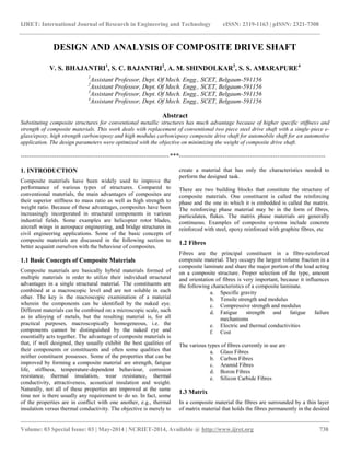
  • 4. IJRET: International Journal of Research in Engineering and Technology eISSN: 2319-1163 | pISSN: 2321-7308 __________________________________________________________________________________________ Volume: 03 Special Issue: 03 | May-2014 | NCRIET-2014, Available @ http://www.ijret.org 741 a) Length of shaft L = 1 m b) Outer radius of the shaft Ro = 50 mm with 5 mm thickness. c) Torque applied at free end of shaft 1.9.2 Assumptions In the analysis of the composite drive shaft following assumptions are made. 1. The shaft rotates at a constant speed about its longitudinal axis. 2. The shaft has a uniform, circular cross section. 3. The shaft is perfectly balanced, i.e., at every cross section, the mass centre coincides with the geometric centre. 4. All damping and nonlinear effects are excluded. 5. The stresses-strain relationship for composite material is linear and elastic, i.e., Hooke’s law is applicable for composite materials. 6. Acoustical fluid interactions are neglected, i.e., the shaft is assumed to be acting in a vacuum. 7. Since lamina is thin and no out-of-plane loads are applied, it is considered to be in plane stress condition. 1.9.3 Selection of Cross-Section The shaft can be solid circular or hollow circular. Here hollow circular cross-section was chosen because: i. The hollow circular shafts are stronger in per kg weight than solid circular shafts. ii. The stress distribution in case of solid shaft is zero at the centre and maximum at the outer surface while in hollow shaft stress variation is smaller. In solid shafts the material close to the centre are not fully utilized. 1.9.4 Selection of Reinforcement Fibre Fibres are available with widely differing properties. Review of the design and performance requirements usually dictate the fibre to be used. So in our analysis we will consider the Carbon fibres because its advantages include high specific strength and modulus, low coefficient of thermal expansion, and high fatigue strength which is ideal fibre for torque transmitting shaft. 1.9.5 Selection of Resin System The important considerations in selecting resin are cost, temperature capability, elongation to failure and resistance to impact (a function of modulus of elongation). The resins selected for most of the drive shafts are either epoxies or vinyl esters. Here, epoxy resin was selected due to its high strength, good wetting of fibres, lower curing shrinkage, and better dimensional stability. 1.9.6 Why Carbon Epoxy Composite? Following are the features of carbon epoxy composite, the reason for which it is chosen. 1. Carbon epoxy composite gives high tensile strength, high modulus of rigidity as compared to other composites. 2. Carbon epoxy composite has unique damping characteristic. 3. Carbon epoxy composite has positive coefficient of thermal expansion i.e. tensile strength of this composite increases with temperature. 4. Carbon epoxy composite is fatigue, wear and corrosion resistant. 1.9.7 Selection of Material Based on the advantages discussed above, the high strength and high modulus Carbon/Epoxy materials are selected for composite drive shaft. The Table 5.1 shows the properties of the Carbon/Epoxy material used for composite drive shaft. 1.9.8 Modal Analysis of Composite Shaft Modal analysis is used to determine the vibration characteristics such as natural frequencies and mode shapes of a structure or a machine component while it is being designed. A modal analysis can be performed using the ANSYS. The vibration problem is described by a set of equations, and there is a natural vibration mode for every equation that can be extracted by using an Eigen value extraction analysis. The displacement behaviour dominating any structure subject to vibration is global; therefore, modal analysis is utilized in these types of problems. In modal analysis, the model of the composite shaft does not need a fine mesh because the stress output is not required. Additionally, there is no requirement to input an applied load, because the natural frequency is only a function of mass and stiffness. The ends of the composite shaft model were modelled as simply-supported, and the boundary condition was varied until the value of the natural frequency became nearly coincident with that presented by a reliable example. It was recognized that the end support conditions must also be applied to the edges of the composite shaft. The rotational speed is limited by lateral stability considerations. Most designs are sub critical, i.e. rotational speed must be lower than the first natural bending frequency of the shaft. The natural frequency depends on the diameter of the shaft, thickness of the hollow shaft, specific stiffness and the length. Boundary conditions for the modal analysis are shown in Fig 5.3 below
  • 5. IJRET: International Journal of Research in Engineering and Technology eISSN: 2319-1163 | pISSN: 2321-7308 __________________________________________________________________________________________ Volume: 03 Special Issue: 03 | May-2014 | NCRIET-2014, Available @ http://www.ijret.org 742 1.9.9 Modelling of Conventional Steel Shaft Conventional drive shaft is made up of steel for most of the automobile, but sometimes aluminium is also used. To compare the capability of composite material, steel shaft strength is compared with composite. In present analysis conventional shaft is modelled in ANSYS and its length is considered as 1 m and diameter of the shaft as 50 mm with 2.032 mm thickness. Similar dimensions are used in composite shaft analysis. Steel material has young’s modulus of Ex = 210 GPa and Poisson ratio equal to 0.3. Comparison is carried out based on maximum deformation, maximum stresses induced in the shaft. Table 5.2 below shows the properties of steel. Table 2 Properties of steel Steel E = 207 e 9 N/m2 µ = 0.3 G = 80 e 9 N/m2 Density = 7600 Kg/m3 Max. Torque Tmax= 3000 N-m Now for the steel shaft the maximum stresses and maximum deflections are found out first and then modal analysis is done. Analysis procedure for steel shaft is the same as that for composite shaft. The only exception being the homogeneous, isotropic nature input, meaning the same value input for all directions. In the chapter that follows are presented the discussions about the results obtained from the above analysis, for various orientations and different layers of the composite shaft and for the steel shaft. 2. RESULTS AND DISCUSSIONS 2.1 Static Analysis The maximum shear stress and maximum deflection for each layer are obtained using ANSYS by varying the orientation of fibre in that layer by 100 and keeping the orientation of other layers constant i.e. 00 . 2.2 Variation of Stresses with Fibre Angle Orientation of Different Layers 2.2.1 Layer 1 Table 3 Variations in stresses by changing fibre angle orientation of layer 1 Configuration Layer 1 Layer 2 Layer 3 Layer 4 10/0/0/0 4.79E+06 2.98E+06 6.49E+06 3.25E+06 20/0/0/0 7.39E+06 2.86E+06 6.29E+06 3.20E+06 30/0/0/0 9.18E+06 2.74E+06 6.07E+06 3.16E+06 40/0/0/0 9.84E+06 2.68E+06 6.00E+06 3.13E+06 50/0/0/0 9.42E+06 2.71E+06 6.08E+06 3.19E+06 60/0/0/0 8.11E+06 2.80E+06 6.24E+06 3.23E+06 70/0/0/0 6.20E+06 2.91E+06 6.41E+06 3.26E+06 80/0/0/0 4.13E+06 2.99E+06 6.54E+06 3.27E+06 90/0/0/0 3.01E+06 3.02E+06 6.58E+06 3.28E+06 Fig 2 Variations in stresses by changing fibre angle orientation of layer 1 Fig. 1 Boundary conditions for the modal analysis for composite shaft
  • 6. IJRET: International Journal of Research in Engineering and Technology eISSN: 2319-1163 | pISSN: 2321-7308 __________________________________________________________________________________________ Volume: 03 Special Issue: 03 | May-2014 | NCRIET-2014, Available @ http://www.ijret.org 743 2.2.2 Layer 2 Table 4 Variations in stresses by changing fibre angle orientation of layer Configuration Layer1 Layer2 Layer3 Layer4 0/10/0/0 2.97E+06 4.80E+06 6.48E+06 3.24E+06 0/20/0/0 2.85E+06 7.37E+06 6.29E+06 3.17E+06 0/30/0/0 2.73E+06 9.12E+06 6.04E+06 3.11E+06 0/40/0/0 2.67E+06 9.74E+06 5.95E+06 3.10E+06 0/50/0/0 2.70E+06 9.30E+06 6.02E+06 3.13E+06 0/60/0/0 2.79E+06 8.01E+06 6.19E+06 3.18E+06 0/70/0/0 2.90E+06 6.13E+06 6.38E+06 3.23E+06 0/80/0/0 2.98E+06 4.11E+06 6.53E+06 3.26E+06 0/90/0/0 3.01E+06 3.02E+06 6.58E+06 3.27E+06 Fig 3 Variations in stresses by changing fibre angle orientation of layer 2 2.2.3 Layer 3 Table 5 Variations in stresses by changing fibre angle orientation of layer 3 Fig 4 Variations in stresses by changing fibre angle orientation of layer 3 2.2.4 Layer 4 Table 6 Variations in stresses by changing fibre angle orientation of layer 4 Configurat ion deflection1 Deflection 2 Deflection3 Deflection4 10/0/0/0 2.82E-04 2.82E-04 2.82E-04 2.82E-04 20/0/0/0 2.71E-04 2.71E-04 2.71E-04 2.71E-04 30/0/0/0 2.60E-04 2.60E-04 2.60E-04 2.60E-04 40/0/0/0 2.54E-04 2.54E-04 2.54E-04 2.54E-04 50/0/0/0 2.57E-04 2.57E-04 2.57E-04 2.57E-04 60/0/0/0 2.66E-04 2.66E-04 2.66E-04 2.66E-04 70/0/0/0 2.76E-04 2.76E-04 2.76E-04 2.76E-04 80/0/0/0 2.84E-04 2.84E-04 2.84E-04 2.84E-04 90/0/0/0 2.87E-04 2.87E-04 2.87E-04 2.87E-04 Configuration LAYER1 LAYER2 LAYER3 LAYER4 0/0/0/10 2.91E+06 2.91E+06 7.05E+06 4.30E+06 0/0/0/20 2.65E+06 2.63E+06 7.42E+06 5.70E+06 0/0/0/30 2.37E+06 2.39E+06 7.69E+06 6.21E+06 0/0/0/40 2.29E+06 2.35E+06 7.73E+06 6.19E+06 0/0/0/50 2.36E+06 2.42E+06 7.60E+06 5.91E+06 0/0/0/60 2.58E+06 2.57E+06 7.36E+06 5.30E+06 0/0/0/70 2.80E+06 2.80E+06 7.03E+06 4.42E+06 0/0/0/80 2.96E+06 2.96E+06 6.72E+06 3.50E+06 0/0/0/90 3.01E+06 3.02E+06 6.58E+06 3.25E+06
  • 7. IJRET: International Journal of Research in Engineering and Technology eISSN: 2319-1163 | pISSN: 2321-7308 __________________________________________________________________________________________ Volume: 03 Special Issue: 03 | May-2014 | NCRIET-2014, Available @ http://www.ijret.org 744 2.3 Variation of Deflection with Fibre Angle Orientation of Different Layers 2.3.1 Layer 1 Variations in deflection by changing fibre angle orientation of layer 1 2.3.2 Layer 2 Figure 6.5 Variations in deflection by changing fibre angle orientation of layer 1 Table 7 Variations in deflection by changing fibre angle orientation of layer 2 2.3.3 Layer 3 Table 8 Variations in deflection by changing fibre angle orientation of layer 3 Configur ation Deflectio n1 Deflectio n2 Deflectio n3 Deflectio n4 0/10/0/0 2.82E-04 2.82E-04 2.82E-04 2.82E-04 0/20/0/0 2.71E-04 2.71E-04 2.71E-04 2.71E-04 0/30/0/0 2.59E-04 2.59E-04 2.59E-04 2.59E-04 0/40/0/0 2.54E-04 2.54E-04 2.54E-04 2.54E-04 0/50/0/0 2.57E-04 2.57E-04 2.57E-04 2.57E-04 0/60/0/0 2.65E-04 2.65E-04 2.65E-04 2.65E-04 0/70/0/0 2.76E-04 2.76E-04 2.76E-04 2.76E-04 0/80/0/0 2.84E-04 2.84E-04 2.84E-04 2.84E-04 0/90/0/0 2.87E-04 2.87E-04 2.87E-04 2.87E-04 Configu ration Deflection 1 Deflectio n2 Deflection 3 Deflectio n4 0/0/10/0 2.60E-04 2.60E-04 2.60E-04 2.60E-04 0/0/20/0 2.11E-04 2.11E-04 2.11E-04 2.11E-04 0/0/30/0 1.85E-04 1.85E-04 1.85E-04 1.85E-04 0/0/40/0 1.88E-04 1.88E-04 1.88E-04 1.88E-04 0/0/50/0 2.09E-04 2.09E-04 2.09E-04 2.09E-04 0/0/60/0 2.36E-04 2.36E-04 2.36E-04 2.36E-04 0/0/70/0 2.62E-04 2.62E-04 2.62E-04 2.62E-04 0/0/80/0 2.81E-04 2.81E-04 2.81E-04 2.81E-04 0/0/90/0 2.87E-04 2.87E-04 2.87E-04 2.87E-04 Configurati on Deflectio n1 Deflectio n2 Deflectio n3 Deflectio n4 0/0/0/10 2.66E-04 2.66E-04 2.66E-04 2.66E-04 0/0/0/20 2.25E-04 2.25E-04 2.25E-04 2.25E-04 0/0/0/30 1.99E-04 1.99E-04 1.99E-04 1.99E-04 0/0/0/40 1.99E-04 1.99E-04 1.99E-04 1.99E-04 0/0/0/50 2.16E-04 2.16E-04 2.16E-04 2.16E-04 0/0/0/60 2.40E-04 2.40E-04 2.40E-04 2.40E-04 0/0/0/70 2.64E-04 2.64E-04 2.64E-04 2.64E-04 0/0/0/80 2.81E-04 2.81E-04 2.81E-04 2.81E-04 0/0/0/90 2.87E-04 2.87E-04 2.87E-04 2.87E-04
  • 8. IJRET: International Journal of Research in Engineering and Technology eISSN: 2319-1163 | pISSN: 2321-7308 __________________________________________________________________________________________ Volume: 03 Special Issue: 03 | May-2014 | NCRIET-2014, Available @ http://www.ijret.org 745 Fig 5 Variations in deflection by changing fibre angle orientation of layer 3 2.3.4 Layer 4 Variations in deflection by changing fibre angle orientation of layer 4 Fig 6 Variations in deflection by changing fibre angle orientation of layer 4 10.3 Comparison of Composite Shaft with Shaft made up of Steel Conventional drive shaft is made up of steel for most of the automobile, but sometimes aluminium is also used. To understand the effect of composite material in design, strength of the steel shaft is compared with that of the composite shaft. In the present analysis conventional shaft was modelled with its length as 1 m, diameter 0.05 m and thickness 0.002032 m. The same dimensions are used for the analysis of composite shaft. Comparison is carried out based on maximum deformation and maximum stresses induced in the shaft. 3. CONCLUSIONS Following conclusions are drawn from the results obtained from these analyses- 1. The High Strength Carbon/Epoxy and High Modulus Carbon/Epoxy Composite drive shafts have been designed to replace the steel drive shaft of an automobile 2. The weight savings of the High strength carbon/epoxy and high modulus carbon/epoxy shafts were equal to 50 % approximately of the steel shaft 3. Optimum fibre angle orientation will play important role in composite shaft which depends on requirement of composite shaft 4. The design procedure is studied and along with finite element analysis some important parameter are obtained. The composite drive shaft made up of HM carbon / epoxy multilayered composites has been designed. The results reveal that the orientation of fibres has great influence on the static characteristics of the composite shafts and offers advantages such as a. Lower weight b. Higher strength c. Progressive failure mechanism (offers warning before failure) d. Lower power consumption 5. The present finite element analysis of the design variables provide an insight of their effects on the drive shaft’s critical mechanical characteristics and fatigue resistance. A model of hybridized layers was generated incorporating carbon-epoxy. The buckling, which dominates the failure mode, have a value which not increases regularly with increasing the winding angle. 6. Regression Analysis was done to obtain relations between fibre angle orientation and parameters like stresses induced in each layer, deflection in each layer and natural frequencies of the composite shaft. 7. This relation helps in finding the above mentioned parameters at any fibre orientation; which will help to optimize the design of a composite shaft and hence will reduce the cost of manufacturing. REFERENCES [1] T. Rangaswamy, et al., “Optimal design and analysis of automotive composite drive shaft”, 2004. [2] M. A. Badie, et al., “Automotive composite driveshafts: investigation of the design variables effects” 2006, pp. 227-237. [3] Y. A. Khalid, et al, “Bending fatigue behavior of hybrid aluminum/composite drive shafts”, 2005. [4] A. R. Abu Talib, et al., “Developing a hybrid, carbon/glass fiber-reinforced, epoxy composite automotive drive shaft”, 2010, pp. 514-521. [5] A. Gebresilassie, “Design and analysis of composite drive shaft for rear-wheel drive engine”, Volume 3, Issue 5, May-2012.D. Jebakani, T. Paul Robert, “Particle swarm optimization for RBDO of composite drive shaft”, European Journal of Scientific Research, Steel Composite Max stresses 0.897e+07 0.424e+07 Deflection 0.249e-03 0.152e-04