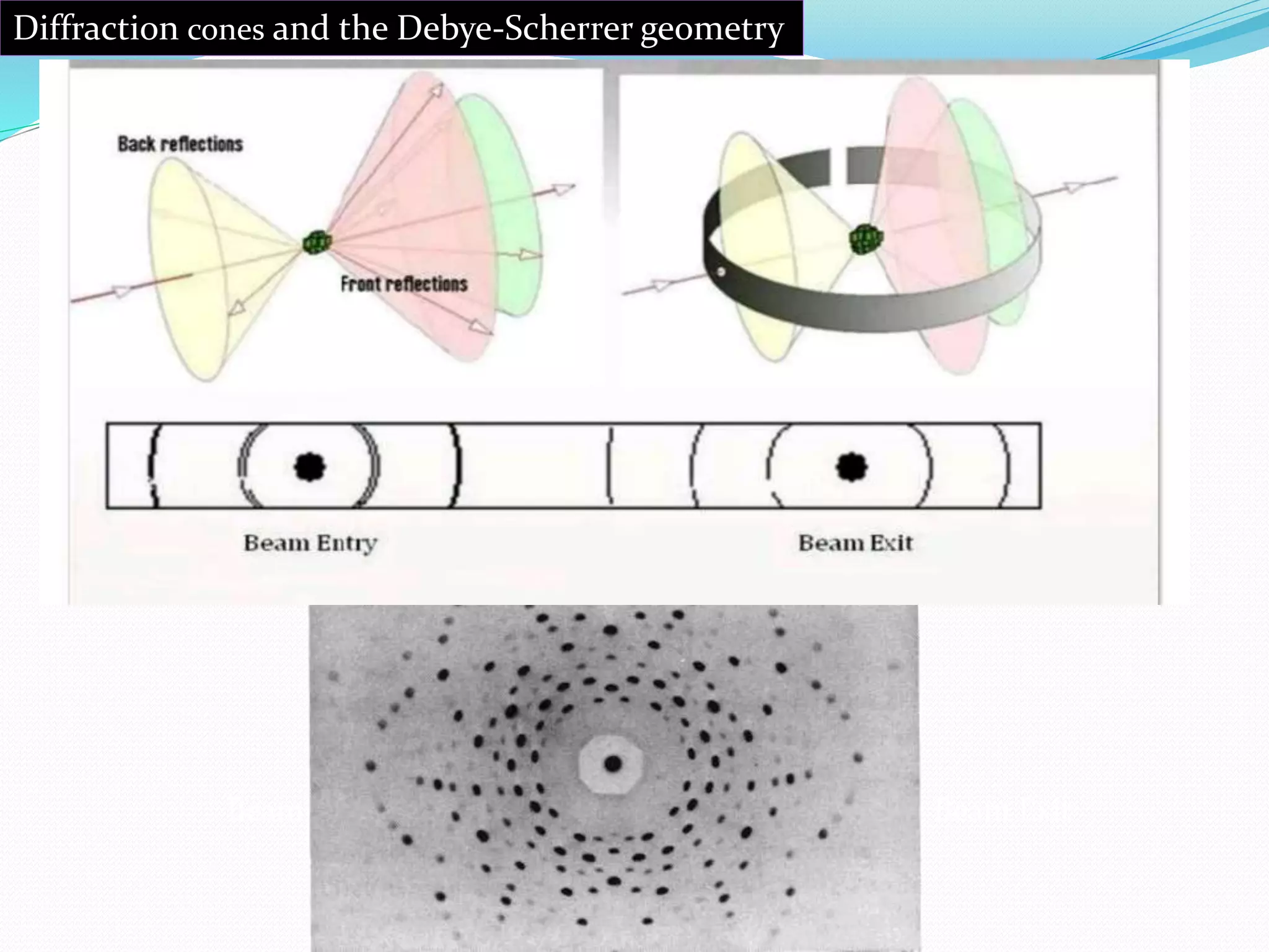
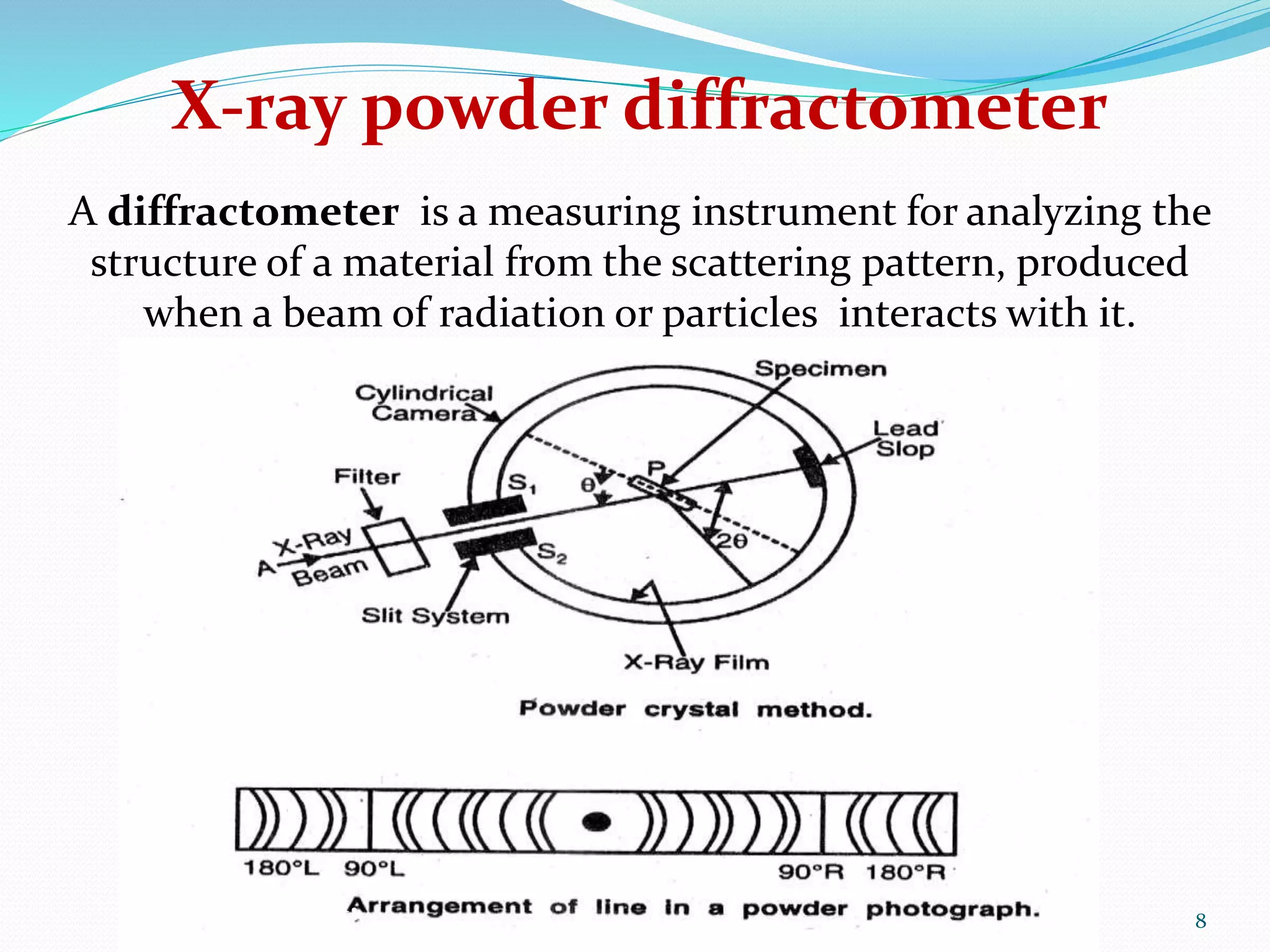
PRESENTED BY SUBMITTED TO
Chiranjibi Adhikari Mrs. Menaka T.
M. Pharm. 1
st
year Assistant professor
Mallige College of Pharmacy
#71, SILVEPURA, BANGALORE: 560 090
EVALUATION SEMINAR ON
2
 Introduction to X-ray powder diffraction
 Fundamental principles
 X-ray powder diffractometer
 Obtaining of XRD data
 Applications
 Strength & Limitations
X-RAY POWDER DIFFRACTION
 Diffraction is defined as the bending of light around or into
the geometrical shadow of the obstacle.
 In powder X-ray diffraction, the diffraction pattern is obtained
from a powder of the material, rather than an individual
crystal.
 Powder diffraction is often easier and more convenient than
single crystal diffraction as about 1 mg of material is sufficient
for the study.
3
 Max von Laue, in 1912, discovered that crystalline
substances act as three-dimensional diffraction
gratings for X-ray wavelengths similar to the
spacing of planes in a crystal lattice.
 The powder method was devised independently by
Debye and Scherrer in Germany and by Hull in
America at about the same time.
4
 X-ray diffraction is based on constructive interference of
monochromatic X-rays and a crystalline sample.
 For every set of crystal planes in the fine powder, one or more
crystals will be in the correct orientation to give the correct
Bragg angle to satisfy Bragg's equation.
 Another fraction of the grains will have another set of planes
in the correct position for the reflection to occur and so on.
 Also, reflections are possible in the different order for each set.
 The powdered sample generates the concentric cones of
diffracted X-rays because of the random orientation of
crystallites in the sample.
5
FUNDAMENTAL PRINCIPLES OF XRD
Beam Entry Beam Exit
Diffraction cones and the Debye-Scherrer geometry
 All the like orientations of the grains due to reflection for each
set of planes and for each order will constitute a diffraction
cone whose interaction with the photographic plate gives rise
to a trace.
 Instead of the sample generating only single diffraction spots,
it generates cones of diffracted X-rays, with the point of all of
the cones at the sample.
 The x-ray pattern of a pure crystalline substance can be
considered as a fingerprint with each crystalline material
having, within limits, a unique diffraction pattern.
7
8
X-ray powder diffractometer
A diffractometer is a measuring instrument for analyzing the
structure of a material from the scattering pattern, produced
when a beam of radiation or particles interacts with it.
Figure 1.
9
 A is a source of X-rays.These X-rays are generated by a
cathode ray tube.
 X-rays are filtered by monochromator to produce
monochromatic radiation. It help to choose the correct
wavelength.
 Slits (S1 and S2) are used to adjust the shape of the
beam, collimate to concentrate and direct the X-rays
beam toward the sample so that the powdered
specimen (P) get a narrow pencil of X-rays.
 Fine powder is struck on a hair by means of gum. It is
suspended vertically in the axis of a cylindrical camera.
This enables sharp lines to be obtained on the
photographic film which is surrounding the powder
crystal in the form of a circular arc.
10
 The X-rays after falling on the powder passes out of the
camera through a cut in the film so as to minimize the
fogging produced by the scattering of the direct beam.
 When the geometry of the incident X-rays impinging
the sample satisfies the Bragg Equation, constructive
interference occurs and the intensity of the reflected
X-rays is recorded by a detector.
 The detector also processes this X-ray signal and
convert it into a count rate, which is then output to a
device such as a printer or computer monitor.
 In a more complicated apparatus, also a goniometer
can be used for fine adjustment of the sample and the
detector positions.
11
Obtaining of XRD data
 The crystal structure can be obtained from the
arrangement of the traces and their relative intensities.
 A diffraction pattern plots intensity against the angle of
the detector, 2θ. The result obtained is called
diffractogram.
 In a diffraction pattern, the peak position depends upon
the wavelength.
 Absolute intensity (number of X-rays observed in an
given peak) may vary by instrumental and experimental
parameters.
12
13
The peaks represent positions where the X-ray beam has been
diffracted by the crystal lattice. The set of d-spacings, which
represent the unique "fingerprint" of the mineral, can easily be
calculated from the 2-theta values shown.
14
X-ray diffraction provides ample information about the lattice
parameters. Peak represents a lattice plane and therefore can
be characterized by Miller index.
If the symmetry is high as in case of cubic or hexagonal, it is
not difficult to identify the peak index for an unknown phase.
This is very useful in solid-state chemistry to identifying new
materials. Once a pattern gets indexed, it serves as reference
for new entities.
Each peak in pattern is a reflection from a different set of
planes. By determining 2 for a peak, can use Braggs' law to get
d for that set of planes
15
APPLICATION IN POLYMORPHISM
PXRD is helpful in identification and characterization of
polymorph, monitoring the stability, method development and
validation for identification and quantification of drugs in
Pharmaceutical Industries.
It helps in elucidation of the relevant polymorphic and pseudo-
polymorphic forms in pharmaceutical development.
16
17
The atoms in a crystal are periodically arranged, producing
constructive interference at specific angles thus diffract light.
The wavelength of X-ray are similar to the distance between
atoms, Powder X-ray Diffraction techniques uses this principle to
elucidate the crystalline nature of materials.
The scattering of X-rays from atoms produce a diffraction pattern
that contains information about the atomic arrangement in
crystal.
Amorphous materials like glass do not have periodic array with
long-range order so; they do not produce any significant peak in
diffraction pattern.
OTHER APPLICATIONS
 Powder (polycrystalline) diffraction is commonly
used for chemical analysis- phase identification.
 Identification of unknown crystalline materials
(e.g. minerals, inorganic compounds).
 Identification of fine-grained minerals such as
clays and mixed layer clays that are difficult to
determine optically.
 Determination of unit cell dimensions.
18
• Measurement of sample purity .
• Most useful for cubic crystal.
• Used for determining the complex structure of
metals and alloys.
• Useful to make distinction between the
allotropic modifications of the same substance.
19
STRENGTHS OF X-RAY POWDER DIFFRACTION
 Powerful and rapid (< 20 min) technique for
identification of an unknown mineral.
 In most cases, it provides a clear structural
determination.
 XRD units are widely available.
 Data interpretation is relatively straight forward .
20
LIMITATIONS OF X-RAY POWDER DIFFRACTION
 For mixed materials, detection limit is ~ 2% of sample.
 Peak overlay may occur and worsens for high angle
reflections.
 For unit cell determinations, indexing of patterns for non-
isometric crystal systems is complicated.
21
X-Ray Powder Diffraction is a somewhat inefficient
measurement technique…
 Only a small fraction of crystallites in the sample actually
contribute to the observed diffraction pattern.
– Other crystallites are not oriented properly to produce
diffraction from any planes of atoms.
– You can increase the number of crystallites that contribute to
the measured pattern by spinning the sample.
 Only a small fraction of the scattered X-rays are observed by
the detector.
– A point detector scanning in an arc around the sample only
observes one point on each Debye diffraction cone.
– You can increase the amount of scattered X-rays observed by
using a large area (2D) detector.
22
REFERENCES
 Instrumental methods of chemical analysis by G R Chatwal
& Sham K Anand. Page No. 2.324-2.326
 Chauhan and Chauhan. Powder XRD Technique and its
Applications in Science and Technology. J Anal Bioanal
Tech 2014; 5(5):1-5.
 http://serc.carleton.edu/research_education/geoche
msheets/techniques/XRD.html
 http://pubs.usgs.gov/info/diffraction/html/
23
24

X ray powder diffraction

  • 1.
    PRESENTED BY SUBMITTEDTO Chiranjibi Adhikari Mrs. Menaka T. M. Pharm. 1 st year Assistant professor Mallige College of Pharmacy #71, SILVEPURA, BANGALORE: 560 090 EVALUATION SEMINAR ON
  • 2.
    2  Introduction toX-ray powder diffraction  Fundamental principles  X-ray powder diffractometer  Obtaining of XRD data  Applications  Strength & Limitations
  • 3.
    X-RAY POWDER DIFFRACTION Diffraction is defined as the bending of light around or into the geometrical shadow of the obstacle.  In powder X-ray diffraction, the diffraction pattern is obtained from a powder of the material, rather than an individual crystal.  Powder diffraction is often easier and more convenient than single crystal diffraction as about 1 mg of material is sufficient for the study. 3
  • 4.
     Max vonLaue, in 1912, discovered that crystalline substances act as three-dimensional diffraction gratings for X-ray wavelengths similar to the spacing of planes in a crystal lattice.  The powder method was devised independently by Debye and Scherrer in Germany and by Hull in America at about the same time. 4
  • 5.
     X-ray diffractionis based on constructive interference of monochromatic X-rays and a crystalline sample.  For every set of crystal planes in the fine powder, one or more crystals will be in the correct orientation to give the correct Bragg angle to satisfy Bragg's equation.  Another fraction of the grains will have another set of planes in the correct position for the reflection to occur and so on.  Also, reflections are possible in the different order for each set.  The powdered sample generates the concentric cones of diffracted X-rays because of the random orientation of crystallites in the sample. 5 FUNDAMENTAL PRINCIPLES OF XRD
  • 6.
    Beam Entry BeamExit Diffraction cones and the Debye-Scherrer geometry
  • 7.
     All thelike orientations of the grains due to reflection for each set of planes and for each order will constitute a diffraction cone whose interaction with the photographic plate gives rise to a trace.  Instead of the sample generating only single diffraction spots, it generates cones of diffracted X-rays, with the point of all of the cones at the sample.  The x-ray pattern of a pure crystalline substance can be considered as a fingerprint with each crystalline material having, within limits, a unique diffraction pattern. 7
  • 8.
    8 X-ray powder diffractometer Adiffractometer is a measuring instrument for analyzing the structure of a material from the scattering pattern, produced when a beam of radiation or particles interacts with it. Figure 1.
  • 9.
  • 10.
     A isa source of X-rays.These X-rays are generated by a cathode ray tube.  X-rays are filtered by monochromator to produce monochromatic radiation. It help to choose the correct wavelength.  Slits (S1 and S2) are used to adjust the shape of the beam, collimate to concentrate and direct the X-rays beam toward the sample so that the powdered specimen (P) get a narrow pencil of X-rays.  Fine powder is struck on a hair by means of gum. It is suspended vertically in the axis of a cylindrical camera. This enables sharp lines to be obtained on the photographic film which is surrounding the powder crystal in the form of a circular arc. 10
  • 11.
     The X-raysafter falling on the powder passes out of the camera through a cut in the film so as to minimize the fogging produced by the scattering of the direct beam.  When the geometry of the incident X-rays impinging the sample satisfies the Bragg Equation, constructive interference occurs and the intensity of the reflected X-rays is recorded by a detector.  The detector also processes this X-ray signal and convert it into a count rate, which is then output to a device such as a printer or computer monitor.  In a more complicated apparatus, also a goniometer can be used for fine adjustment of the sample and the detector positions. 11
  • 12.
    Obtaining of XRDdata  The crystal structure can be obtained from the arrangement of the traces and their relative intensities.  A diffraction pattern plots intensity against the angle of the detector, 2θ. The result obtained is called diffractogram.  In a diffraction pattern, the peak position depends upon the wavelength.  Absolute intensity (number of X-rays observed in an given peak) may vary by instrumental and experimental parameters. 12
  • 13.
    13 The peaks representpositions where the X-ray beam has been diffracted by the crystal lattice. The set of d-spacings, which represent the unique "fingerprint" of the mineral, can easily be calculated from the 2-theta values shown.
  • 14.
    14 X-ray diffraction providesample information about the lattice parameters. Peak represents a lattice plane and therefore can be characterized by Miller index. If the symmetry is high as in case of cubic or hexagonal, it is not difficult to identify the peak index for an unknown phase. This is very useful in solid-state chemistry to identifying new materials. Once a pattern gets indexed, it serves as reference for new entities. Each peak in pattern is a reflection from a different set of planes. By determining 2 for a peak, can use Braggs' law to get d for that set of planes
  • 15.
    15 APPLICATION IN POLYMORPHISM PXRDis helpful in identification and characterization of polymorph, monitoring the stability, method development and validation for identification and quantification of drugs in Pharmaceutical Industries. It helps in elucidation of the relevant polymorphic and pseudo- polymorphic forms in pharmaceutical development.
  • 16.
  • 17.
    17 The atoms ina crystal are periodically arranged, producing constructive interference at specific angles thus diffract light. The wavelength of X-ray are similar to the distance between atoms, Powder X-ray Diffraction techniques uses this principle to elucidate the crystalline nature of materials. The scattering of X-rays from atoms produce a diffraction pattern that contains information about the atomic arrangement in crystal. Amorphous materials like glass do not have periodic array with long-range order so; they do not produce any significant peak in diffraction pattern.
  • 18.
    OTHER APPLICATIONS  Powder(polycrystalline) diffraction is commonly used for chemical analysis- phase identification.  Identification of unknown crystalline materials (e.g. minerals, inorganic compounds).  Identification of fine-grained minerals such as clays and mixed layer clays that are difficult to determine optically.  Determination of unit cell dimensions. 18
  • 19.
    • Measurement ofsample purity . • Most useful for cubic crystal. • Used for determining the complex structure of metals and alloys. • Useful to make distinction between the allotropic modifications of the same substance. 19
  • 20.
    STRENGTHS OF X-RAYPOWDER DIFFRACTION  Powerful and rapid (< 20 min) technique for identification of an unknown mineral.  In most cases, it provides a clear structural determination.  XRD units are widely available.  Data interpretation is relatively straight forward . 20
  • 21.
    LIMITATIONS OF X-RAYPOWDER DIFFRACTION  For mixed materials, detection limit is ~ 2% of sample.  Peak overlay may occur and worsens for high angle reflections.  For unit cell determinations, indexing of patterns for non- isometric crystal systems is complicated. 21
  • 22.
    X-Ray Powder Diffractionis a somewhat inefficient measurement technique…  Only a small fraction of crystallites in the sample actually contribute to the observed diffraction pattern. – Other crystallites are not oriented properly to produce diffraction from any planes of atoms. – You can increase the number of crystallites that contribute to the measured pattern by spinning the sample.  Only a small fraction of the scattered X-rays are observed by the detector. – A point detector scanning in an arc around the sample only observes one point on each Debye diffraction cone. – You can increase the amount of scattered X-rays observed by using a large area (2D) detector. 22
  • 23.
    REFERENCES  Instrumental methodsof chemical analysis by G R Chatwal & Sham K Anand. Page No. 2.324-2.326  Chauhan and Chauhan. Powder XRD Technique and its Applications in Science and Technology. J Anal Bioanal Tech 2014; 5(5):1-5.  http://serc.carleton.edu/research_education/geoche msheets/techniques/XRD.html  http://pubs.usgs.gov/info/diffraction/html/ 23
  • 24.