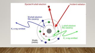
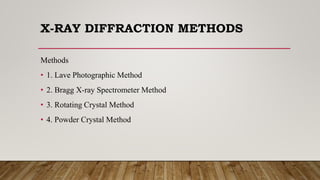
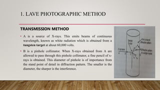
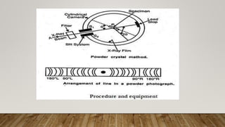
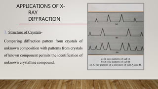
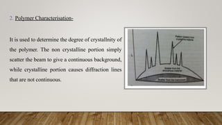
X-RAY CRYSTALLOGRAPHY
PRESENTED BY:-
SILAMBARASAN I
M.PHARM(PHARMACEUTICS)
MTPG & RIHS
X-RAY/RONTGEN RADIATION
German physicist Wilhelm Rontgen- 1895.
 Form of electromagnetic radiation.
Wavelength- 0.01 to 10 nanometers.
Frequency- 3×10¹⁶ Hz to 3×10¹⁹ Hz.
Energy- 100eV to 100keV
They have shorter wavelength than UV but longer than those of Gamma radiation.
CRYSTALLOGRAPHY
Crystallography is deals with , investigating matter in the crystalline state.
"Crystallography", greek words crystallon "cold drop, frozen drop”
and graphein "to write".
A crystal is a solid material whose constituent atoms, molecules or ions are
arranged in regular manner.
METTALIC CRYSTALS
•Copper, Silver, Aluminum,Tungsten,
Magnesium etc.
NON-METALLIC CRYSTALS
•Ice, Carbon, Diamond, Sodium
Chloride, Pottasium Chloride etc.
CRYSTALS
INTRODUCTION TO X-RAY
CRYSTALLOGRAPHY
 X-ray crystallography is a technique used for determining the atomic and
molecular structure of a crystal, in which the crystalline atoms cause a beam
of incident x-rays to diffract into many specific directions.
 By measuring the angles and intensities of these diffracted beams, a
crystallographer can produce a three- dimensional picture of the density of
electrons.
 From this electron density, the mean positions of the atoms, chemical bond in
the crystal can be determined.
DIFFERENT X-RAY
METHODS
1. X-RAYABSORPTION METHOD :-
 The intensity of X-ray is diminished as they pass through material.
 Used to detect concentration of sample.
 Used in elemental analysis of barium and iodine in body.
DIFFERENT X-RAY
METHODS
2. X-RAY FLUORESCENCE METHOD
 Atom is excited by removal of electron from an inner energy shell,
it may return to normal to its normal state by transferring an
electron from some outer level to vacant inner shell .
 Used for qualitative and quantitative analysis.
DIFFERENT X-RAY
METHODS
3. X-RAY DIFFRACTION METHOD
 When a beam of monochromatic X radiation is directed at a crystalline
material, one observes reflection or diffraction of the X-rays at a various
angle with respect to the primary beam.
 The relationship between the X-radiation, angle of diffraction and distance
between each set of atomic planes of crystal lattice is given by Bragg’s
equation.
nλ= 2dsinθ
X-RAY DIFFRACTION METHODS
Methods
• 1. Lave Photographic Method
• 2. Bragg X-ray Spectrometer Method
• 3. Rotating Crystal Method
• 4. Powder Crystal Method
LAVE PHOTOGRAPHIC
METHOD
Lave has studied the phenomenon of diffraction of crystal by two methods
oTransmission method
o Back reflection method
1. LAVE PHOTOGRAPHIC METHOD
TRANSMISSION METHOD
• A is a source of X-rays. This emits beams of continuous
wavelength, known as white radiation which is obtained from a
tungsten target at about 60,000 volts.
• B is a pinhole collimator. When X-rays obtained from A are
allowed to pass through this pinhole collimator, a fine pencil of x-
rays is obtained. This diameter of pinhole is of importance from
the stand point of detail in diffraction pattern. The smaller is the
diameter, the sharper is the interference.
CONT,
• C is a crystal whose internal structure is to be investigated.
• D is a fine arranged on a rigid base. This film is provided with beam stop
to prevent direct beam from causing excessive fogging of the film.
• The x-rays are recorded on photographic plate and study of diffraction
patterns helps to know the structure of crystal.
b) BACK REFLECTION METHOD-
 In the back reflection method, the film is placed between the x-ray source
and the crystal. The beam which are diffracted in a backward direction are
recorded.
 Disadvantage - big crystal is required.
X-ray Diffraction Methods
2.BRAGG X-RAY SPECTROMETER METHOD
• When x-rays are scattered from a crystal lattice, peaks of
scattered intensity are observed which correspond to the
following conditions:
1.The angle of incidence = angle of scattering.
2.The path length difference is equal to an integer number of
wavelengths.
• The condition for maximum intensity contained in Bragg's
law above allow us to calculate details about the crystal
structure, or if the crystal structure is known, to determine
the wavelength of the x-rays incident upon the crystal.
CONT,
• The Braggs equation is nλ= 2dsinθ
• where n is a positive integer
• λ is the wavelength of incident wave
• d is the path length
• Θ is the incident angle
3.ROTATING CRYSTAL METHOD
• The rotating crystal method was developed by Schielbold
in 1919.
• The X-ray beam passed to the crystal through collimating
system.
• The rotating shaft hold the crystal and it also rotates.
• This causes the sets of planes coming successively into
their reflecting positions.
• Each plane will produce a spot on photographic plate.
4.POWDER CRYSTAL METHOD
• X-ray powder diffraction (XRD) is a rapid analytical technique primarily
used for phase identification of a crystalline material and can provide
information on unit cell dimensions.
• The analyzed material is finely ground and homogenized.
• A is a source of X-rays which can be made monochromatic by a filter.
• Allow the X-ray beam to fall on the powdered specimen P through the slits
S1 and S2.
CONT,
• Fine powder, p, struck on a hair by means of gum is suspended vertically
in the axis of a cylindrical camera. This enables sharp lines to be obtained
on the photographic film which is surrounding the powder crystal in the
form of a circular arc.
INSTRUMENTATIO
N
1. PRODUCTION OF X-RAY
2.COLLIMATOR
3. MONOCHROMATOR
a) FILTER
b) CRYSTALMONOCHROMATOR
4. CRYSTAL
5. DETECTORS
PRODUCTION OF X-RAYS
X-rays are generated via interactions of the accelerated electrons with electrons of
tungsten nuclei within the tube anode.
As the electrons bombard the target they interact which result in the conversion of
energy into heat (99%) and x-ray photons (1%).
The x-ray photons are released in a beam with a range of energies (x-ray
spectrum) out of the window of the tube and form the basis for x-ray image
formation.
EQUIPMENT
COLLIMA
TOR
In order to get a narrow beam of X-
rays, the X-rays generated by the target
material are allowed to pass through a
collimator which consists of two sets of
closely packed metal plates separated
by a small gap.
MONOCHROMATO
R
In order to monochromatize the x-rays two methods are available-
a) FILTER-
The X-ray beam may be partly monochromatized by the insertion of a suitable filter.
TARGET ELEMENT FILTER THICKNESS
Cobalt Iron 0.012mm
Copper Nickel 0.015mm
Iron Manganese 0.011mm
Molybdenum Zirconium 0.081mm
Nickel Cobalt 0.013mm
b) CRYSTALMONOCHROMATORS-
 It is made up of suitable crystalline material positioned in the X-ray
beam so that angle of the reflecting planes satisfied the Bragg’s
equation for the required wavelength.
 The beam is split up by the crystal.
 The crystals used are made up of sodium chloride, lithium
flouide, quartz etc.
CURVED CRYSTAL
CHROMATOR
FLAT CRYSTAL
CHROMATOR
DETECTORS
The X-ray intensities can be measured and recorded on a plane or cylindrical
photographic film. The film after exposing to X-rays is developed. The blackening
of the developed film is expressed in terms of density units D given by-
D= log I0/I
Where I0 refers to the incident intensity of X-ray
I refers to the transmitted intensity of X-ray
The value of D is measured by densitometer.
APPLICATIONS OF X-
RAY
DIFFRACTION
1. Structure of Crystals-
Comparing diffraction pattern from crystals of
unknown composition with patterns from crystals
of known component permits the identification of
unknown crystalline compound.
2. Polymer Characterisation-
It is used to determine the degree of crystallnity of
the polymer. The non crystalline portion simply
scatter the beam to give a continuous background,
while crystalline portion causes diffraction lines
that are not continuous.
3. Particle size determination-
Spot counting method-
Where
v= V.δθ.cosθ/2n
v= volume or size of individual crystallite,
V= total volume of specimen irradiated,
n= no. of spots in a diffraction ring at a bragg angle of θ
δθ= divergence of x-ray beam
5. Determination of cis and trans isomers.
6. Determination of linkage isomerism.
7. Soil classification based on crystallinity.
8. To assess the weathering and degradation of natural and synthetic minerals.
9. The products of corrosion can be identified by XRD, also by research, the factors
that affect the corrosion rate can be determined.
10. Tooth decay and dentine have been examined by XRD.
11. Identification of crystalline compound in the body.
12. It reveals some of the effects of diseases on bone structure and tissue structure.
X ray Crystallography

X ray Crystallography

  • 1.
    X-RAY CRYSTALLOGRAPHY PRESENTED BY:- SILAMBARASANI M.PHARM(PHARMACEUTICS) MTPG & RIHS
  • 2.
    X-RAY/RONTGEN RADIATION German physicistWilhelm Rontgen- 1895.  Form of electromagnetic radiation. Wavelength- 0.01 to 10 nanometers. Frequency- 3×10¹⁶ Hz to 3×10¹⁹ Hz. Energy- 100eV to 100keV They have shorter wavelength than UV but longer than those of Gamma radiation.
  • 4.
    CRYSTALLOGRAPHY Crystallography is dealswith , investigating matter in the crystalline state. "Crystallography", greek words crystallon "cold drop, frozen drop” and graphein "to write".
  • 5.
    A crystal isa solid material whose constituent atoms, molecules or ions are arranged in regular manner. METTALIC CRYSTALS •Copper, Silver, Aluminum,Tungsten, Magnesium etc. NON-METALLIC CRYSTALS •Ice, Carbon, Diamond, Sodium Chloride, Pottasium Chloride etc. CRYSTALS
  • 6.
    INTRODUCTION TO X-RAY CRYSTALLOGRAPHY X-ray crystallography is a technique used for determining the atomic and molecular structure of a crystal, in which the crystalline atoms cause a beam of incident x-rays to diffract into many specific directions.  By measuring the angles and intensities of these diffracted beams, a crystallographer can produce a three- dimensional picture of the density of electrons.  From this electron density, the mean positions of the atoms, chemical bond in the crystal can be determined.
  • 7.
    DIFFERENT X-RAY METHODS 1. X-RAYABSORPTIONMETHOD :-  The intensity of X-ray is diminished as they pass through material.  Used to detect concentration of sample.  Used in elemental analysis of barium and iodine in body.
  • 8.
    DIFFERENT X-RAY METHODS 2. X-RAYFLUORESCENCE METHOD  Atom is excited by removal of electron from an inner energy shell, it may return to normal to its normal state by transferring an electron from some outer level to vacant inner shell .  Used for qualitative and quantitative analysis.
  • 9.
    DIFFERENT X-RAY METHODS 3. X-RAYDIFFRACTION METHOD  When a beam of monochromatic X radiation is directed at a crystalline material, one observes reflection or diffraction of the X-rays at a various angle with respect to the primary beam.  The relationship between the X-radiation, angle of diffraction and distance between each set of atomic planes of crystal lattice is given by Bragg’s equation. nλ= 2dsinθ
  • 11.
    X-RAY DIFFRACTION METHODS Methods •1. Lave Photographic Method • 2. Bragg X-ray Spectrometer Method • 3. Rotating Crystal Method • 4. Powder Crystal Method
  • 12.
    LAVE PHOTOGRAPHIC METHOD Lave hasstudied the phenomenon of diffraction of crystal by two methods oTransmission method o Back reflection method
  • 13.
    1. LAVE PHOTOGRAPHICMETHOD TRANSMISSION METHOD • A is a source of X-rays. This emits beams of continuous wavelength, known as white radiation which is obtained from a tungsten target at about 60,000 volts. • B is a pinhole collimator. When X-rays obtained from A are allowed to pass through this pinhole collimator, a fine pencil of x- rays is obtained. This diameter of pinhole is of importance from the stand point of detail in diffraction pattern. The smaller is the diameter, the sharper is the interference.
  • 14.
    CONT, • C isa crystal whose internal structure is to be investigated. • D is a fine arranged on a rigid base. This film is provided with beam stop to prevent direct beam from causing excessive fogging of the film. • The x-rays are recorded on photographic plate and study of diffraction patterns helps to know the structure of crystal.
  • 15.
    b) BACK REFLECTIONMETHOD-  In the back reflection method, the film is placed between the x-ray source and the crystal. The beam which are diffracted in a backward direction are recorded.  Disadvantage - big crystal is required. X-ray Diffraction Methods
  • 17.
    2.BRAGG X-RAY SPECTROMETERMETHOD • When x-rays are scattered from a crystal lattice, peaks of scattered intensity are observed which correspond to the following conditions: 1.The angle of incidence = angle of scattering. 2.The path length difference is equal to an integer number of wavelengths. • The condition for maximum intensity contained in Bragg's law above allow us to calculate details about the crystal structure, or if the crystal structure is known, to determine the wavelength of the x-rays incident upon the crystal.
  • 18.
    CONT, • The Braggsequation is nλ= 2dsinθ • where n is a positive integer • λ is the wavelength of incident wave • d is the path length • Θ is the incident angle
  • 19.
    3.ROTATING CRYSTAL METHOD •The rotating crystal method was developed by Schielbold in 1919. • The X-ray beam passed to the crystal through collimating system. • The rotating shaft hold the crystal and it also rotates. • This causes the sets of planes coming successively into their reflecting positions. • Each plane will produce a spot on photographic plate.
  • 20.
    4.POWDER CRYSTAL METHOD •X-ray powder diffraction (XRD) is a rapid analytical technique primarily used for phase identification of a crystalline material and can provide information on unit cell dimensions. • The analyzed material is finely ground and homogenized. • A is a source of X-rays which can be made monochromatic by a filter. • Allow the X-ray beam to fall on the powdered specimen P through the slits S1 and S2.
  • 21.
    CONT, • Fine powder,p, struck on a hair by means of gum is suspended vertically in the axis of a cylindrical camera. This enables sharp lines to be obtained on the photographic film which is surrounding the powder crystal in the form of a circular arc.
  • 23.
    INSTRUMENTATIO N 1. PRODUCTION OFX-RAY 2.COLLIMATOR 3. MONOCHROMATOR a) FILTER b) CRYSTALMONOCHROMATOR 4. CRYSTAL 5. DETECTORS
  • 24.
    PRODUCTION OF X-RAYS X-raysare generated via interactions of the accelerated electrons with electrons of tungsten nuclei within the tube anode. As the electrons bombard the target they interact which result in the conversion of energy into heat (99%) and x-ray photons (1%). The x-ray photons are released in a beam with a range of energies (x-ray spectrum) out of the window of the tube and form the basis for x-ray image formation.
  • 25.
  • 26.
    COLLIMA TOR In order toget a narrow beam of X- rays, the X-rays generated by the target material are allowed to pass through a collimator which consists of two sets of closely packed metal plates separated by a small gap.
  • 27.
    MONOCHROMATO R In order tomonochromatize the x-rays two methods are available- a) FILTER- The X-ray beam may be partly monochromatized by the insertion of a suitable filter. TARGET ELEMENT FILTER THICKNESS Cobalt Iron 0.012mm Copper Nickel 0.015mm Iron Manganese 0.011mm Molybdenum Zirconium 0.081mm Nickel Cobalt 0.013mm
  • 28.
    b) CRYSTALMONOCHROMATORS-  Itis made up of suitable crystalline material positioned in the X-ray beam so that angle of the reflecting planes satisfied the Bragg’s equation for the required wavelength.  The beam is split up by the crystal.  The crystals used are made up of sodium chloride, lithium flouide, quartz etc.
  • 29.
  • 30.
    DETECTORS The X-ray intensitiescan be measured and recorded on a plane or cylindrical photographic film. The film after exposing to X-rays is developed. The blackening of the developed film is expressed in terms of density units D given by- D= log I0/I Where I0 refers to the incident intensity of X-ray I refers to the transmitted intensity of X-ray The value of D is measured by densitometer.
  • 31.
    APPLICATIONS OF X- RAY DIFFRACTION 1.Structure of Crystals- Comparing diffraction pattern from crystals of unknown composition with patterns from crystals of known component permits the identification of unknown crystalline compound.
  • 32.
    2. Polymer Characterisation- Itis used to determine the degree of crystallnity of the polymer. The non crystalline portion simply scatter the beam to give a continuous background, while crystalline portion causes diffraction lines that are not continuous.
  • 33.
    3. Particle sizedetermination- Spot counting method- Where v= V.δθ.cosθ/2n v= volume or size of individual crystallite, V= total volume of specimen irradiated, n= no. of spots in a diffraction ring at a bragg angle of θ δθ= divergence of x-ray beam
  • 34.
    5. Determination ofcis and trans isomers. 6. Determination of linkage isomerism. 7. Soil classification based on crystallinity. 8. To assess the weathering and degradation of natural and synthetic minerals. 9. The products of corrosion can be identified by XRD, also by research, the factors that affect the corrosion rate can be determined. 10. Tooth decay and dentine have been examined by XRD. 11. Identification of crystalline compound in the body. 12. It reveals some of the effects of diseases on bone structure and tissue structure.