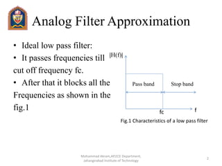
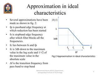
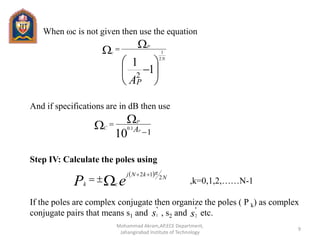
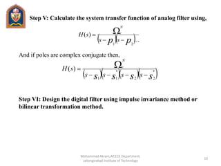
Designing of IIR Digital Filters
Butterworth Filter
1
Mohammad Akram,AP,ECE Department,
Jahangirabad Institute of Technology
Analog Filter Approximation
• Ideal low pass filter:
• It passes frequencies till
cut off frequency fc.
• After that it blocks all the
Frequencies as shown in the
fig.1 ffc
|H(f)|
Pass band Stop band
Fig.1 Characteristics of a low pass filter
2
Mohammad Akram,AP,ECE Department,
Jahangirabad Institute of Technology
Approximation in ideal
characteristics
• Several approximations have been
made as shown in fig. 2:
• fp is passband edge frequency at
which reduction has been started
• fs is stopband edge frequency
after which filter blocks all the
frequencies.
• fc lies between fs and fp
• fc is 3db down to the maximum
value in the log scale and 1/√2 of
the maximum value in the
absolute scale
• ∆f is the transition frequency from
pass band to stop band
Fig.2 Approximation in ideal characteristics
f
)( fH
-
3dB
1
fp fc fs
∆f
3
Mohammad Akram,AP,ECE Department,
Jahangirabad Institute of Technology
Butterworth Filter Approximation
• The magnitude response
of a butterworth filter is
shown in fig.3
• The magnitude
response of low pass
butterworth filter is
given by
1
Ap
0.5
As
Ωp Ωc Ωs Ω
Pass Band
Attenuation
Stop Band
Attenuation
Pass Band
Edge
Stop Band
Edge
Fig.3 Manitude response of low pass butterworth filter
2
)(H
4
Mohammad Akram,AP,ECE Department,
Jahangirabad Institute of Technology
Salient Features of low pass
Butterworth Filter
IH(Ω)I
Ω
1
1/√2
0
ΩC
Ideal Characteristics
N=2
N=4
N=8
Fig.4 Effect of N on the characteristics
•The magnitude response is
nearly constant(equal to 1) at
lower frequencies
•There are no ripples in
passband and stop band
•The maximum gain occurs at
Ω=0 and it is H(Ω)=1
•The magnitude response is
monotonically decreasing
•As the order of the filter ‘N’
increases, the response of the
filter is more close to the ideal
response 5
Mohammad Akram,AP,ECE Department,
Jahangirabad Institute of Technology
Designing using Butterworth
Approximation
•Design equation and design steps:
Let A p=Attenuation in passband
As=Attenuation in stop band
Ωp=Passband edge frequency
Ωc=Cut off frequency
Ωs=Stopband edge frequency
•In the problem the specifications of required digital filter is given and it
will be asked to design a particular discrete time butterworth filter.The
following steps should be used:
Step I:From the given specifications of digital filter, obtain equivalent
analog filter as follows:
(a) For Impulse Invariance method:
TS


6
Mohammad Akram,AP,ECE Department,
Jahangirabad Institute of Technology
(b) For bilinear transformation method:
Here Ω = Frequency of analog filter
ω=Frequency of digital filter
Ts = Sampling Time
Step II: Calculate the order N of filter using the equation,
2
tan
2 
TS

)log(
1
1
1
2
1
log
2
1
2









































P
S
PA
AS
N
7
Mohammad Akram,AP,ECE Department,
Jahangirabad Institute of Technology
If specifications are given in decibels(dB) then use the equation
Step III: Calculation of cut off frequency (Ωc)
The cut off frequency (Ωc) of analog filter is calculated as:
(a) For Impulse Invariance method:
For Bilinear Transformation method:





















P
S
dB
dB
A
A
N
P
S
log
1
1
log
2
1 10
10
)(1.0
)(1.0
TS
C
C

2
tan
2 C
S
C
T

8
Mohammad Akram,AP,ECE Department,
Jahangirabad Institute of Technology
When ωc is not given then use the equation
And if specifications are in dB then use
Step IV: Calculate the poles using
,k=0,1,2,……N-1
If the poles are complex conjugate then organize the poles ( P k) as complex
conjugate pairs that means s1 and , s2 and etc.







 
1
1
2
2
1
AP
N
P
c
110
1.0

  AP
P
C
 
eP N
kNj
ck
2
12 

s
*
1 s
*
2
9
Mohammad Akram,AP,ECE Department,
Jahangirabad Institute of Technology
Step V: Calculate the system transfer function of analog filter using,
And if poles are complex conjugate then,
Step VI: Design the digital filter using impulse invariance method or
bilinear transformation method.
  ...
)(
21
pp ss
sH
N
c

 
    ssss ssss
sH
N
c
*
22
*
11
)(

 
10
Mohammad Akram,AP,ECE Department,
Jahangirabad Institute of Technology
11
Mohammad Akram,AP,ECE Department,
Jahangirabad Institute of Technology

Butterworth filter

  • 1.
    Designing of IIRDigital Filters Butterworth Filter 1 Mohammad Akram,AP,ECE Department, Jahangirabad Institute of Technology
  • 2.
    Analog Filter Approximation •Ideal low pass filter: • It passes frequencies till cut off frequency fc. • After that it blocks all the Frequencies as shown in the fig.1 ffc |H(f)| Pass band Stop band Fig.1 Characteristics of a low pass filter 2 Mohammad Akram,AP,ECE Department, Jahangirabad Institute of Technology
  • 3.
    Approximation in ideal characteristics •Several approximations have been made as shown in fig. 2: • fp is passband edge frequency at which reduction has been started • fs is stopband edge frequency after which filter blocks all the frequencies. • fc lies between fs and fp • fc is 3db down to the maximum value in the log scale and 1/√2 of the maximum value in the absolute scale • ∆f is the transition frequency from pass band to stop band Fig.2 Approximation in ideal characteristics f )( fH - 3dB 1 fp fc fs ∆f 3 Mohammad Akram,AP,ECE Department, Jahangirabad Institute of Technology
  • 4.
    Butterworth Filter Approximation •The magnitude response of a butterworth filter is shown in fig.3 • The magnitude response of low pass butterworth filter is given by 1 Ap 0.5 As Ωp Ωc Ωs Ω Pass Band Attenuation Stop Band Attenuation Pass Band Edge Stop Band Edge Fig.3 Manitude response of low pass butterworth filter 2 )(H 4 Mohammad Akram,AP,ECE Department, Jahangirabad Institute of Technology
  • 5.
    Salient Features oflow pass Butterworth Filter IH(Ω)I Ω 1 1/√2 0 ΩC Ideal Characteristics N=2 N=4 N=8 Fig.4 Effect of N on the characteristics •The magnitude response is nearly constant(equal to 1) at lower frequencies •There are no ripples in passband and stop band •The maximum gain occurs at Ω=0 and it is H(Ω)=1 •The magnitude response is monotonically decreasing •As the order of the filter ‘N’ increases, the response of the filter is more close to the ideal response 5 Mohammad Akram,AP,ECE Department, Jahangirabad Institute of Technology
  • 6.
    Designing using Butterworth Approximation •Designequation and design steps: Let A p=Attenuation in passband As=Attenuation in stop band Ωp=Passband edge frequency Ωc=Cut off frequency Ωs=Stopband edge frequency •In the problem the specifications of required digital filter is given and it will be asked to design a particular discrete time butterworth filter.The following steps should be used: Step I:From the given specifications of digital filter, obtain equivalent analog filter as follows: (a) For Impulse Invariance method: TS   6 Mohammad Akram,AP,ECE Department, Jahangirabad Institute of Technology
  • 7.
    (b) For bilineartransformation method: Here Ω = Frequency of analog filter ω=Frequency of digital filter Ts = Sampling Time Step II: Calculate the order N of filter using the equation, 2 tan 2  TS  )log( 1 1 1 2 1 log 2 1 2                                          P S PA AS N 7 Mohammad Akram,AP,ECE Department, Jahangirabad Institute of Technology
  • 8.
    If specifications aregiven in decibels(dB) then use the equation Step III: Calculation of cut off frequency (Ωc) The cut off frequency (Ωc) of analog filter is calculated as: (a) For Impulse Invariance method: For Bilinear Transformation method:                      P S dB dB A A N P S log 1 1 log 2 1 10 10 )(1.0 )(1.0 TS C C  2 tan 2 C S C T  8 Mohammad Akram,AP,ECE Department, Jahangirabad Institute of Technology
  • 9.
    When ωc isnot given then use the equation And if specifications are in dB then use Step IV: Calculate the poles using ,k=0,1,2,……N-1 If the poles are complex conjugate then organize the poles ( P k) as complex conjugate pairs that means s1 and , s2 and etc.          1 1 2 2 1 AP N P c 110 1.0    AP P C   eP N kNj ck 2 12   s * 1 s * 2 9 Mohammad Akram,AP,ECE Department, Jahangirabad Institute of Technology
  • 10.
    Step V: Calculatethe system transfer function of analog filter using, And if poles are complex conjugate then, Step VI: Design the digital filter using impulse invariance method or bilinear transformation method.   ... )( 21 pp ss sH N c        ssss ssss sH N c * 22 * 11 )(    10 Mohammad Akram,AP,ECE Department, Jahangirabad Institute of Technology
  • 11.