Downloaded 555 times

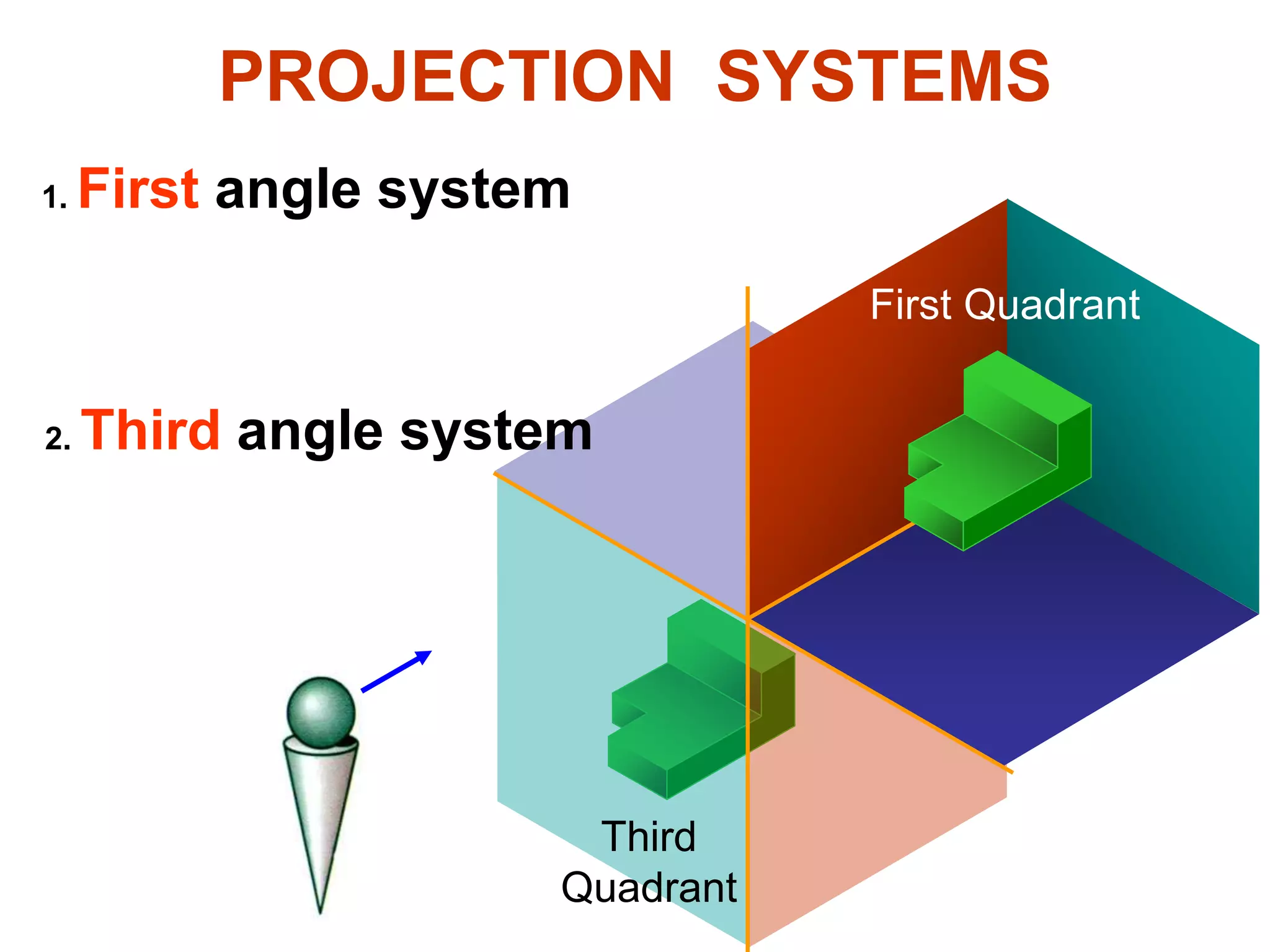
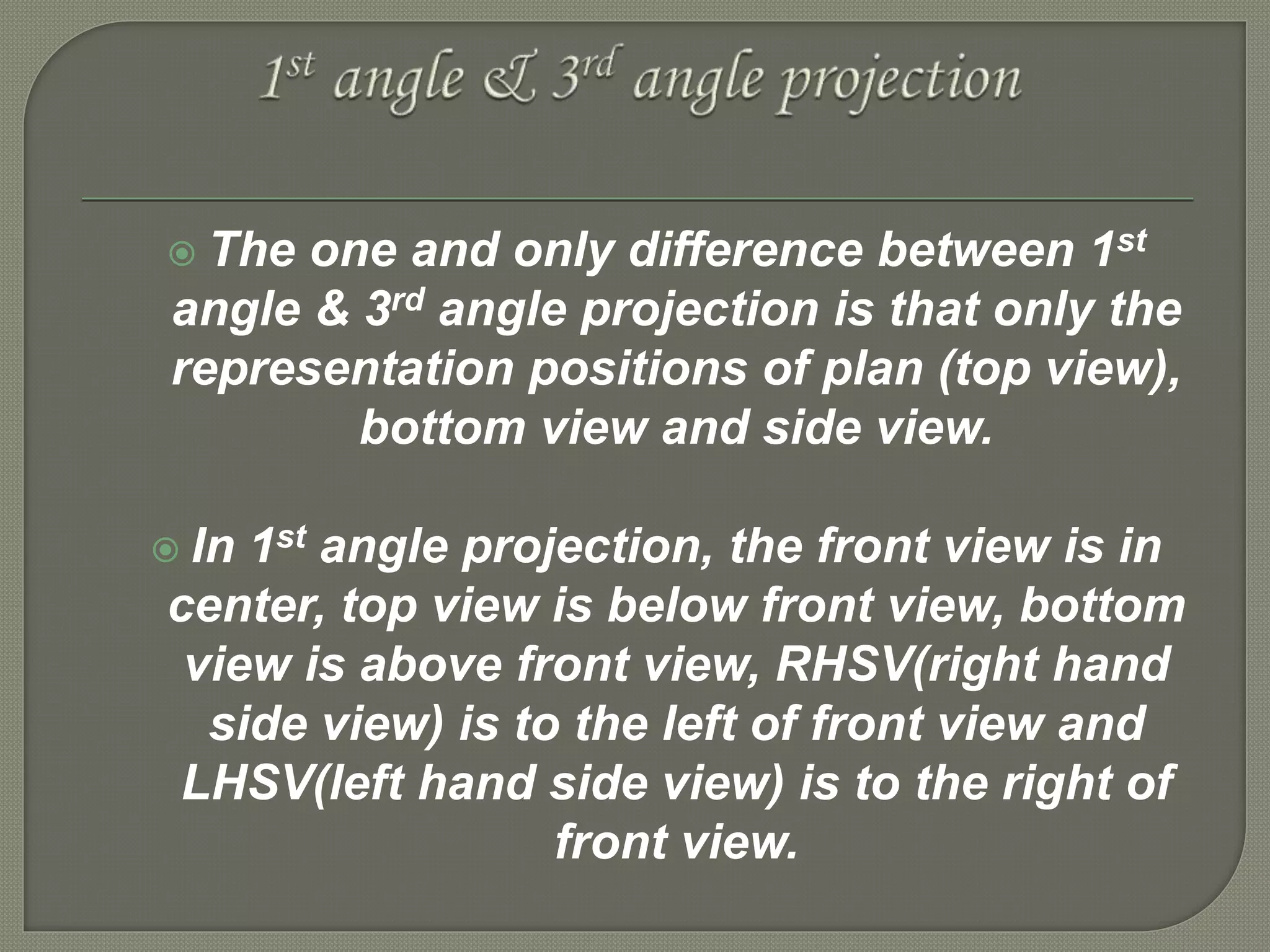

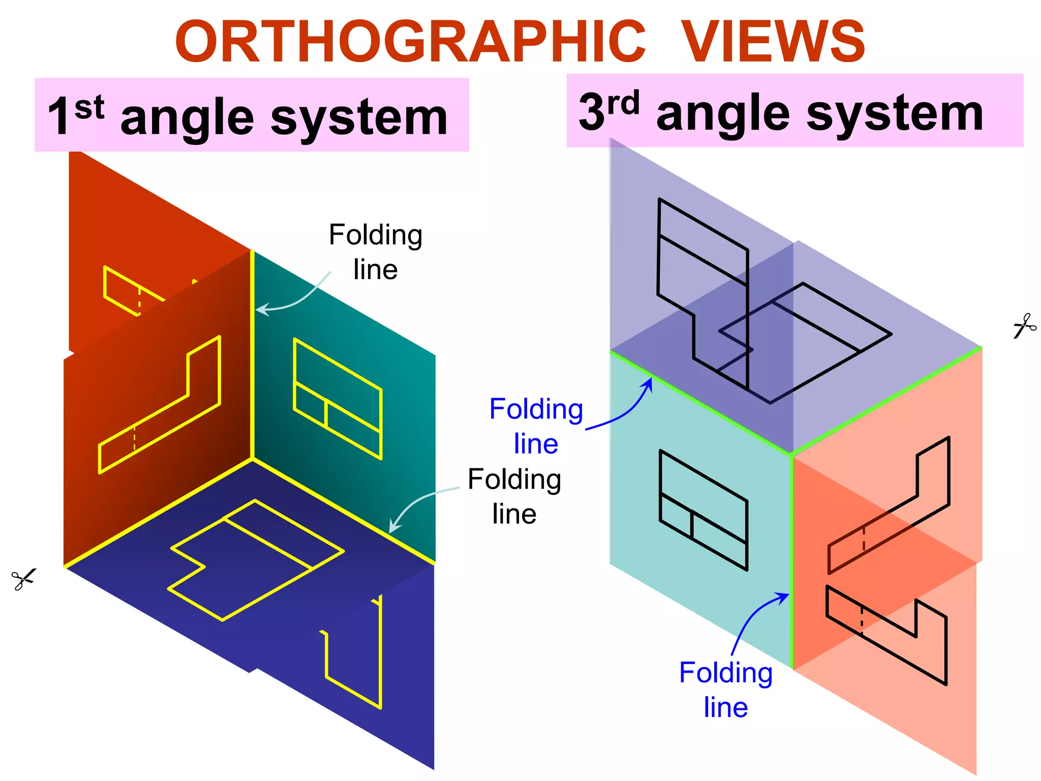
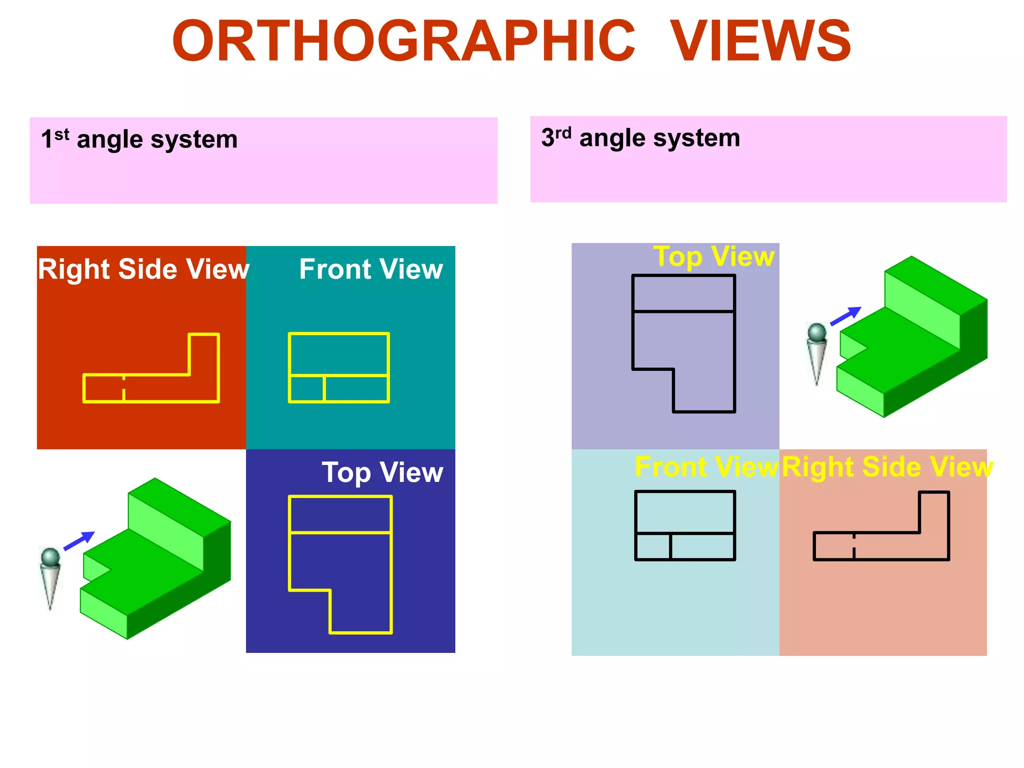
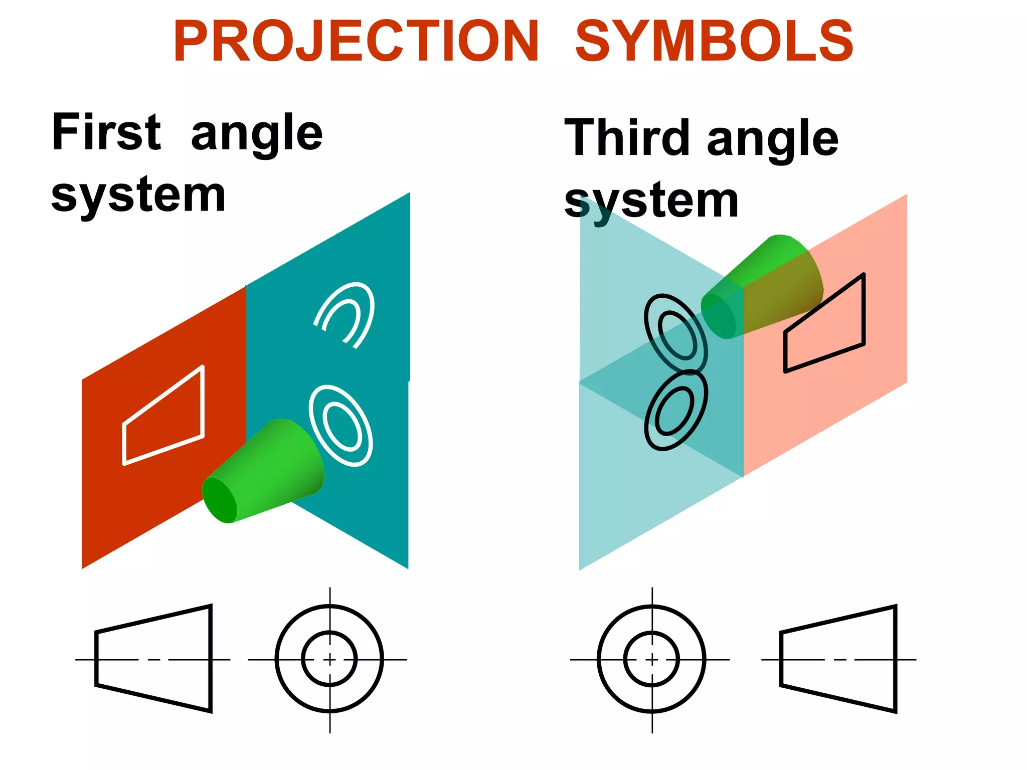
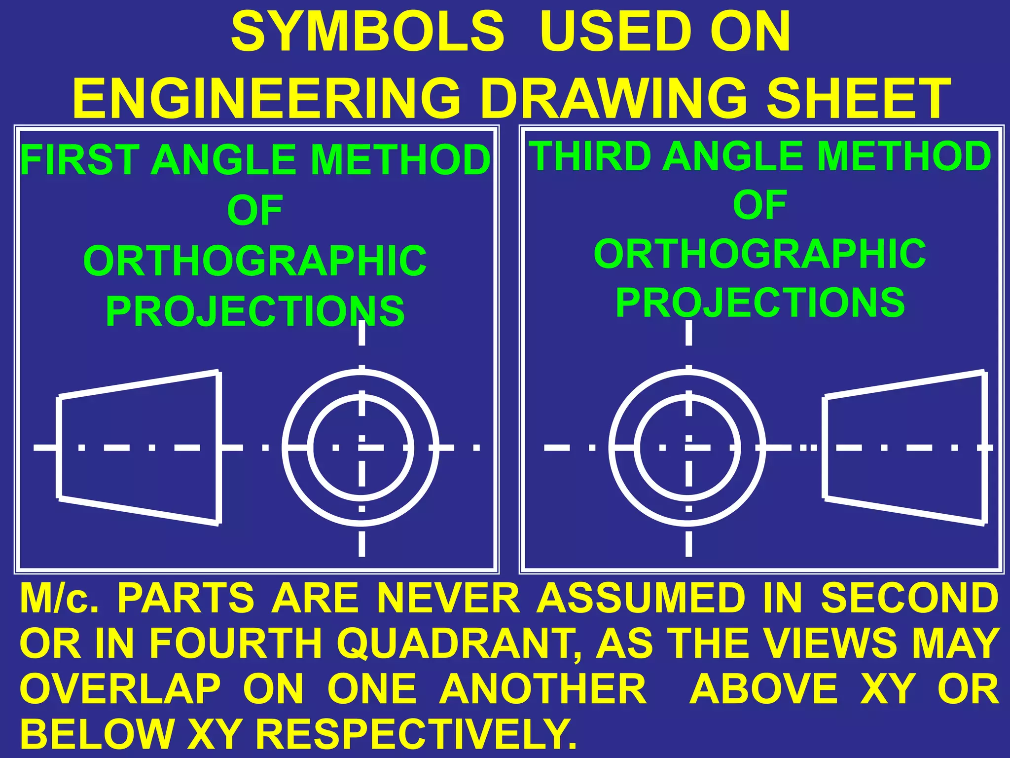
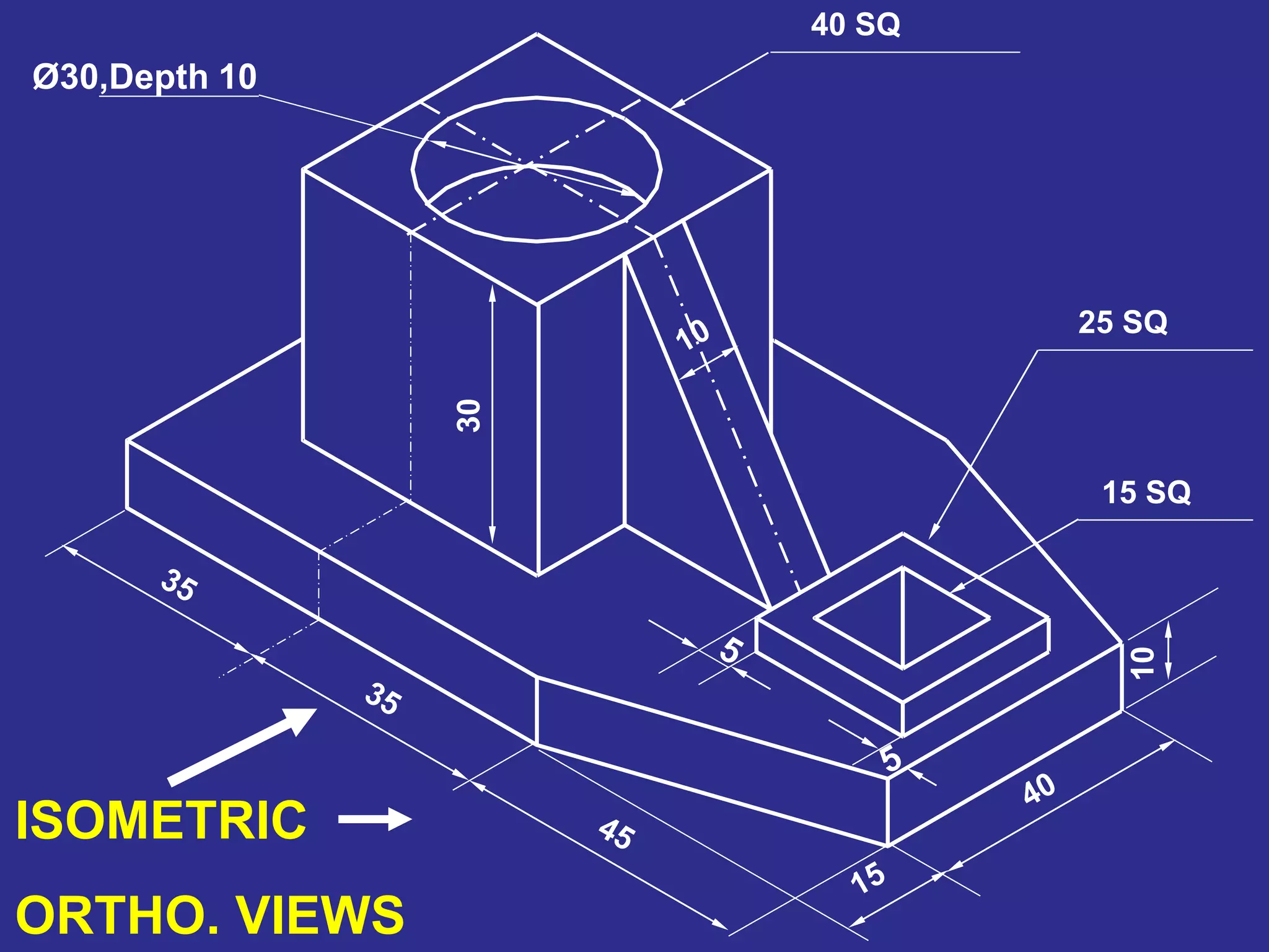
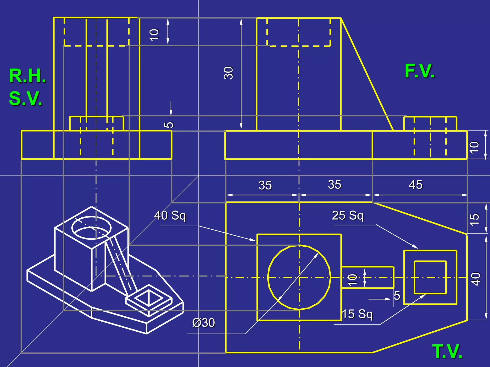

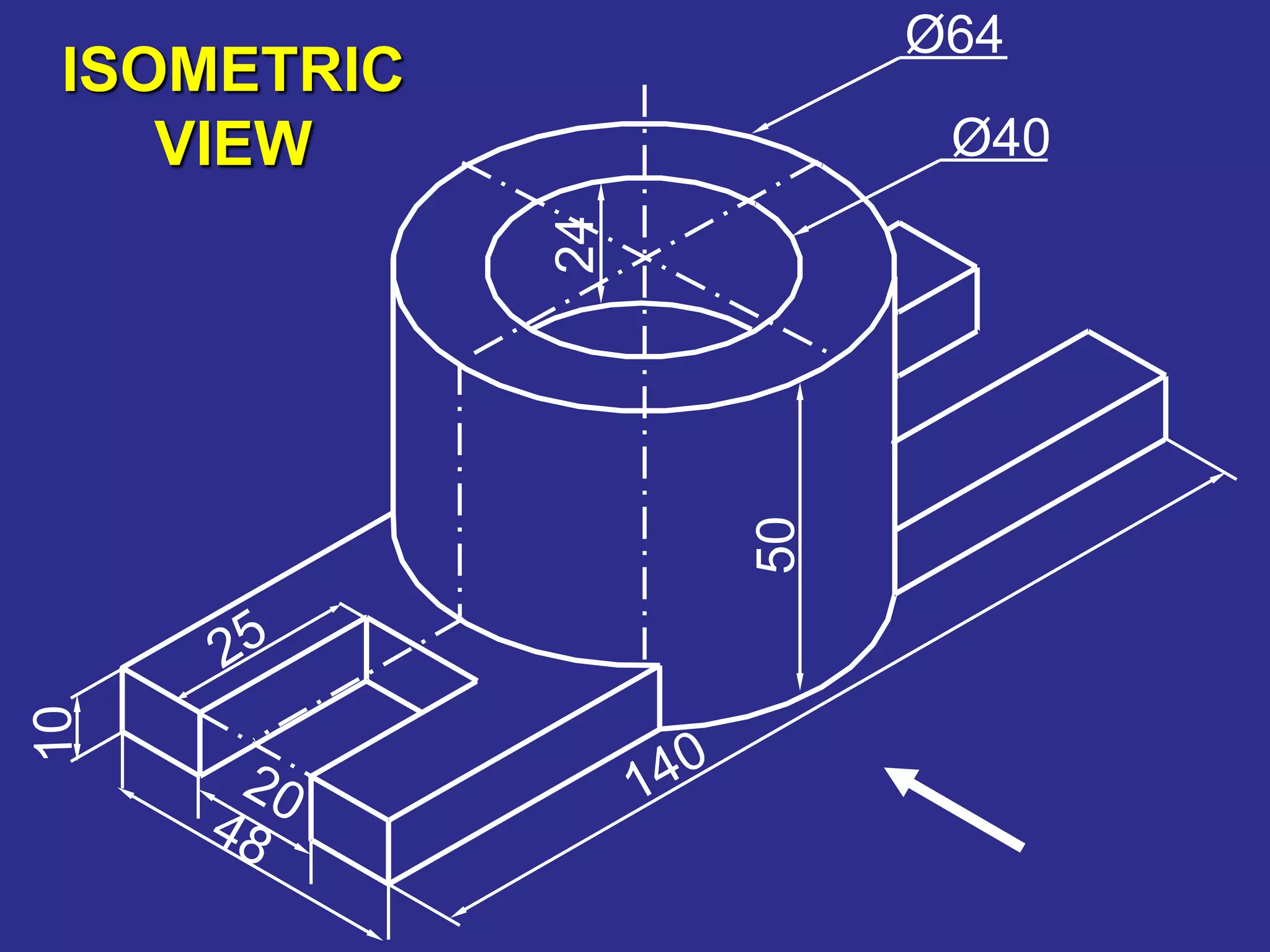
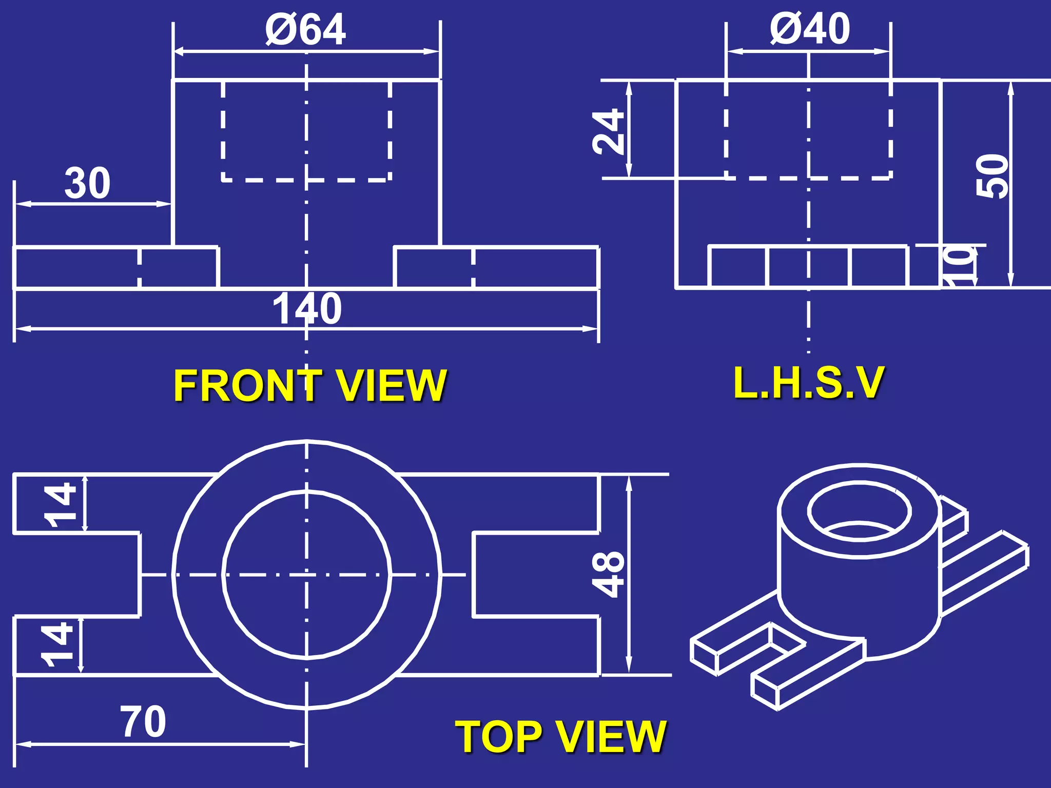
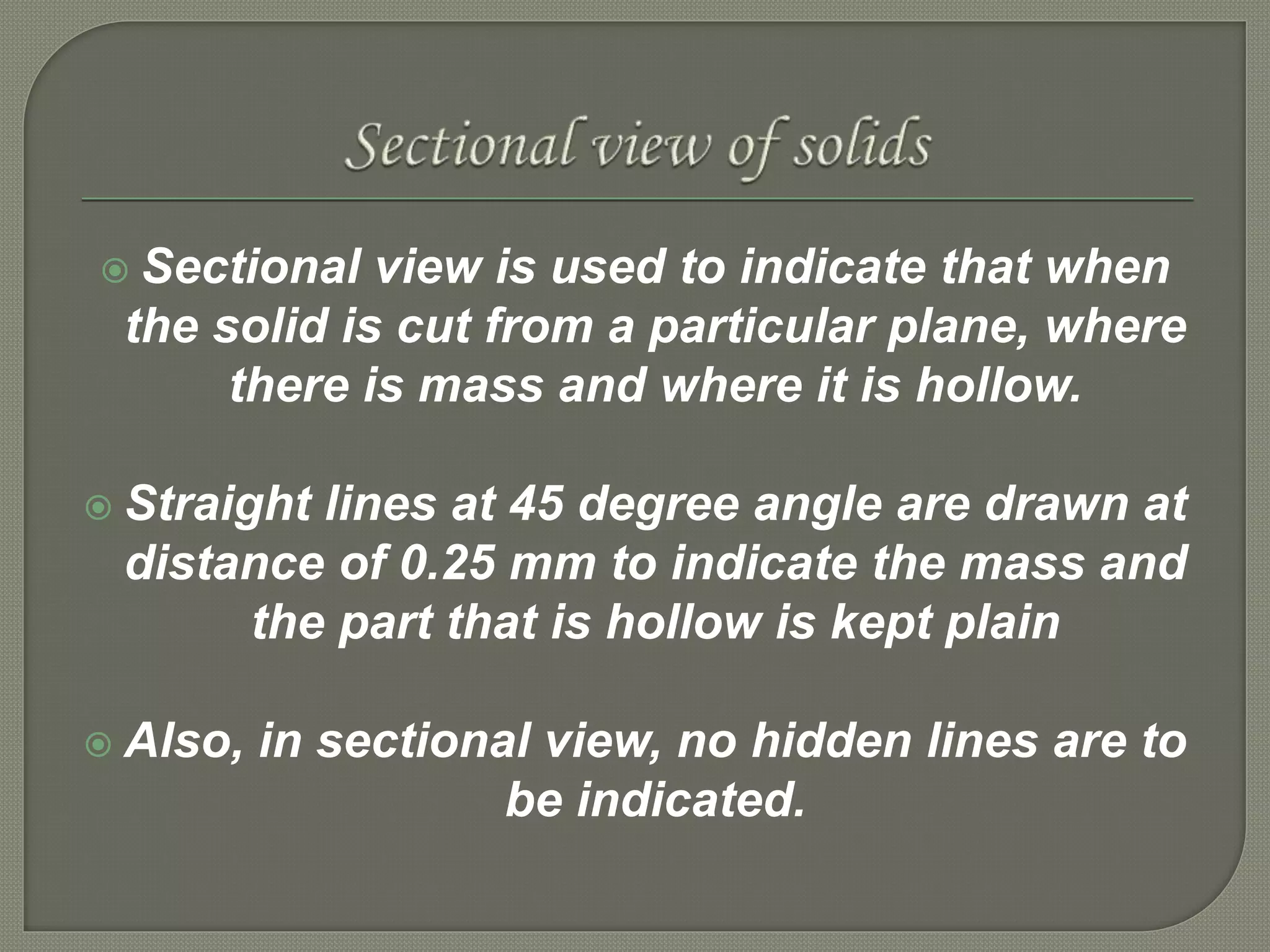
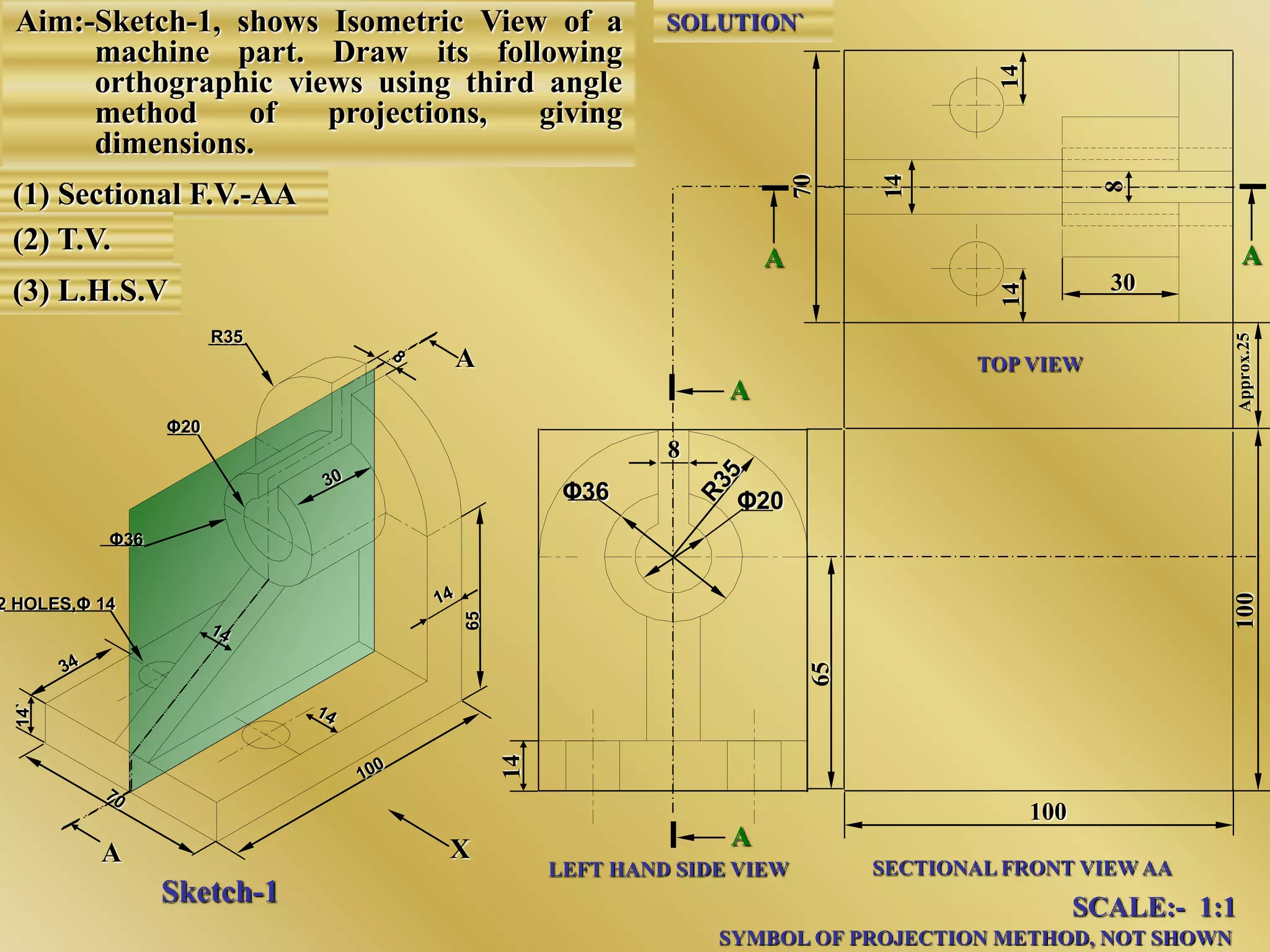
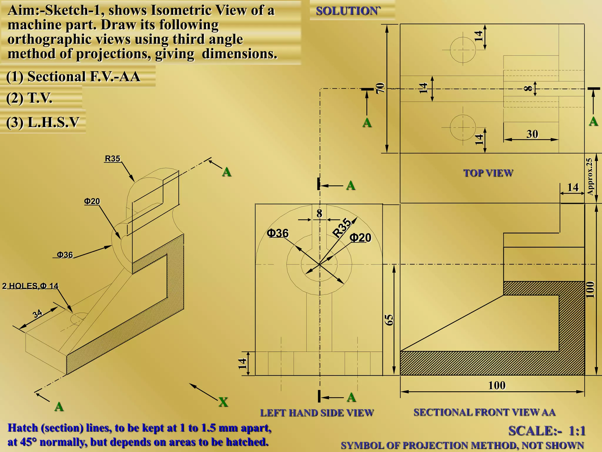
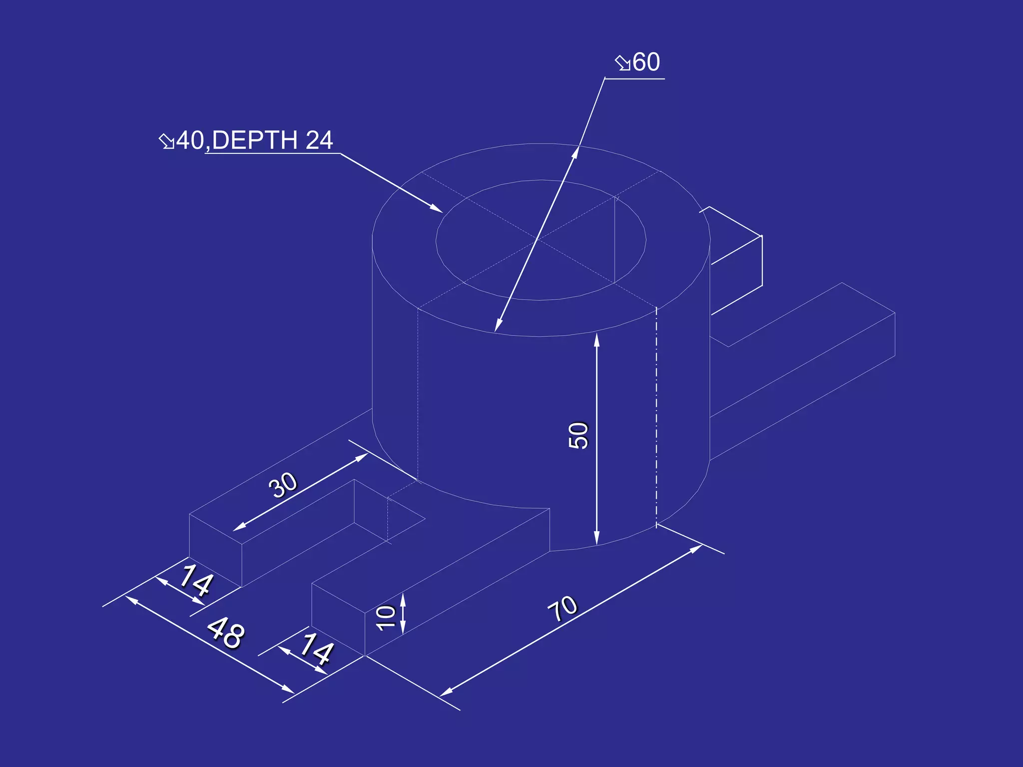


The document discusses orthographic projections and sectional orthographic projections. It explains that orthographic projections create 2D representations of 3D objects by projecting lines from edges orthogonal to the projection plane. There are two types of projections: first angle and third angle. The difference between them is the positioning of top, bottom, and side views. Sectional views indicate hollow and solid areas using hatching lines at 45 degrees spaced 0.25 mm apart. The document provides examples of orthographic and sectional orthographic projections of various machine parts.


![Ortographicprojection(thedirectdata[1].com)](https://cdn.slidesharecdn.com/ss_thumbnails/ortographicprojectionthedirectdata1-170802182401-thumbnail.jpg?width=640&height=640&fit=bounds)


