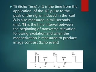
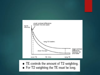
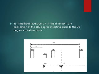
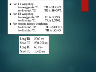
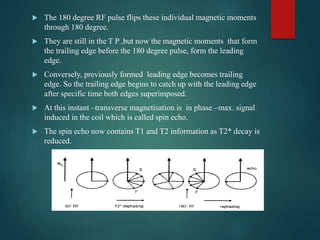
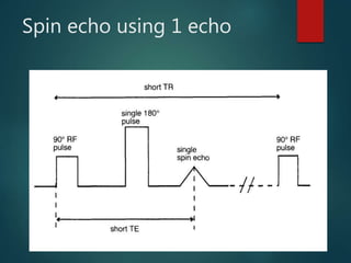
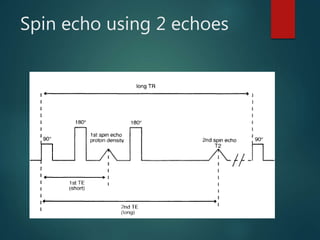
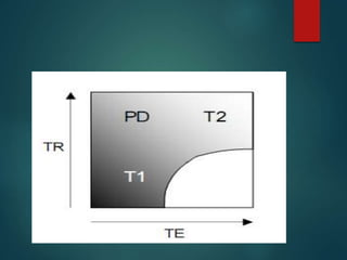
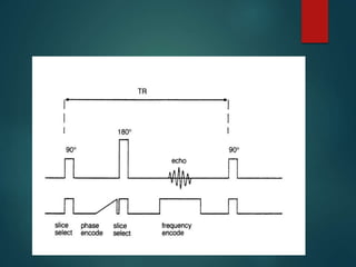
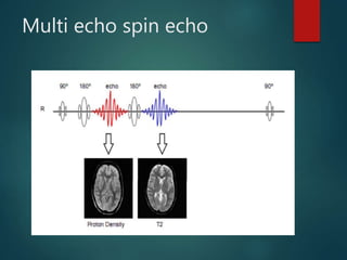
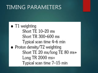
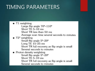
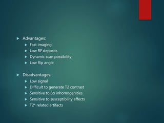
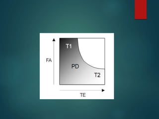
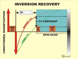
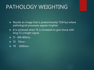
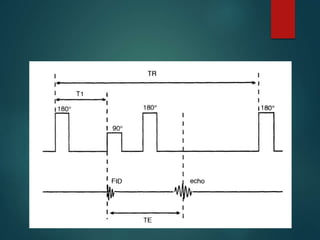
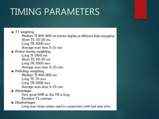
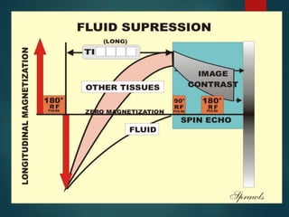
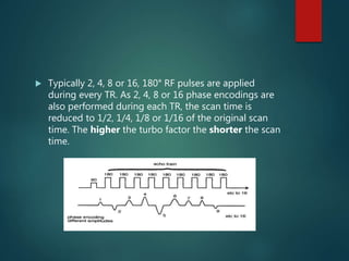
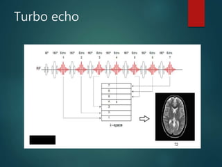
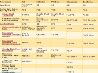
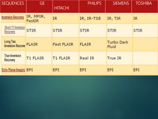
BASIC PULSE
SEQUENCES IN MRI
UPAKAR PAUDEL (B.SC MIT )
UCMSTH BHAIRAHAWA
INTRODUCTON
 A pulse sequence is a sequence of events, which are
needed to acquire MRI images. These events are: RF
pulses, gradient switches and signal collecting.
 The way in which the RF coil & gradient fields are
turned on & off is called pulse sequences.
 What kind of image contrast we want to see and kind
of pathology we want to detect is determined by the
pulse sequence used.
 The basic MRI pulse sequences are
 Spin echo pulse sequence
 Gradient echo pulse sequence
BASIC PARAMETERS
 TR (Repetition time) :- It is the time
from the application of one RF pulse
to the application of next RF & is
measured in milliseconds (ms).( usually
time between two (90 degree pulses)
 TE (Echo Time) :- It is the time from the
application of the RF pulse to the
peak of the signal induced in the coil
& is also measured in milliseconds
(ms). TE is the time interval between
the beginning of transverse relaxation
following excitation and when the
magnetization is measured to produce
image contrast (Echo event)
 TI (Time from Inversion) : It is the time from the
application of the 180 degree inverting pulse to the 90
degree excitation pulse.
Multi Slicing
 The average time per slice is significantly reduced using multiple
slice acquisition methods. Several slices within the tissue volume
are selectively excited during a TR interval to fully utilize the
(dead) time waiting for longitudinal recovery in a specific slice .
 The total number of slices is a function ofTR, TE, and machine
limitations:
Total no of slices =
TR/(TE+C)
where C is a constant dependent on the MR equipment capabilities
(computer speed, gradient capabilities, RF cycling, etc.).
 Long TR acquisitions such as proton density and T2-weighted
sequences provide a greater number of slices than T1 weighted
sequences with a short TR. The chief trade-off is a loss of tissue
contrast due to cross-excitation of adjacent slices, causing
undesired spin saturation.
SPIN ECHO
 It has at least two RF pulses, an excitation pulse and
one or more 180° refocusing pulses that generate the
spin echo.
 Utilizes 90 degree excitation pulse to flip the NMV into
transverse plane.NMV precesses in the Transverse
Plane induces voltage in the receiver coil.
 When the 90 degree RF pulse is removed an FID signal
is produced, T2 * dephasing occurs immediately & the
signal decays.
 A 180 degree RF pulse is then used to compensate
this dephasing.
 The 180 degree RF pulse flips these individual magnetic moments
through 180 degree.
 They are still in the T P ,but now the magnetic moments that form
the trailing edge before the 180 degree pulse, form the leading
edge.
 Conversely, previously formed leading edge becomes trailing
edge. So the trailing edge begins to catch up with the leading edge
after specific time both edges superimposed.
 At this instant –transverse magnetisation is in phase –max. signal
induced in the coil which is called spin echo.
 The spin echo now contains T1 and T2 information as T2* decay is
reduced.
Spin echo using 1 echo
Spin echo using 2 echoes
Multi echo spin echo
TIMING PARAMETERS
Advantages
 Good image quality
 Very versatile
 True T2 weighting
 Available on all systems
 Gold standard for image contrast and
weighting
Disadvantage
 Long scan times
GRADIENT ECHO
 The gradient echo pulse sequence is the simplest type of
MRI sequence.
 The major purpose behind the gradient technique is a
significant reduction in scan time
 Small flip angle are employed, which in turn allow very
short repetition time thus decreasing the scan time.
 The gradient echo is generated by the frequency encode
gradient, except that it is used twice in succession and in
opposite direction : it is used in reverse at first to enforce
transverse dephasement of spinning protons and then
right after , it is used as a readout gradient to realign the
dephased protons and hence acquired signals.
 There is absence of 180 degree RF pulse in gradient
echo sequence
 Does not compensate for T2* effect
 Increased sensitivity to T2* effect as there is lack of 180
degree refocusing pulse
Dephasing And Phasing
TIMING PARAMETERS
 Advantages:
 Fast imaging
 Low RF deposits
 Dynamic scan possibility
 Low flip angle
 Disadvantages:
 Low signal
 Difficult to generate T2 contrast
 Sensitive to Bo inhomogenities
 Sensitive to susceptibility effects
 T2* related artifacts
INVERSION RECOVERY
 In inversion recovery first 180 degree RF pulse is applied
which flip the magnetization vector in 180 degree i.e. –Z
direction.
 There is no magnetization in the x-y plane yet
 After the 180 degree pulse there is only T1 recovery
going on because there is no component in the x-y plane
and therefore no T2 relaxation
 The T1 relaxation process would take place twice as long
as when the net magnetization would have been flipped
to x-y plane.
 T1 relaxation is allowed to happen for certain time, known
as the inversion time (TI) after that normal SE sequence is
applied
• After a time TI , we apply the 90 degree pulse which flips the
longitudinal magnetization into the x-y plane the contrast on the
image depends on the amounts of longitudinal recovery of each
vector
• If the excitation pulse is applied after the NMV has relaxed back
through the transverse plane , the contrast will depend on the
amount of longitudinal relaxation of each vector (like in spin echo)
• The resultant image is highly T1 weighted as the 180 degree pulse
causes full saturation ensuring a large contrast between tissues.T1
WEIGHTIN
G
 If the 90 degree excitation pulse is not applied until
the NMV had reached full recovery , a proton density
weighted image results, as both fat and water have
fully relaxed
PD
WEIGHTING
PATHOLOGY WEIGHTING
 Results an image that is predominantly T1W but where
pathological processes appear brighter.
 It is achieved when TE is increased to give tissue with
long T2 a bright signal.
 TI 400-800ms.
 TE 70ms+
 TR 2000ms+
TIMING PARAMETERS
FLAIR
 Fluid attenuated inversion recovery (FLAIR)is an special
inversion recovery sequence with long TI to remove the
effect of fluids from the resultant images
 The signal from CSF is nulled by selecting TI
corresponding to the time of recovery of CSF from180
degree to the transverse plane and there is no
longitudinal magnetisetion present in CSF . When the 90
degree excitation pulse is applied the CSF vector is
flipped into full saturation. So signal from CSF is nulled (
as no transverse comp)
 It is used to suppress the CSF signal in T2 & proton
density images. So pathology adjacent to the CSF is seen
more clearly
 A TI of 1700-2200 ms achieves CSF suppression
 This type of sequence is particularly useful in the
detection of subtle changes at the periphery of the
hemispheres and in the periventricular region close to
CSF.
 The usefulness of FLAIR sequences has been evaluated
in diseases of the central nervous system such as :
 infarction
 multiple sclerosis
 subarachnoid hemorrhage
 head injuries, and others.
TIMING PARAMETERS
STIR
 Short Tau Inversion Recovery is an IR pulse sequence
that uses a short TI that corresponding to the time it
takes fat to recover from full inversion to transverse
plane.
 It is used to achieve suppression of fat in T1 weighted
image
 Inversion time is calculated as TI=T1ln2
 For fat the inversion time is approximately 140ms at
1.5T
TIMING PARAMETERS
FAST SPIN ECHO
 Fast spin echo (FSE) is a much faster version of
conventional spin echo. In spin echo sequences, one
phase encoding only is performed during each TR .
The scan time is a function of TR, NEX and phase
encodings.
 One of the ways of speeding up a conventional
sequence is to reduce the number of phase encoding
steps. However this normally results in a loss of
resolution.
 FSE overcomes this by still performing the same
number of phase encodings, thereby maintaining
resolution, but more than one phase encoding is
performed per TR, reducing the scan time.
 FSE employs a train of 180° rephasing pulses, each one
producing a spin echo. This train of spin echoes is
called an echo train. The number of 180° RF pulses
and resultant echoes is called the echo train
length(ETL) or turbo factor. The spacing between
each echo is called the echo spacing.
 After each rephasing, a phase encoding step is
performed and data from the resultant echo are stored
in K space . Therefore several lines of K space are filled
every TR instead of one line as in conventional spin
echo. As K space is filled more rapidly, the scan time
decreases.
 Typically 2, 4, 8 or 16, 180° RF pulses are applied
during every TR. As 2, 4, 8 or 16 phase encodings are
also performed during each TR, the scan time is
reduced to 1/2, 1/4, 1/8 or 1/16 of the original scan
time. The higher the turbo factor the shorter the scan
time.
Turbo echo
TIMING PARAMETERS
 Advantages:
 Short scan times
 High resolution imaging
 Increased T2 weighting
 Excellent contrast betn tissues & still fluids
 Very fast: useful for moving organs.
 Low sensitivity to magnetic susceptibility artifacts
 Disadvantages:
 Some flow artefacts increased
 Incompatible with some imaging options
 Some contrast interpretation problems
 Image blurring possible
fat remains bright in t2 weighted image.
Fast Advanced Spin Echo
(FASE)
SINGLE SHOT FSE
 This is the combination of FSE with partial Fourier
technique.
 Half of lines of k-space are acquired in one TR and the
other half are interpolated.
 Reduction in imaging time as all of the image data is
acquired in one TR.
 However it’s disadvantage is SNR is low.
3D FSE
 It is achieved by the excitation of slab as opposed to
single slice.
 Helps in Acquisition of high resolution T2W image.
 Single breath-hold volume acquisition of the liver and
for MRCP.
 Less susceptibility artefact than conventional 3D
gradient echo.
CSE V/S FSE
 Fat remains bright on T2W image in FSE.
 Muscle appear darker on FSE than CSE
 Multiple 180 degree pulses reduce the magnetic
susceptibility effect in FSE
 Artefact from metal implant is significantly reduced
using fast SE.
 The TR of fast SE is much longer than CSE.
STEADY STATE
 Stage where the TR is shorter than the T1 and T2 times
of the tissue.
 Flip angles of 30 degree- 45 degree and TR of 20-50
ms achieves this state
 No times for the transverse magnetization to decay
before the pulse sequence is achieved so there is
coexistence of both longitudinal and transverse
magnetization
Residual transverse
magnetisetion
 The transverse magnetization produced as a result of
previous excitations is called the residual transverse
magnetization(RTM)
 The RTM affects the contrast as it results in tissues with
long T2 times appearing bright on the image
 Gradient echo sequence are classified whether the
RTM is in phase(coherent) or out of phase(incoherent)
 RTM is kept coherent by a processes know as
rewinding
Rewinding
 It is the process by residual transverse magnetization is
kept coherent
 Achieved by reversing the slope of the phase encoding
gradient after readout
 Results in RTM rephasing so that it is in phase at the
beginning of the next repetition
 This allows rtm to build up so that tissues with a long
T2 produce high signal
SEQUENCES GE
HITACHI
PHILIPS SIEMENS TOSHIBA
REFERENCES
 MRI in Practice : Catherine Westbrook and Carolyn
Kaut.
 MRI Made Easy :Prof. Dr. Hans H. Schild
 The Essentials of Medical Imaging : Jerrold T. Bushberg
 Contrast mechanism and pulse sequences : Allen W.
Song
 MRI pulse sequences : Jerry Allison
THANK YOU !!

Basic Pulse Sequences In MRI

  • 1.
    BASIC PULSE SEQUENCES INMRI UPAKAR PAUDEL (B.SC MIT ) UCMSTH BHAIRAHAWA
  • 2.
    INTRODUCTON  A pulsesequence is a sequence of events, which are needed to acquire MRI images. These events are: RF pulses, gradient switches and signal collecting.  The way in which the RF coil & gradient fields are turned on & off is called pulse sequences.  What kind of image contrast we want to see and kind of pathology we want to detect is determined by the pulse sequence used.
  • 3.
     The basicMRI pulse sequences are  Spin echo pulse sequence  Gradient echo pulse sequence
  • 4.
    BASIC PARAMETERS  TR(Repetition time) :- It is the time from the application of one RF pulse to the application of next RF & is measured in milliseconds (ms).( usually time between two (90 degree pulses)
  • 6.
     TE (EchoTime) :- It is the time from the application of the RF pulse to the peak of the signal induced in the coil & is also measured in milliseconds (ms). TE is the time interval between the beginning of transverse relaxation following excitation and when the magnetization is measured to produce image contrast (Echo event)
  • 8.
     TI (Timefrom Inversion) : It is the time from the application of the 180 degree inverting pulse to the 90 degree excitation pulse.
  • 10.
  • 11.
     The averagetime per slice is significantly reduced using multiple slice acquisition methods. Several slices within the tissue volume are selectively excited during a TR interval to fully utilize the (dead) time waiting for longitudinal recovery in a specific slice .  The total number of slices is a function ofTR, TE, and machine limitations: Total no of slices = TR/(TE+C) where C is a constant dependent on the MR equipment capabilities (computer speed, gradient capabilities, RF cycling, etc.).  Long TR acquisitions such as proton density and T2-weighted sequences provide a greater number of slices than T1 weighted sequences with a short TR. The chief trade-off is a loss of tissue contrast due to cross-excitation of adjacent slices, causing undesired spin saturation.
  • 13.
    SPIN ECHO  Ithas at least two RF pulses, an excitation pulse and one or more 180° refocusing pulses that generate the spin echo.  Utilizes 90 degree excitation pulse to flip the NMV into transverse plane.NMV precesses in the Transverse Plane induces voltage in the receiver coil.  When the 90 degree RF pulse is removed an FID signal is produced, T2 * dephasing occurs immediately & the signal decays.  A 180 degree RF pulse is then used to compensate this dephasing.
  • 14.
     The 180degree RF pulse flips these individual magnetic moments through 180 degree.  They are still in the T P ,but now the magnetic moments that form the trailing edge before the 180 degree pulse, form the leading edge.  Conversely, previously formed leading edge becomes trailing edge. So the trailing edge begins to catch up with the leading edge after specific time both edges superimposed.  At this instant –transverse magnetisation is in phase –max. signal induced in the coil which is called spin echo.  The spin echo now contains T1 and T2 information as T2* decay is reduced.
  • 16.
  • 17.
  • 20.
  • 21.
  • 22.
    Advantages  Good imagequality  Very versatile  True T2 weighting  Available on all systems  Gold standard for image contrast and weighting Disadvantage  Long scan times
  • 24.
    GRADIENT ECHO  Thegradient echo pulse sequence is the simplest type of MRI sequence.  The major purpose behind the gradient technique is a significant reduction in scan time  Small flip angle are employed, which in turn allow very short repetition time thus decreasing the scan time.  The gradient echo is generated by the frequency encode gradient, except that it is used twice in succession and in opposite direction : it is used in reverse at first to enforce transverse dephasement of spinning protons and then right after , it is used as a readout gradient to realign the dephased protons and hence acquired signals.
  • 25.
     There isabsence of 180 degree RF pulse in gradient echo sequence  Does not compensate for T2* effect  Increased sensitivity to T2* effect as there is lack of 180 degree refocusing pulse
  • 26.
  • 30.
  • 31.
     Advantages:  Fastimaging  Low RF deposits  Dynamic scan possibility  Low flip angle  Disadvantages:  Low signal  Difficult to generate T2 contrast  Sensitive to Bo inhomogenities  Sensitive to susceptibility effects  T2* related artifacts
  • 34.
    INVERSION RECOVERY  Ininversion recovery first 180 degree RF pulse is applied which flip the magnetization vector in 180 degree i.e. –Z direction.  There is no magnetization in the x-y plane yet  After the 180 degree pulse there is only T1 recovery going on because there is no component in the x-y plane and therefore no T2 relaxation  The T1 relaxation process would take place twice as long as when the net magnetization would have been flipped to x-y plane.  T1 relaxation is allowed to happen for certain time, known as the inversion time (TI) after that normal SE sequence is applied
  • 35.
    • After atime TI , we apply the 90 degree pulse which flips the longitudinal magnetization into the x-y plane the contrast on the image depends on the amounts of longitudinal recovery of each vector • If the excitation pulse is applied after the NMV has relaxed back through the transverse plane , the contrast will depend on the amount of longitudinal relaxation of each vector (like in spin echo) • The resultant image is highly T1 weighted as the 180 degree pulse causes full saturation ensuring a large contrast between tissues.T1 WEIGHTIN G
  • 37.
     If the90 degree excitation pulse is not applied until the NMV had reached full recovery , a proton density weighted image results, as both fat and water have fully relaxed PD WEIGHTING
  • 39.
    PATHOLOGY WEIGHTING  Resultsan image that is predominantly T1W but where pathological processes appear brighter.  It is achieved when TE is increased to give tissue with long T2 a bright signal.  TI 400-800ms.  TE 70ms+  TR 2000ms+
  • 41.
  • 43.
    FLAIR  Fluid attenuatedinversion recovery (FLAIR)is an special inversion recovery sequence with long TI to remove the effect of fluids from the resultant images  The signal from CSF is nulled by selecting TI corresponding to the time of recovery of CSF from180 degree to the transverse plane and there is no longitudinal magnetisetion present in CSF . When the 90 degree excitation pulse is applied the CSF vector is flipped into full saturation. So signal from CSF is nulled ( as no transverse comp)  It is used to suppress the CSF signal in T2 & proton density images. So pathology adjacent to the CSF is seen more clearly  A TI of 1700-2200 ms achieves CSF suppression
  • 44.
     This typeof sequence is particularly useful in the detection of subtle changes at the periphery of the hemispheres and in the periventricular region close to CSF.  The usefulness of FLAIR sequences has been evaluated in diseases of the central nervous system such as :  infarction  multiple sclerosis  subarachnoid hemorrhage  head injuries, and others.
  • 45.
  • 47.
    STIR  Short TauInversion Recovery is an IR pulse sequence that uses a short TI that corresponding to the time it takes fat to recover from full inversion to transverse plane.  It is used to achieve suppression of fat in T1 weighted image  Inversion time is calculated as TI=T1ln2  For fat the inversion time is approximately 140ms at 1.5T
  • 48.
  • 50.
    FAST SPIN ECHO Fast spin echo (FSE) is a much faster version of conventional spin echo. In spin echo sequences, one phase encoding only is performed during each TR . The scan time is a function of TR, NEX and phase encodings.  One of the ways of speeding up a conventional sequence is to reduce the number of phase encoding steps. However this normally results in a loss of resolution.  FSE overcomes this by still performing the same number of phase encodings, thereby maintaining resolution, but more than one phase encoding is performed per TR, reducing the scan time.
  • 51.
     FSE employsa train of 180° rephasing pulses, each one producing a spin echo. This train of spin echoes is called an echo train. The number of 180° RF pulses and resultant echoes is called the echo train length(ETL) or turbo factor. The spacing between each echo is called the echo spacing.  After each rephasing, a phase encoding step is performed and data from the resultant echo are stored in K space . Therefore several lines of K space are filled every TR instead of one line as in conventional spin echo. As K space is filled more rapidly, the scan time decreases.
  • 52.
     Typically 2,4, 8 or 16, 180° RF pulses are applied during every TR. As 2, 4, 8 or 16 phase encodings are also performed during each TR, the scan time is reduced to 1/2, 1/4, 1/8 or 1/16 of the original scan time. The higher the turbo factor the shorter the scan time.
  • 53.
  • 55.
  • 56.
     Advantages:  Shortscan times  High resolution imaging  Increased T2 weighting  Excellent contrast betn tissues & still fluids  Very fast: useful for moving organs.  Low sensitivity to magnetic susceptibility artifacts  Disadvantages:  Some flow artefacts increased  Incompatible with some imaging options  Some contrast interpretation problems  Image blurring possible fat remains bright in t2 weighted image.
  • 57.
    Fast Advanced SpinEcho (FASE)
  • 58.
    SINGLE SHOT FSE This is the combination of FSE with partial Fourier technique.  Half of lines of k-space are acquired in one TR and the other half are interpolated.  Reduction in imaging time as all of the image data is acquired in one TR.  However it’s disadvantage is SNR is low.
  • 59.
    3D FSE  Itis achieved by the excitation of slab as opposed to single slice.  Helps in Acquisition of high resolution T2W image.  Single breath-hold volume acquisition of the liver and for MRCP.  Less susceptibility artefact than conventional 3D gradient echo.
  • 60.
    CSE V/S FSE Fat remains bright on T2W image in FSE.  Muscle appear darker on FSE than CSE  Multiple 180 degree pulses reduce the magnetic susceptibility effect in FSE  Artefact from metal implant is significantly reduced using fast SE.  The TR of fast SE is much longer than CSE.
  • 61.
    STEADY STATE  Stagewhere the TR is shorter than the T1 and T2 times of the tissue.  Flip angles of 30 degree- 45 degree and TR of 20-50 ms achieves this state  No times for the transverse magnetization to decay before the pulse sequence is achieved so there is coexistence of both longitudinal and transverse magnetization
  • 63.
    Residual transverse magnetisetion  Thetransverse magnetization produced as a result of previous excitations is called the residual transverse magnetization(RTM)  The RTM affects the contrast as it results in tissues with long T2 times appearing bright on the image  Gradient echo sequence are classified whether the RTM is in phase(coherent) or out of phase(incoherent)  RTM is kept coherent by a processes know as rewinding
  • 64.
    Rewinding  It isthe process by residual transverse magnetization is kept coherent  Achieved by reversing the slope of the phase encoding gradient after readout  Results in RTM rephasing so that it is in phase at the beginning of the next repetition  This allows rtm to build up so that tissues with a long T2 produce high signal
  • 66.
  • 67.
    REFERENCES  MRI inPractice : Catherine Westbrook and Carolyn Kaut.  MRI Made Easy :Prof. Dr. Hans H. Schild  The Essentials of Medical Imaging : Jerrold T. Bushberg  Contrast mechanism and pulse sequences : Allen W. Song  MRI pulse sequences : Jerry Allison
  • 68.

Editor's Notes

  • #12 The average acquisition time per slice in a single-slice spin echo sequence is clinically unacceptable.
  • #25 A small flip angle (α) minimizes T1-weighting. This is because a small flip angle only changes the steady-state longitudinal magnetization of various tissues slightly. Hence they are only slightly differentiated based on their intrinsic T1 properties. So at low flip angles, [H] and T2* effects predominate. Conversely, as α → 90º, T1-weighting increases.
  • #26 Because low flip angles are used, there is some retention of the original longitudinal magnetisation as opposed to the 90° pulse used in spin echo, which completely eliminates the longitudinal magnetisation. As a result, the build up time for longitudinal magnetisation is significantly reduced for the subsequent pulses , allowing faster image acquisition in GE.
  • #51 108
  • #58 In the Fast Advanced Spin Echo (FASE) sequence an ETL of 212 is used. This already results in ultra short scan times. On top of that Half Fourier Imaging is used. The combination of 212 echoes and HFI results in scan times, which are only a fraction of a regular SE sequence. Each echo of this 212 ETL sequence fills one line in k-space. This fills k-space for slightly more than 50%. The rest of k-space is filled with zeroes (no data). The stunning bit is that you need only one repetition to create an image.
  • #61 Fourth point : chance of missing small hemorrhage , calcification