COLLEGE OF MEDICINEAND HEALTH SCIENCES
RADIOLOGY DEPARTMENT
Seminar On :- MRI pulse sequences
Prepared By:
Dr. Atalay Mola
Dr.Belayneh Bishaw
Dr.Endeg Lake
Dr.Tsegaye
Bahir dar UNIVERSITY
2.
By solomon RR1,BDU 2
Course Outline
• Introduction of MRI pulse sequence
• Timing parameters of pulse sequence
• TR( time of repetition )
• TE( echo time)
• Flip angle
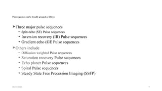
• Types of basic pulse sequence
• Spin echo
• Gradient eco
• Inversion recovery
• Others
8/22/2019
3.
By solomon RR1,BDU 3
Learning Objectives
On completing this session, you should able to:-
• Understand the basic principles of MRI sequence
• Identify commonly used MRI sequence
• Differentiate between T1-weighted and T2 weighted image based on tissue
contrast
• Explain the clinical use of different MRI sequence
• Recognize the appearance of normal and pathologic finding on various MRI
sequence
• Select appropriate sequence for specific clinical indications
8/22/2019
4.
06/15/2025 4
Introduction
• MRIpulse sequences are programmed combinations of radio frequency pulses
and magnetic field gradients used to create, manipulate, and encode signals in
MRI.
• These sequences determine the appearance of the resulting image, influencing
contrast, resolution, and overall quality.
• They are carefully designed to control the way protons in the body respond to the
magnetic field, allowing for different image contrasts and the visualization of
various anatomical structures.
5.
06/15/2025 5
Cont…
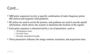
• MRIpulse sequences involve a specific combination of radio frequency pulses
(RF pulses) and magnetic field gradients.
• RF pulses are used to excite the protons, and gradients are used to encode spatial
information, which allows the scanner to determine the location of the signals.
• Each pulse sequence is characterized by a set of parameters, such as
• TR (Repetition Time)
• TE (Echo Time)
• flip angle, and gradient strength.
• These parameters influence the image contrast, resolution, and acquisition time.
6.
06/15/2025 6
Cont…
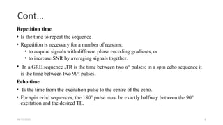
Repetition time
•Is the time to repeat the sequence
• Repetition is necessary for a number of reasons:
• to acquire signals with different phase encoding gradients, or
• to increase SNR by averaging signals together.
• In a GRE sequence ,TR is the time between two α° pulses; in a spin echo sequence it
is the time between two 90° pulses.
Echo time
• Is the time from the excitation pulse to the centre of the echo.
• For spin echo sequences, the 180° pulse must be exactly halfway between the 90°
excitation and the desired TE.
06/15/2025 8
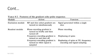
Cont…
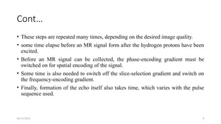
• Thesesteps are repeated many times, depending on the desired image quality.
• some time elapse before an MR signal form after the hydrogen protons have been
excited.
• Before an MR signal can be collected, the phase-encoding gradient must be
switched on for spatial encoding of the signal.
• Some time is also needed to switch off the slice-selection gradient and switch on
the frequency-encoding gradient.
• Finally, formation of the echo itself also takes time, which varies with the pulse
sequence used.
06/15/2025 10
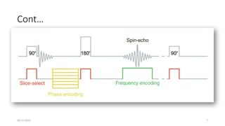
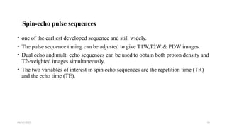
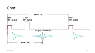
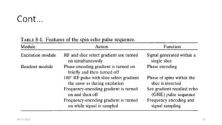
Spin-echo pulsesequences
• one of the earliest developed sequence and still widely.
• The pulse sequence timing can be adjusted to give T1W,T2W & PDW images.
• Dual echo and multi echo sequences can be used to obtain both proton density and
T2-weighted images simultaneously.
• The two variables of interest in spin echo sequences are the repetition time (TR)
and the echo time (TE).
11.
06/15/2025 11
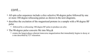
cont…
• Allspin echo sequences include a slice selective 90-degree pulse followed by one
or more 180 degree refocusing pulses as shown in the next diagrams.
• describes the excitation of the magnetized protons in a sample with a 90 degree RF
pulse
• followed by a refocusing 180-degree RF pulse to produce an echo.
• The 90-degree pulse converts Mz into Mxy,&
• creates the largest phase coherent transverse magnetization that immediately begins to decay at
a rate described by T2* relaxation.
12.
By solomon RR1,BDU 12
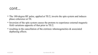
cont…
• The 180-degree RF pulse, applied at TE/2, inverts the spin system and induces
phase coherence at TE.
• Inversion of the spin system causes the protons to experience external magnetic
field variations opposite of that prior to TE/2.
• resulting in the cancellation of the extrinsic inhomogeneities & associated
dephasing effects.
8/22/2019
13.
06/15/2025 13
Cont…
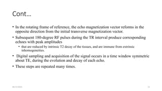
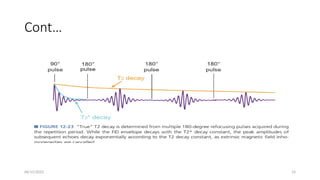
• Inthe rotating frame of reference, the echo magnetization vector reforms in the
opposite direction from the initial transverse magnetization vector.
• Subsequent 180-degree RF pulses during the TR interval produce corresponding
echoes with peak amplitudes
• that are reduced by intrinsic T2 decay of the tissues, and are immune from extrinsic
inhomogeneities.
• Digital sampling and acquisition of the signal occurs in a time window symmetric
about TE, during the evolution and decay of each echo.
• These steps are repeated many times.
06/15/2025 17
Spin EchoImage Contrast
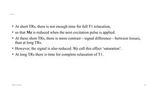
• At short TRs, there is not enough time for full T1 relaxation,
• so that Mz is reduced when the next excitation pulse is applied.
• At these short TRs, there is more contrast—signal difference—between tissues,
than at long TRs.
• However, the signal is also reduced. We call this effect ‘saturation’.
• At long TRs there is time for complete relaxation of T1.
18.
By solomon RR1,BDU 18
…
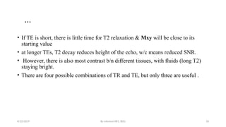
• If TE is short, there is little time for T2 relaxation & Mxy will be close to its
starting value
• at longer TEs, T2 decay reduces height of the echo, w/c means reduced SNR.
• However, there is also most contrast b/n different tissues, with fluids (long T2)
staying bright.
• There are four possible combinations of TR and TE, but only three are useful .
8/22/2019
19.
06/15/2025 19
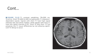
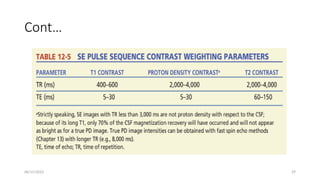
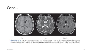
T1 Weighting
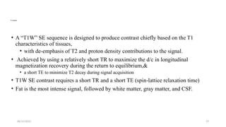
•A “T1W” SE sequence is designed to produce contrast chiefly based on the T1
characteristics of tissues,
• with de-emphasis of T2 and proton density contributions to the signal.
• Achieved by using a relatively short TR to maximize the d/c in longitudinal
magnetization recovery during the return to equilibrium,&
• a short TE to minimize T2 decay during signal acquisition
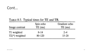
• T1W SE contrast requires a short TR and a short TE (spin-lattice relaxation time)
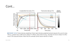
• Fat is the most intense signal, followed by white matter, gray matter, and CSF.
06/15/2025 22
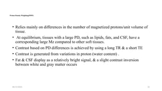
Proton DensityWeighting(PDW)
• Relies mainly on differences in the number of magnetized protons/unit volume of
tissue.
• At equilibrium, tissues with a large PD, such as lipids, fats, and CSF, have a
corresponding large Mz compared to other soft tissues.
• Contrast based on PD differences is achieved by using a long TR & a short TE
• Contrast is generated from variations in proton (water content) .
• Fat & CSF display as a relatively bright signal, & a slight contrast inversion
between white and gray matter occurs
06/15/2025 25
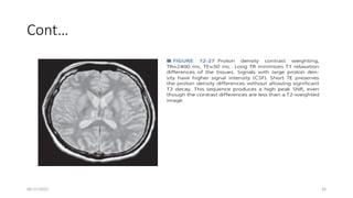
T2 Weighting(T2W)
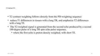
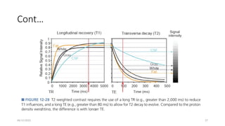
•T2 contrast weighting follows directly from the PD-weighting sequence
• reduce T1 differences in tissues with a long TR, and emphasize T2 differences
with a long TE.
• The T2-weighted signal is generated from the second echo produced by a second
180-degree pulse of a long TR spin echo pulse sequence,
• where the first echo is proton density weighted, with short TE.
26.
By solomon RR1,BDU 26
cont…
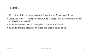
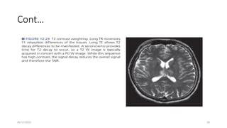
• T2 contrast differences are manifested by allowing M xy signal decay .
• Compared with a T1-weighted image, CSF is bright, and gray and white matter
are reversed in intensity.
• As TE is increased, more T2-weighted contrast is achieved.
• but at the expense of less M xy signal and greater image noise.
8/22/2019
06/15/2025 30
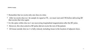
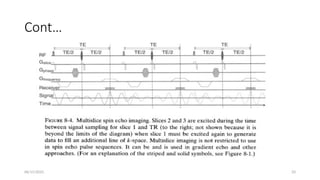
Multislice Imaging
•Remember that we excite only one slice at a time.
• After we excite slice no.1 & sample its signal at TE , we must wait until TR before delivering RF
that excites that slice again.
• b/c the spins within slice no.1 are recovering longitudinal magnetization after the RF pulse.
• However, this slice-selective RF pulse did not excite the rest of the patient.
• All tissue outside slice no.1 is fully relaxed, including tissue in the location of adjacent slices.
31.
06/15/2025 31
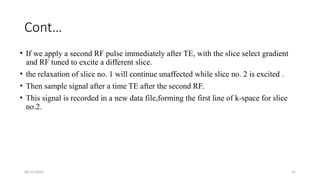
Cont…
• Ifwe apply a second RF pulse immediately after TE, with the slice select gradient
and RF tuned to excite a different slice.
• the relaxation of slice no. 1 will continue unaffected while slice no. 2 is excited .
• Then sample signal after a time TE after the second RF.
• This signal is recorded in a new data file,forming the first line of k-space for slice
no.2.
32.
By solomon RR1,BDU 32
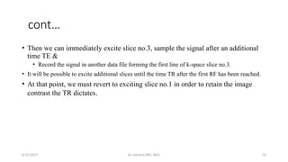
cont…
• Then we can immediately excite slice no.3, sample the signal after an additional
time TE &
• Record the signal in another data file forming the first line of k-space slice no.3.
• It will be possible to excite additional slices until the time TR after the first RF has been reached.
• At that point, we must revert to exciting slice no.1 in order to retain the image
contrast the TR dictates.
8/22/2019
06/15/2025 34
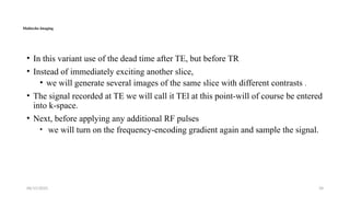
Multiecho Imaging
•In this variant use of the dead time after TE, but before TR
• Instead of immediately exciting another slice,
• we will generate several images of the same slice with different contrasts .
• The signal recorded at TE we will call it TEl at this point-will of course be entered
into k-space.
• Next, before applying any additional RF pulses
• we will turn on the frequency-encoding gradient again and sample the signal.
35.
By solomon RR1,BDU 35
cont…
• Notice that no additional phase encoding or slice selection is performed.
• The time at which we sample the signal this second time will be termed TE z, &
• it will be recorded in a new k-space.
• Each time repeat the RF pulse at TR, we will again record signal at TEl & TE z
• recording each in its respective k-space.
• Notice that within a given TR period, signal from each TE has identical spatial
localization (slice, phase, and frequency encoding),
8/22/2019
36.
06/15/2025 36
Cont…
• butit is recorded at a different time after the RF and in a separate k-space.
• Each k-space will yield a unique image:
• The contrast of the two images will differ in the degree to which they show contrast based on
T2.
• the multiecho technique is used with spin echo pulse sequences , a relatively long
TR & one short and one rather long TE (perhaps 20 &120ms).
• The result is two images: one with contrast mostly based on proton density (long
TR and short TE) and one based on T2 (long TR and TE).
37.
06/15/2025 37
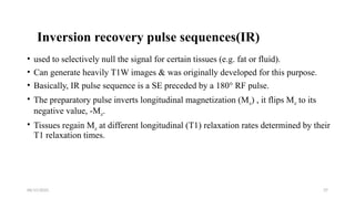
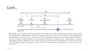
Inversion recoverypulse sequences(IR)
• used to selectively null the signal for certain tissues (e.g. fat or fluid).
• Can generate heavily T1W images & was originally developed for this purpose.
• Basically, IR pulse sequence is a SE preceded by a 180° RF pulse.
• The preparatory pulse inverts longitudinal magnetization (Mz) , it flips Mz to its
negative value, -Mz.
• Tissues regain Mz at different longitudinal (T1) relaxation rates determined by their
T1 relaxation times.
38.
06/15/2025 38
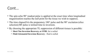
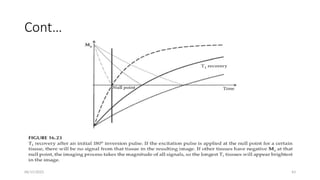
Cont…
• Thespin echo 90° readout pulse is applied at the exact time when longitudinal
magnetization reaches the null point for the tissue we wish to suppress.
• The time elapsed b/n the preparatory 180° pulse and the 90° excitation (slice
selection) RF pulse is termed time to inversion.
• By choosing the appropriate TI, suppression of different tissues is possible:
• Short Tau Inversion Recovery, or STIR: fat is nulled
• Fluid Attenuated Inversion Recovery - fluid is nulled
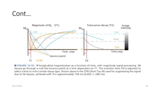
06/15/2025 40
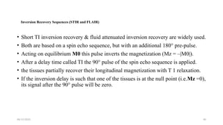
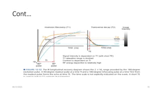
Inversion RecoverySequences (STIR and FLAIR)
• Short TI inversion recovery & fluid attenuated inversion recovery are widely used.
• Both are based on a spin echo sequence, but with an additional 180° pre-pulse.
• Acting on equilibrium M0 this pulse inverts the magnetization (Mz = –|M0|).
• After a delay time called TI the 90° pulse of the spin echo sequence is applied.
• the tissues partially recover their longitudinal magnetization with T 1 relaxation.
• If the inversion delay is such that one of the tissues is at the null point (i.e.Mz =0),
its signal after the 90° pulse will be zero.
41.
06/15/2025 41
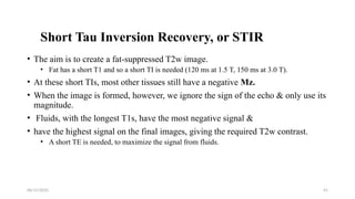
Short TauInversion Recovery, or STIR
• The aim is to create a fat-suppressed T2w image.
• Fat has a short T1 and so a short TI is needed (120 ms at 1.5 T, 150 ms at 3.0 T).
• At these short TIs, most other tissues still have a negative Mz.
• When the image is formed, however, we ignore the sign of the echo & only use its
magnitude.
• Fluids, with the longest T1s, have the most negative signal &
• have the highest signal on the final images, giving the required T2w contrast.
• A short TE is needed, to maximize the signal from fluids.
42.
06/15/2025 42
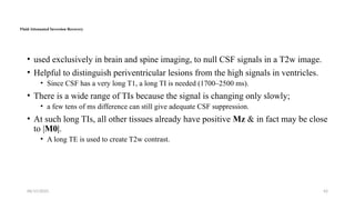
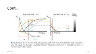
Fluid AttenuatedInversion Recovery
• used exclusively in brain and spine imaging, to null CSF signals in a T2w image.
• Helpful to distinguish periventricular lesions from the high signals in ventricles.
• Since CSF has a very long T1, a long TI is needed (1700–2500 ms).
• There is a wide range of TIs because the signal is changing only slowly;
• a few tens of ms difference can still give adequate CSF suppression.
• At such long TIs, all other tissues already have positive Mz & in fact may be close
to |M0|.
• A long TE is used to create T2w contrast.
06/15/2025 49
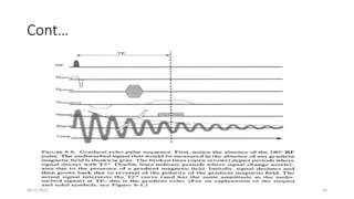
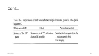
Gradient echosequences (GRE)
• Are an alternative technique to SE, differing from it in two principal points:
• Utilization of gradient fields to generate transverse magnetization
• Flip angles of less than 90°
• Compared to the SE, IR & gradient echo sequences are more versatile.
• Not only is the basic sequence varied by adding dephasing or rephasing gradients
at the end of the sequence
50.
06/15/2025 50
Cont…
• butthere is a significant extra variable to specify in addition to the usual TR &
TE.
• This variable is the flip or tip angle of the spins.
• The gradient echo is generated by the frequency-encode gradient, except that it is
used twice in succession, and in opposite directions:
• It is used in reverse at first to enforce transverse dephasing of spinning protons
and then right after.
51.
06/15/2025 51
Cont…
• Anotherimportant feature of GRE is that the dephasing of spinning protons
occurs as a result of T2* decay.
• which is more rapid than the T2 decay process underlying a spin-echo sequence (leading to
shorter TE) and is susceptible to static field inhomogeneitie.
• The ability to use a short TE is also important because signal decays much more
rapidly in GRE, with T2*.
• used as a readout gradient to re-align the dephased protons and acquire signal.
52.
By solomon RR1,BDU 52
cont…
• B/c low flip angles are used, there is some retention of the original longitudinal
magnetization as opposed to the 90° pulse used in spin echo,
• which completely eliminates the longitudinal magnetization.
• As a result, the build-up time for longitudinal magnetization is significantly
reduced for the subsequent pulses, allowing faster image acquisition in GE.
• A gradient echo is essentially a means for minimizing the signal loss incurred
during signal sampling under the frequency-encoding gradient.
8/22/2019
53.
06/15/2025 53
Cont…
• Toform a gradient echo, first turn on frequency-encoding gradient magnetic field.
• This leads to signal loss.
• After gradient is switched off, spins are out of phase &
• signal has been lost in proportion to the strength of the gradient magnetic field.
• If we now turn on the same gradient magnetic field with the same strength but
opposite polarity,
• the spins will undergo further "dephasing," but enough dephasing actually leads to rephasing
• This is a gradient echo.
06/15/2025 56
Flip angle
•Is usually at /close to 90 degrees for a spin echo but is less on GRE sequences
• commonly varying over a range of 10 to 80 degrees (usually denoted by α).
• For the basic GRE sequence FLASH, the larger flip angles give more T1W to the
image &
• the smaller flip angles give more T2, or actually T2* weighting, to the images.
• So a small flip angle can be used to avoid saturation, even when TR is very short.
• Flip angle becomes the parameter w/c controls M z, while TE still controls Mxy.
57.
06/15/2025 57
Cont…
• Combinationsof flip angle and TE, but only three are useful .
• Small α°, short TE:
• contrast is dominated by the proton density (water content) of the tissues
• Small α°, long TE:
• contrast depends on T2 (spin-spin relaxation time, or to be more correct T2* the effective spin-spin relaxation time)
• Large α°, short TE:
• contrast is dictated by T1 (spin-lattice relaxation time)
• The fourth combination, large α° with long TE, has no value.
06/15/2025 61
Coherent GradientEcho
• The timing of the RF pulse with the dephasing & rephasing implemented by reversal of
gradient polarity to generate an echo at a TE for the frequency encode gradient (FEG).
• Also involved phase encode gradient (PEG), which is applied & incrementally changed
for each TR
• for identify proton position in the direction perpendicular to the FEG based upon phase changes of
the protons after the PEG is turned off.
• The combined FID and simulated echo signals are generated during the GE, and produce
tissue contrast dependent on flip angle, TR, and TE.
• With moderate flip angles of 30 -60 degrees, the d/c in tissue contrast are primarily based upon
T2/T1 ratios.
62.
06/15/2025 62
Incoherent, “Spoiled”Gradient Echo
• With short TR steady-state acquisitions,T1W can,t be achieved to any great extent.
• owing to either a small d/c in longitudinal magnetization with small flip angles or
• dominance of the T2* effects for larger flip angles.
• T2* influence can be reduced by using a long TR or
• by “spoiling” the steady-state transverse magnetization by introducing incoherent phase
differences from pulse to pulse.
• The latter is achieved by adding a phase shift to successive RF pulses during the excitation
of protons.
• Both the RF transmitter and RF receiver are phase locked, so that the receiver discriminates
the phase of the GE from the SE generated by the previous RF pulse,
63.
06/15/2025 63
Others….
Diffusion-weighted imaging(DWI)
• is a form of MR imaging based upon measuring the random Brownian motion of
water molecules within a voxel of tissue.
• highly cellular tissues or those with cellular swelling exhibit lower diffusion
coefficients.
• Diffusion is particularly useful in tumor characterization and cerebral ischemia
64.
06/15/2025 64
Saturation recovery(SR) sequences
• Their primary use is to measure T1 times more quickly than an IR pulse sequence.
• consist of multiple 90 degree RF pulses at relatively short repetition times.
• Longitudinal magnetization develops during the TR period after the dephasing
gradient is rotated into the transverse plane by another 90 degree pulse.
• A gradient echo is acquired immediately after this.
• The signal will reflect T1 differences in tissues because of different amounts of
longitudinal recovery during the TR period.
65.
06/15/2025 65
Cont…
Echo planarimaging (EPI)
• is an MRI acquisition methodology with an excellent temporal resolution that is
required in specific clinical settings e.g. cardiac imaging.
• There are single-shot and multi-shot echo-planar sequences.
• Is performed using a pulse sequence in which multiple echoes of different phase
steps are acquired using re phasing gradients
• instead of repeated 180-degree RF pulses following the 90°/180° in a SE sequences.
66.
06/15/2025 66
Cont…
• Accomplishedby rapidly reversing the readout or frequency-encoding gradient.
• This switching or reversal may also be done in a sinusoidal fashion.
• Echo planar sequences may use entirely gradient echoes or may combine a spin-
echo with the train of gradient echoes.
• In a single-shot echo-planar sequence, the entire range of phase encoding steps,
• In multi-shot echo-planar imaging, the range of phase steps is equally divided into
several "shots" or TR periods.
• Each subsequent echo results in a progressively T2-weighted signal.
67.
06/15/2025 67
Cont…
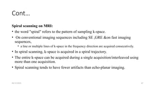
Spiral scanningon MRI:
• the word "spiral" refers to the pattern of sampling k-space.
• On conventional imaging sequences including SE ,GRE &on fast imaging
sequences,
• a line or multiple lines of k-space in the frequency direction are acquired consecutively.
• In spiral scanning, k-space is acquired in a spiral trajectory.
• The entire k-space can be acquired during a single acquisition/interleaved using
more than one acquisition.
• Spiral scanning tends to have fewer artifacts than echo-planar imaging.
68.
06/15/2025 68
Cont…
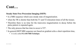
Steady StateFree Precession Imaging (SSFP):
• Is a MRI sequence which uses steady state of magnetization.
• when the TR is shorter than both the T1 and T2 relaxation times of all the tissues.
• Therefore there is no time for the transverse magnetization to decay before the
pulse pattern is repeated again.
• The only process that has time to occur is T2*.
• In general,SSFP MRI sequence are based on gradient echo a short repetition time,
• it is also called FLASH MRI Technique.
69.
06/15/2025 69
Reference
• Diagnosticradiology physics
• Totally accessible mri,a user's guide to principles, technology, and applications,
• Physics for diagnostic radiology,3rd
edition
• The essential physics of medical imaging
• The physics of diagnosting imaging 2nd
edition
• Radiopedia


![[DSC Europe 25] Tamas Srancsik - How To Teach Your AI Football? An Argument f...](https://cdn.slidesharecdn.com/ss_thumbnails/bcjh1m9xtbosv20ucftb-tamas-srancsik-how-to-teach-your-ai-football-260121115910-08b53e9e-thumbnail.jpg?width=640&height=640&fit=bounds)

![[DSC Europe 25] Srdj Stanisic - Local and Private AI in UX.pdf](https://cdn.slidesharecdn.com/ss_thumbnails/vwmetykqmztgmokmmkfa-3-srdjan-stanisic-local-and-small-ai-in-ux-260120105855-55a31869-thumbnail.jpg?width=640&height=640&fit=bounds)

![[DSC Europe 25] Bojan Djuricic - Predictive Design Process.pdf](https://cdn.slidesharecdn.com/ss_thumbnails/5awdrbedqdek3gqu2ezy-4-the-predictive-design-bojan-djuricic-260120105856-6c399e9b-thumbnail.jpg?width=640&height=640&fit=bounds)

![[DSC Europe 25] Tali Fulman - Guild Meetings, Then What? Building Data Commun...](https://cdn.slidesharecdn.com/ss_thumbnails/fgohhi33rwmhqdowdj5k-tali-fulman-guild-meetings-then-what-building-data-communities-that-actually-ch-260120105855-528492c3-thumbnail.jpg?width=640&height=640&fit=bounds)
![[DSC Europe 25] Mikhail Rozhkov - AI Product Canvas: From Business Goals to T...](https://cdn.slidesharecdn.com/ss_thumbnails/d53doddtpgfqivmzqel6-mikhail-rozhkov-ai-product-canvas-v1-260121115910-9dd517a7-thumbnail.jpg?width=640&height=640&fit=bounds)
![[DSC Europe 25] Andrzej Kowalczyk - AI - how to start small and grow in the f...](https://cdn.slidesharecdn.com/ss_thumbnails/oy1zmo94qv6vpcqjvno2-andrzej-kowalczyk-ai-how-to-start-small-and-grow-in-the-future-1-260119121559-cf093b23-thumbnail.jpg?width=640&height=640&fit=bounds)
![[DSC Europe 25] Harshvardhan Jain - From Pre-Trained to Purpose-Built: Fine-T...](https://cdn.slidesharecdn.com/ss_thumbnails/zru4zmiseku5tgvu2dgw-harshvardhan-jain-from-pre-trained-to-purpose-built-fine-tuning-llms-for-high-i-260119101520-8335585f-thumbnail.jpg?width=640&height=640&fit=bounds)


![[DSC Europe 25] Marcos Heidemann - Beyond the Hype: Making AI Coding Assistan...](https://cdn.slidesharecdn.com/ss_thumbnails/eexkhvldrjsopspdjbur-marcos-heidemann-beyond-the-hype-getting-real-value-out-of-ai-assisted-coding-260121115910-7e9d41ec-thumbnail.jpg?width=640&height=640&fit=bounds)

