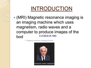
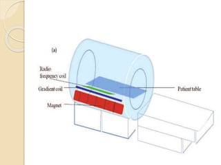
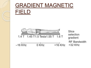
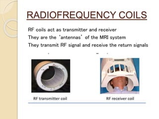
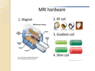
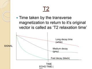
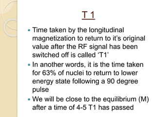
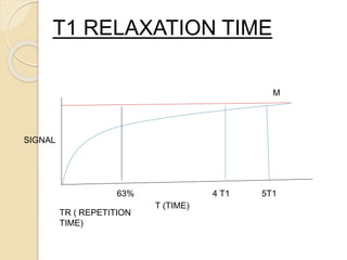
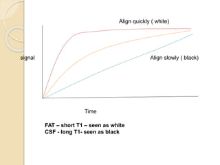
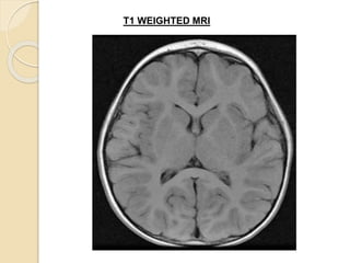
BASIC
PRINCIPLES
OF MRI
INTRODUCTION
 (MRI) Magnetic resonance imaging is
an imaging machine which uses
magnetism, radio waves and a
computer to produce images of the
body structures.
COMPONENTS OF MRI
1. Scanner
2. Computer
3. Recording hardware
MRI scanner is a large tube that contains
powerful magnet.
Main components of scanner are:
1. Static magnetic field coils
2. Gradient coils
3. RF ( radiofrequency coils)
STATIC MAGNETIC FIELD
(B)
3 methods to generate magnetic field
1) Fixed magnet
2) Resistive magnet
3) Super conducting magnet
 Fixed magnets and resistive magnets are generally
restricted to field strengths below 0.4 tesla
 High-resolution imaging systems use super
conducting magnets
 Super conducting magnets are large and complex
 They need the coils to be soaked in liquid helium to
reduce their temperature
GRADIENT COILS
 Gradient coils are used to produce deliberate
variations in the main magnetic field
 These variations allow for localization of the
tissue slicing as well as for phase encoding
and frequency encoding
GRADIENT MAGNETIC
FIELD
RADIOFREQUENCY COILS
RF coils act as transmitter and receiver
They are the ‘antennas’ of the MRI system
They transmit RF signal and receive the return signals
 Four basic steps are involved in
getting an MR image
1. Placing the patient in the magnet.
2. Sending Radiofrequency (RF)
pulse by coil
3. Receiving signals from the patient by
coil.
4. Transformation of signals into image
by complex processing in the
computers
BASIC PRINCIPLE OF MRI
 MRI is based on the principle of NMR
( nuclear magnetic resonance)
 NMR – certain atomic nuclei
demonstrate the ability to absorb and
re-emit RF energy when placed in a
magnetic field
 H atoms are most commonly used as
they are present everywhere in body
 SPIN ANGULAR MOMENTUM (h) : spin is an intrinsic
angular momentum of charged nucleus
 There are 2 types of spins called as ‘spin up’ and
‘spin down’
MAGNETIC DIPOLE MOMENT (nu) : It is defined as the
property of a nucleus that causes it to behave like a tiny
bar magnet i.e it tries to align itself parallel in a magnetic
field
GYROMAGNETIC RATIO:
It is a unique value for each type of nucleus given by
Gamma (y) gyromagnetic ratio = Magnetic dipole moment (nu)
spin angular momentum (h)
PRECESSION:
It is defined as the change in the rotational axis of a rotating body
when an external magnetic field ( torque) is applied.
Larmor frequency: defines that each type of nucleus will precess at a
unique frequency in the magnetic field
(w) omega = (y) gyromagnetic ratio * (B) magnetic field
1. Precession frequency is never constant
2. It is proportional to B, i.e the external magnetic field
3. It becomes higher as the strength of the external magnetic field
increases
 CONCEPT OF MAGNETIZATION (M) :
MAGNETIZATION (M): is defined as the net single
vector obtained by adding all the individual MDMs
 THE COORDINATE SYSTEM:
 Z
Y
X
B 1. Without any external magnetic
field ( torque) applied, the net
magnetization (M) is oriented
towards B
2. B being a very strong magnet,
with field strength 5000-10,000
times the magnetic field of earth
3. This portion of M aligned in
direction of B i.e Z represents
the ‘LONGITUDINAL
MAGNETIZATION’ which is not
much useful in determining the
precessing frequency
Note : X,Y, Z represent the
vectors of magnetization M
z
y
B
B1
Transverse plane : it is the plane perpendicular to B ( x,
y vectors)
TRANSVERSE MAGNETIZATION: When a magnetic
field perpendicular to B is applied i.e B1, the
magnetization is flipped out of alignment with B and this
angle is called ‘flip angle’
Transverse magnetization needs to take place for the
protons to precess and this is achieved by giving the
radiofrequency signal ( RF signal )
If the applied B1 is long enough to flip the M by 90
degree we called it a ‘90 degree pulse’
M
INTRODUCTION TO RELAXATION:
FREE INDUCTION DECAY:
Precession of the particles is influenced by the radio frequency pulse given
PERFECT COHERENCE OF SPINS WHEN THE RF SIGNAL IS
ON
Once the coherence of all the particles goes out of phase after
switching off the
RF signal, they are said to be defaced ( decaying of signal)
This is called as the free induction decay.
TRANSVERSE RELAXATION
 When the Rf pulse is switched off, the
protons precessing lose their phase
(dephasing) and their precessing
decreases
 This is calles as ‘transverse relaxation’
LONGITUDINAL RELAXATION
 When the radiofrequency (RF) pulse is
switched off, the high energy protons
tend to transfer energy to surrounding
lattice and align themselves along z-
axis
 This is called as longitudinal relaxation
B
x
Y
z
M
T2
 Time taken by the transverse
magnetization to return to it’s original
vector is called as ‘T2 relaxation time’
SIGNAL
TIME
Long decay time
(white)
Medium decay
(grey)
Fast decay (black)
ECHO TIME (
T2 WEIGHTED MRI
SPIN-SPIN RELAXATION
TIME
 As the protons lose their precession
and begin to relax, they transfer their
energy to low energy protons in the
process of defacement.
 Hence T2 is also called as spin-spin
relaxation time.
 Differences in T2 among various
tissues occurs due to the
inhomogenicity among the tissues
 E.g CSF has uniform diffusion and the
spin energy is not transferred easily
hence it has long T2 ( long decay
time)
 Bone has compact structural integrity
with a tightly packed spins and hence
the spin energy is transferred easily
to lower spins resulting in short T2
(short decay time)
T 1
 Time taken by the longitudinal
magnetization to return to it’s original
value after the RF signal has been
switched off is called ‘T1’
 In another words, it is the time taken
for 63% of nuclei to return to lower
energy state following a 90 degree
pulse
 We will be close to the equilibrium (M)
after a time of 4-5 T1 has passed
M
T (TIME)
SIGNAL
T1 RELAXATION TIME
63% 4 T1 5T1
TR ( REPETITION
TIME)
Time
signal
Align quickly ( white)
Align slowly ( black)
FAT – short T1 – seen as white
CSF - long T1- seen as black
T1 WEIGHTED MRI
 SPIN-LATTICE RELAXATION :
 During the process of re-alignment
along the magnetic field, the protons
transfer their energy to the
surrounding lattice and therefore T1 is
also called as spin- lattice relaxation
time
 MEASURING T1: the return of nuclei
to equilibrium state does not give an
NMR signal
 T1 cant be measured by NMR
technique
 If surrounding structures have
magnetic field which fluctuate around
larmor frequency, the transfer of
energy is easy and the relaxation is
faster
 E.g fatty acids have frequency similar
to larmor frequency and have short T1
 Water has diffuse movement and has
longer T1
 This is done by keeping the TR short.
If TR is long the tissues with long T1
will also regain maximum LM giving
stronger signal with next RF pulse.
 This will result in no significant
difference between signal intensity of
tissues with different T1. With short TR
only the tissues with short T1 will
show high signal intensity.
TI WEIGHTED
IMAGES:
T2 WEIGHTED IMAGES
 The images are made T2-wighted by
keeping the TE longer. At short TE,
tissues with long as well as short T2
have strong signal. Therefore,
 . At longer TE, only those tissues with
long T2 will have sufficiently strong
signal and the signal difference
between tissues with short and long
T2 will be pronounced .
THANK YOU

Basic principles of mri

  • 1.
  • 2.
    INTRODUCTION  (MRI) Magneticresonance imaging is an imaging machine which uses magnetism, radio waves and a computer to produce images of the body structures.
  • 3.
    COMPONENTS OF MRI 1.Scanner 2. Computer 3. Recording hardware MRI scanner is a large tube that contains powerful magnet. Main components of scanner are: 1. Static magnetic field coils 2. Gradient coils 3. RF ( radiofrequency coils)
  • 4.
    STATIC MAGNETIC FIELD (B) 3methods to generate magnetic field 1) Fixed magnet 2) Resistive magnet 3) Super conducting magnet  Fixed magnets and resistive magnets are generally restricted to field strengths below 0.4 tesla  High-resolution imaging systems use super conducting magnets  Super conducting magnets are large and complex  They need the coils to be soaked in liquid helium to reduce their temperature
  • 6.
    GRADIENT COILS  Gradientcoils are used to produce deliberate variations in the main magnetic field  These variations allow for localization of the tissue slicing as well as for phase encoding and frequency encoding
  • 7.
  • 8.
    RADIOFREQUENCY COILS RF coilsact as transmitter and receiver They are the ‘antennas’ of the MRI system They transmit RF signal and receive the return signals
  • 10.
     Four basicsteps are involved in getting an MR image 1. Placing the patient in the magnet. 2. Sending Radiofrequency (RF) pulse by coil 3. Receiving signals from the patient by coil. 4. Transformation of signals into image by complex processing in the computers
  • 11.
    BASIC PRINCIPLE OFMRI  MRI is based on the principle of NMR ( nuclear magnetic resonance)  NMR – certain atomic nuclei demonstrate the ability to absorb and re-emit RF energy when placed in a magnetic field  H atoms are most commonly used as they are present everywhere in body
  • 12.
     SPIN ANGULARMOMENTUM (h) : spin is an intrinsic angular momentum of charged nucleus  There are 2 types of spins called as ‘spin up’ and ‘spin down’
  • 13.
    MAGNETIC DIPOLE MOMENT(nu) : It is defined as the property of a nucleus that causes it to behave like a tiny bar magnet i.e it tries to align itself parallel in a magnetic field
  • 14.
    GYROMAGNETIC RATIO: It isa unique value for each type of nucleus given by Gamma (y) gyromagnetic ratio = Magnetic dipole moment (nu) spin angular momentum (h) PRECESSION: It is defined as the change in the rotational axis of a rotating body when an external magnetic field ( torque) is applied. Larmor frequency: defines that each type of nucleus will precess at a unique frequency in the magnetic field (w) omega = (y) gyromagnetic ratio * (B) magnetic field 1. Precession frequency is never constant 2. It is proportional to B, i.e the external magnetic field 3. It becomes higher as the strength of the external magnetic field increases
  • 16.
     CONCEPT OFMAGNETIZATION (M) : MAGNETIZATION (M): is defined as the net single vector obtained by adding all the individual MDMs  THE COORDINATE SYSTEM:  Z Y X B 1. Without any external magnetic field ( torque) applied, the net magnetization (M) is oriented towards B 2. B being a very strong magnet, with field strength 5000-10,000 times the magnetic field of earth 3. This portion of M aligned in direction of B i.e Z represents the ‘LONGITUDINAL MAGNETIZATION’ which is not much useful in determining the precessing frequency Note : X,Y, Z represent the vectors of magnetization M
  • 17.
    z y B B1 Transverse plane :it is the plane perpendicular to B ( x, y vectors) TRANSVERSE MAGNETIZATION: When a magnetic field perpendicular to B is applied i.e B1, the magnetization is flipped out of alignment with B and this angle is called ‘flip angle’ Transverse magnetization needs to take place for the protons to precess and this is achieved by giving the radiofrequency signal ( RF signal ) If the applied B1 is long enough to flip the M by 90 degree we called it a ‘90 degree pulse’ M
  • 18.
    INTRODUCTION TO RELAXATION: FREEINDUCTION DECAY: Precession of the particles is influenced by the radio frequency pulse given PERFECT COHERENCE OF SPINS WHEN THE RF SIGNAL IS ON
  • 19.
    Once the coherenceof all the particles goes out of phase after switching off the RF signal, they are said to be defaced ( decaying of signal) This is called as the free induction decay.
  • 20.
    TRANSVERSE RELAXATION  Whenthe Rf pulse is switched off, the protons precessing lose their phase (dephasing) and their precessing decreases  This is calles as ‘transverse relaxation’
  • 21.
    LONGITUDINAL RELAXATION  Whenthe radiofrequency (RF) pulse is switched off, the high energy protons tend to transfer energy to surrounding lattice and align themselves along z- axis  This is called as longitudinal relaxation B x Y z M
  • 22.
    T2  Time takenby the transverse magnetization to return to it’s original vector is called as ‘T2 relaxation time’ SIGNAL TIME Long decay time (white) Medium decay (grey) Fast decay (black) ECHO TIME (
  • 23.
  • 24.
    SPIN-SPIN RELAXATION TIME  Asthe protons lose their precession and begin to relax, they transfer their energy to low energy protons in the process of defacement.  Hence T2 is also called as spin-spin relaxation time.
  • 25.
     Differences inT2 among various tissues occurs due to the inhomogenicity among the tissues  E.g CSF has uniform diffusion and the spin energy is not transferred easily hence it has long T2 ( long decay time)  Bone has compact structural integrity with a tightly packed spins and hence the spin energy is transferred easily to lower spins resulting in short T2 (short decay time)
  • 26.
    T 1  Timetaken by the longitudinal magnetization to return to it’s original value after the RF signal has been switched off is called ‘T1’  In another words, it is the time taken for 63% of nuclei to return to lower energy state following a 90 degree pulse  We will be close to the equilibrium (M) after a time of 4-5 T1 has passed
  • 27.
    M T (TIME) SIGNAL T1 RELAXATIONTIME 63% 4 T1 5T1 TR ( REPETITION TIME)
  • 28.
    Time signal Align quickly (white) Align slowly ( black) FAT – short T1 – seen as white CSF - long T1- seen as black
  • 29.
  • 30.
     SPIN-LATTICE RELAXATION:  During the process of re-alignment along the magnetic field, the protons transfer their energy to the surrounding lattice and therefore T1 is also called as spin- lattice relaxation time  MEASURING T1: the return of nuclei to equilibrium state does not give an NMR signal  T1 cant be measured by NMR technique
  • 31.
     If surroundingstructures have magnetic field which fluctuate around larmor frequency, the transfer of energy is easy and the relaxation is faster  E.g fatty acids have frequency similar to larmor frequency and have short T1  Water has diffuse movement and has longer T1
  • 33.
     This isdone by keeping the TR short. If TR is long the tissues with long T1 will also regain maximum LM giving stronger signal with next RF pulse.  This will result in no significant difference between signal intensity of tissues with different T1. With short TR only the tissues with short T1 will show high signal intensity. TI WEIGHTED IMAGES:
  • 34.
  • 35.
     The imagesare made T2-wighted by keeping the TE longer. At short TE, tissues with long as well as short T2 have strong signal. Therefore,  . At longer TE, only those tissues with long T2 will have sufficiently strong signal and the signal difference between tissues with short and long T2 will be pronounced .
  • 36.