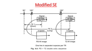
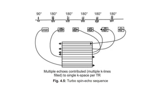
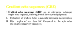
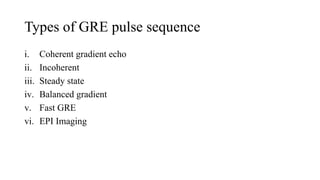
MRI PULSE SEQUENCE
VANI PUSHPA B.Sc, M.Sc in Medical Imaging Technology
ASSISTANT PROFESSOR
INCHARGE OF RADIODIAGNOSIS
FATHIMA INSTITUE OF MEDICAL SCIENCES
vanipushpa999@gmail.com
Topic to be cover
• Introduction
• Revision of basic concepts
• Pulse sequences
• Spin echo sequences
• Types
• Parameters
• Conclusion
• Summary
Introduction
• The MRI pulse sequences are the series of radiofrequency pulses
applied to the tissues to generate the images.
• The way in which the RF coil and gradient fields are turned on and off
is call pulse sequence.
• The R/f pulse is applied for the excitation purposes and in the case of
spin echo(SE) sequence also for rephasing purpose.
• Therefore pulse sequence is a co-ordinated and timed sequence of
events to generates a particular type of image contrast.
What is RF Pulse?
• RF pulse is define as the form of pocket of energy which is use in MRI
to produce the image of objects.
• There are two type of RF pulse used in MRI, first is called 90 degree
or excitation pulse, excited the NMV(protons) from longitudinal to
transverse plane.
• Another one is 180 degree Re-Phasing/refocusing pulse to recover the
excited protons from transverse magnetization to longitudinal
magnetization.
Pulse timing parameters :
• Each MRI pulse sequences consist of a number of parameters and
multiple sequences are grouped together into a MRI protocol.
• These parameters include: Time of echo (TE), Time of repetition
(TR), Flip angle.
i. Time of echo (TE):- It is the time interval between start of R/F
pulse and reception of the echo or signal.
ii. Time of repetition (TR):- It is the time interval between start of
one R/F pulse and start of next R/F pulse.
Flip angle:-It is the angle by which longitudinal magnetization
vector is rotated away from z-axis by R/F pulse. Shorter the flip
angle less will be scanning time.
A basic pulse sequence
• Short TR and short TE gives T1-weighted images.
• Long TR and long TE gives T2-weighted images.
• Long TR and short TE gives proton density images.
T1 weighted image
• T1 weighted image also known as spin lattice image, is one of the
basic pulse sequences in MRI and demonstrate difference in the T1
relaxation time of tissues.
• A T1WI relies upon the longitudinal relaxation of a tissues net
magnetization vector.
• Basically spins aligned in an external magnetic field (B0) are put into
transverse plane by the RF pulse.
• They then slide back towards the original equilibrium of B0.
• Not all tissues return back to equilibrium in the same amount of time.
• T1 weighted image having short TE & TR times.
• Fat quickly realign its longitudinal magnetization with Bo and
therefore it appears bright on T1 image.
• Water has much slower longitudinal magnetization realignment
after RF pulse and therefore have less transverse magnetization
after an RF pulse .
• Thus water have low signal and appears dark.
T2 weighted image
• A T2 weighted image relies upon the transverse relaxation of the net
magnetization vector.
• T2 weighted image required long TE & TR.
• After an excitation pulse, there is relaxation of the spin from the
transverse plane towards the main magnetic field and this is T1
weighted.
• At the same time spin are decaying from aligned precession in the
transverse plane and differences of this decay are consider as T2
weighted image.
MR Image appearance
• The easiest way to identify the T1WI and T2WI is to look the fluid
filled space in the body like CSF fluid in brain ventricles, synovial
fluids, free fluid in abdomen etc.
• Fluids appear dark on the T1 weighted image while appears bright on
T2 weighted image.
Proton density weighted image(PD)
• Proton density is the number of excitable spin per unit volume.
• It determines the maximum signals that can be obtained from a
given tissue.
• The image contrast on PD sequence is not depend upon the T1 or
T2 Relaxation .
• Signals are completely depends upon the amount of protons in the
tissue.
• Less protons means low signal and appear dark area on the image
while more protons produce a lot of signal and leads to bright on
the image.
• PD image is acquired with long TR and short TE.
• PD sequences are very useful to evaluating the structure with low
signal intensities like bones, connective tissue( ligaments and
tendons).
• Its often used for high resolution image .
• The application of these sequence including brain, spine and
MSK .
Free induction decay(FID)
• After switch off the RF pulse the amount of magnetization in
longitudinal plane gradually increase , called recovery.
• At the same time amount of magnetization gradually decreases in
transverse plane and it known as decay.
• During the period of switching off 90 degree pulse and receiving 180
degree pulse some amount of magnetization signal also loss and this is
called FID.
• And this signal is received in the form of T2⁎ decay or T2⁎ imaging.
• T2⁎ decay is faster than T2 decay.
. Pulse sequences are generally classified as:
I. Spin echo pulse sequence:- Spins are rephased by a 180 degree
rephasing pulse.
II. Gradient echo pulse sequence: Spins are rephased by a gradient.
Spin-echo pulse sequences
• Spin-echo pulse sequences are one of the earliest developed pulse
sequence and still used in MRI.
• All spin echo sequences include an excitation 90-degree pulse
followed by one or more 180 degree refocusing pulses .
• Excitation 90 degree pulse flip NMV from longitudinal axis to
transverse axis(x-y plane).
• After the switching of protons start dephasing.
• Immediately 180 degree rephasing pulse sent.
Types of SE
Conventional SE
Turbo / Fast SE
Inversion Recovery.
Conventional SE
• Conventional spin echo use one 90 degree excitation pulse followed
by one or more 180 degree pulse to generate a spin echo.
• It is gold standard for most of the MR imaging.
• They used for almost every MR examination.
• It is very useful to generate the T1 weighted image.
Modified SE
Fast/Turbo spin echo
• Its also a type of spin echo pulse sequence, having much shorter scan
time than conventional spin echo.
• In fast spin echo, the scan time reduced by performing more than one
phase encoding step and filling more than one K-space at a single
time.
• This is achieved by using multiple 180 degree re-phasing pulse
sequence to produce a train of echo.
• In this sequence multiple echoes obtained per TR
Turbo factor
• Turbo factor is define as the number of 180 degree pulse after
90 degree pulse.
• Its also known as a echo train length.
Inversion recovery pulse sequence
• It consists of an inverting 180 degree pulse followed by 90 degree
excitation pulse followed by re-phasing 180 degree pulse.
• 180 degree pulse saturate the NMV to the opposite side of z-axis(z
negative).
• After 180 degree IR pulse switched of NMV begins to relax back or
gradually builds back along positive side of z-axis.
• After a time 90 degree excitation pulse is applied .
• This time between 180 degree inverting pulse and 90 degree
excitation pulse is called time to invert(TI).
• TI is the main determinant of contrast in IR sequence.
• The 90 degree pulse flip NMV go transverse plane when it is
switched off it start to de-phasing and magnitude of TM reduce,
180 degree re-phasing pulse applied to get the signal just like spin
echo sequence.
• Re-phasing can also be done by gradient instead of 180 degree
pulse.
• However, image in IR sequence is heavily T1 weighted image
because of 180 degree pulse fully saturates the signal achieve large
contrast difference between fat and water.
• It is very useful to suppress a particular tissue signal.
IR
Types of IR
• STIR( short tow inversion recovery) : use shorter TI 80- 150 ms .
• It is very useful to suppress the signal of fat .
• FLAIR( fluid level attenuation inversion recovery ) : It use longer TI
time range between 1500 -2500 ms)..
• It used to suppress the fluid signal.
STIR
1. Short TI of 80-150 ms used.
2. Combined T1 and T2 weighting is
obtained
3. Fat, white matter can be
suppressed
4. Mainly used in body imaging
5. Cannot be used in post-contrast
imaging as short T1 tissue are
suppressed and contrast shortens
T1 of tissues taking up contrast.
FLAIR
1. Long TI of 1500-2500 ms is
used.
2. Heavily T2-weighted images
are obtained.
3. CSF, water is suppressed
4. Used in neuroimaging
5. Can be used in post-contrast
imaging.
FLAIR
STIR
Gradient echo sequences (GRE)
• Gradient echo sequences (GRE) are an alternative technique
to spin echo sequence, differing from it in two principal points:
I. Utilization of gradient fields to generate transverse magnetisation
II. Flip angles of less than 90° Compared to the spin echo
and inversion recovery sequences.
Types of GRE pulse sequence
i. Coherent gradient echo
ii. Incoherent
iii. Steady state
iv. Balanced gradient
v. Fast GRE
vi. EPI Imaging
EPI Imaging
• Echo planner imaging technique was developed by Sir Peter
Mansfield in 1977..
• Scanning time can be reduced by filling of multiple k-space in a
single TR.
• EPI follow this technique and all the line of k-space are filled with
single TR in EPI.
• These multiple echo may be generated by 180 degree re-phasing
pulse or with the help of gradient .
• Therefore EPI pulse sequence may be SE-EPI or GRE-EPI.
• SE-EPI having long scanning time so its not use routinely .
• GRE-EPI is very sensitive to susceptibility arteffect because T2*
decay is not compensated in GRE sequence.
• Application of EPI:
i. Diffusion imaging
ii. Perfusion imaging
iii. Functional imaging
iv. Cardiac imaging
v. Abdominal imaging

PULSE SCQUENCE-1.pptx

  • 1.
    MRI PULSE SEQUENCE VANIPUSHPA B.Sc, M.Sc in Medical Imaging Technology ASSISTANT PROFESSOR INCHARGE OF RADIODIAGNOSIS FATHIMA INSTITUE OF MEDICAL SCIENCES vanipushpa999@gmail.com
  • 2.
    Topic to becover • Introduction • Revision of basic concepts • Pulse sequences • Spin echo sequences • Types • Parameters • Conclusion • Summary
  • 3.
    Introduction • The MRIpulse sequences are the series of radiofrequency pulses applied to the tissues to generate the images. • The way in which the RF coil and gradient fields are turned on and off is call pulse sequence. • The R/f pulse is applied for the excitation purposes and in the case of spin echo(SE) sequence also for rephasing purpose. • Therefore pulse sequence is a co-ordinated and timed sequence of events to generates a particular type of image contrast.
  • 4.
    What is RFPulse? • RF pulse is define as the form of pocket of energy which is use in MRI to produce the image of objects. • There are two type of RF pulse used in MRI, first is called 90 degree or excitation pulse, excited the NMV(protons) from longitudinal to transverse plane. • Another one is 180 degree Re-Phasing/refocusing pulse to recover the excited protons from transverse magnetization to longitudinal magnetization.
  • 5.
    Pulse timing parameters: • Each MRI pulse sequences consist of a number of parameters and multiple sequences are grouped together into a MRI protocol. • These parameters include: Time of echo (TE), Time of repetition (TR), Flip angle. i. Time of echo (TE):- It is the time interval between start of R/F pulse and reception of the echo or signal. ii. Time of repetition (TR):- It is the time interval between start of one R/F pulse and start of next R/F pulse. Flip angle:-It is the angle by which longitudinal magnetization vector is rotated away from z-axis by R/F pulse. Shorter the flip angle less will be scanning time.
  • 6.
    A basic pulsesequence
  • 7.
    • Short TRand short TE gives T1-weighted images. • Long TR and long TE gives T2-weighted images. • Long TR and short TE gives proton density images.
  • 8.
    T1 weighted image •T1 weighted image also known as spin lattice image, is one of the basic pulse sequences in MRI and demonstrate difference in the T1 relaxation time of tissues. • A T1WI relies upon the longitudinal relaxation of a tissues net magnetization vector. • Basically spins aligned in an external magnetic field (B0) are put into transverse plane by the RF pulse. • They then slide back towards the original equilibrium of B0. • Not all tissues return back to equilibrium in the same amount of time.
  • 9.
    • T1 weightedimage having short TE & TR times. • Fat quickly realign its longitudinal magnetization with Bo and therefore it appears bright on T1 image. • Water has much slower longitudinal magnetization realignment after RF pulse and therefore have less transverse magnetization after an RF pulse . • Thus water have low signal and appears dark.
  • 10.
    T2 weighted image •A T2 weighted image relies upon the transverse relaxation of the net magnetization vector. • T2 weighted image required long TE & TR. • After an excitation pulse, there is relaxation of the spin from the transverse plane towards the main magnetic field and this is T1 weighted. • At the same time spin are decaying from aligned precession in the transverse plane and differences of this decay are consider as T2 weighted image.
  • 11.
    MR Image appearance •The easiest way to identify the T1WI and T2WI is to look the fluid filled space in the body like CSF fluid in brain ventricles, synovial fluids, free fluid in abdomen etc. • Fluids appear dark on the T1 weighted image while appears bright on T2 weighted image.
  • 13.
    Proton density weightedimage(PD) • Proton density is the number of excitable spin per unit volume. • It determines the maximum signals that can be obtained from a given tissue. • The image contrast on PD sequence is not depend upon the T1 or T2 Relaxation . • Signals are completely depends upon the amount of protons in the tissue. • Less protons means low signal and appear dark area on the image while more protons produce a lot of signal and leads to bright on the image.
  • 14.
    • PD imageis acquired with long TR and short TE. • PD sequences are very useful to evaluating the structure with low signal intensities like bones, connective tissue( ligaments and tendons). • Its often used for high resolution image . • The application of these sequence including brain, spine and MSK .
  • 15.
    Free induction decay(FID) •After switch off the RF pulse the amount of magnetization in longitudinal plane gradually increase , called recovery. • At the same time amount of magnetization gradually decreases in transverse plane and it known as decay. • During the period of switching off 90 degree pulse and receiving 180 degree pulse some amount of magnetization signal also loss and this is called FID. • And this signal is received in the form of T2⁎ decay or T2⁎ imaging. • T2⁎ decay is faster than T2 decay.
  • 16.
    . Pulse sequencesare generally classified as: I. Spin echo pulse sequence:- Spins are rephased by a 180 degree rephasing pulse. II. Gradient echo pulse sequence: Spins are rephased by a gradient.
  • 17.
    Spin-echo pulse sequences •Spin-echo pulse sequences are one of the earliest developed pulse sequence and still used in MRI. • All spin echo sequences include an excitation 90-degree pulse followed by one or more 180 degree refocusing pulses .
  • 18.
    • Excitation 90degree pulse flip NMV from longitudinal axis to transverse axis(x-y plane). • After the switching of protons start dephasing. • Immediately 180 degree rephasing pulse sent.
  • 20.
    Types of SE ConventionalSE Turbo / Fast SE Inversion Recovery.
  • 21.
    Conventional SE • Conventionalspin echo use one 90 degree excitation pulse followed by one or more 180 degree pulse to generate a spin echo. • It is gold standard for most of the MR imaging. • They used for almost every MR examination. • It is very useful to generate the T1 weighted image.
  • 22.
  • 23.
    Fast/Turbo spin echo •Its also a type of spin echo pulse sequence, having much shorter scan time than conventional spin echo. • In fast spin echo, the scan time reduced by performing more than one phase encoding step and filling more than one K-space at a single time. • This is achieved by using multiple 180 degree re-phasing pulse sequence to produce a train of echo. • In this sequence multiple echoes obtained per TR
  • 24.
    Turbo factor • Turbofactor is define as the number of 180 degree pulse after 90 degree pulse. • Its also known as a echo train length.
  • 26.
    Inversion recovery pulsesequence • It consists of an inverting 180 degree pulse followed by 90 degree excitation pulse followed by re-phasing 180 degree pulse. • 180 degree pulse saturate the NMV to the opposite side of z-axis(z negative). • After 180 degree IR pulse switched of NMV begins to relax back or gradually builds back along positive side of z-axis. • After a time 90 degree excitation pulse is applied . • This time between 180 degree inverting pulse and 90 degree excitation pulse is called time to invert(TI).
  • 27.
    • TI isthe main determinant of contrast in IR sequence. • The 90 degree pulse flip NMV go transverse plane when it is switched off it start to de-phasing and magnitude of TM reduce, 180 degree re-phasing pulse applied to get the signal just like spin echo sequence. • Re-phasing can also be done by gradient instead of 180 degree pulse. • However, image in IR sequence is heavily T1 weighted image because of 180 degree pulse fully saturates the signal achieve large contrast difference between fat and water. • It is very useful to suppress a particular tissue signal.
  • 28.
  • 29.
    Types of IR •STIR( short tow inversion recovery) : use shorter TI 80- 150 ms . • It is very useful to suppress the signal of fat . • FLAIR( fluid level attenuation inversion recovery ) : It use longer TI time range between 1500 -2500 ms).. • It used to suppress the fluid signal.
  • 30.
    STIR 1. Short TIof 80-150 ms used. 2. Combined T1 and T2 weighting is obtained 3. Fat, white matter can be suppressed 4. Mainly used in body imaging 5. Cannot be used in post-contrast imaging as short T1 tissue are suppressed and contrast shortens T1 of tissues taking up contrast. FLAIR 1. Long TI of 1500-2500 ms is used. 2. Heavily T2-weighted images are obtained. 3. CSF, water is suppressed 4. Used in neuroimaging 5. Can be used in post-contrast imaging.
  • 31.
  • 32.
    Gradient echo sequences(GRE) • Gradient echo sequences (GRE) are an alternative technique to spin echo sequence, differing from it in two principal points: I. Utilization of gradient fields to generate transverse magnetisation II. Flip angles of less than 90° Compared to the spin echo and inversion recovery sequences.
  • 33.
    Types of GREpulse sequence i. Coherent gradient echo ii. Incoherent iii. Steady state iv. Balanced gradient v. Fast GRE vi. EPI Imaging
  • 34.
    EPI Imaging • Echoplanner imaging technique was developed by Sir Peter Mansfield in 1977.. • Scanning time can be reduced by filling of multiple k-space in a single TR. • EPI follow this technique and all the line of k-space are filled with single TR in EPI. • These multiple echo may be generated by 180 degree re-phasing pulse or with the help of gradient . • Therefore EPI pulse sequence may be SE-EPI or GRE-EPI. • SE-EPI having long scanning time so its not use routinely . • GRE-EPI is very sensitive to susceptibility arteffect because T2* decay is not compensated in GRE sequence.
  • 35.
    • Application ofEPI: i. Diffusion imaging ii. Perfusion imaging iii. Functional imaging iv. Cardiac imaging v. Abdominal imaging