Download as PDF, PPTX

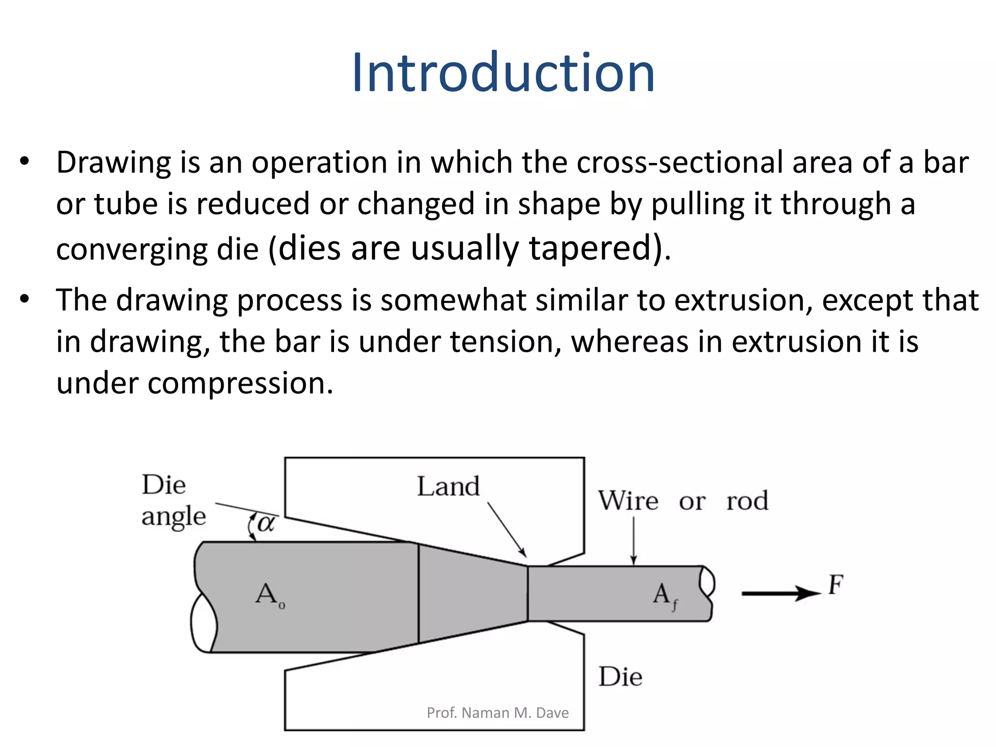
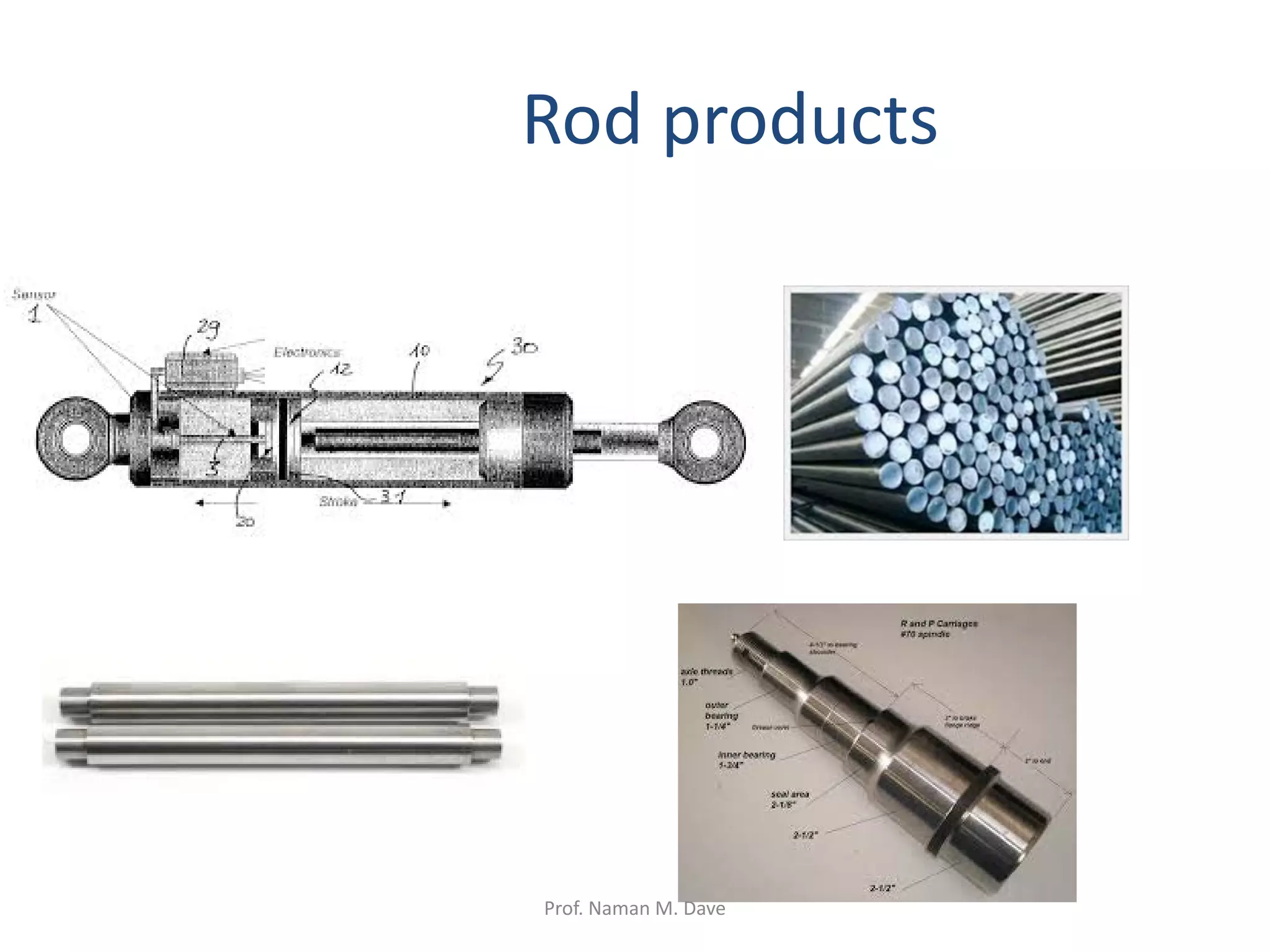
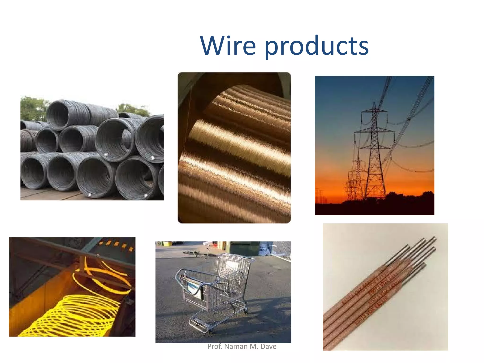
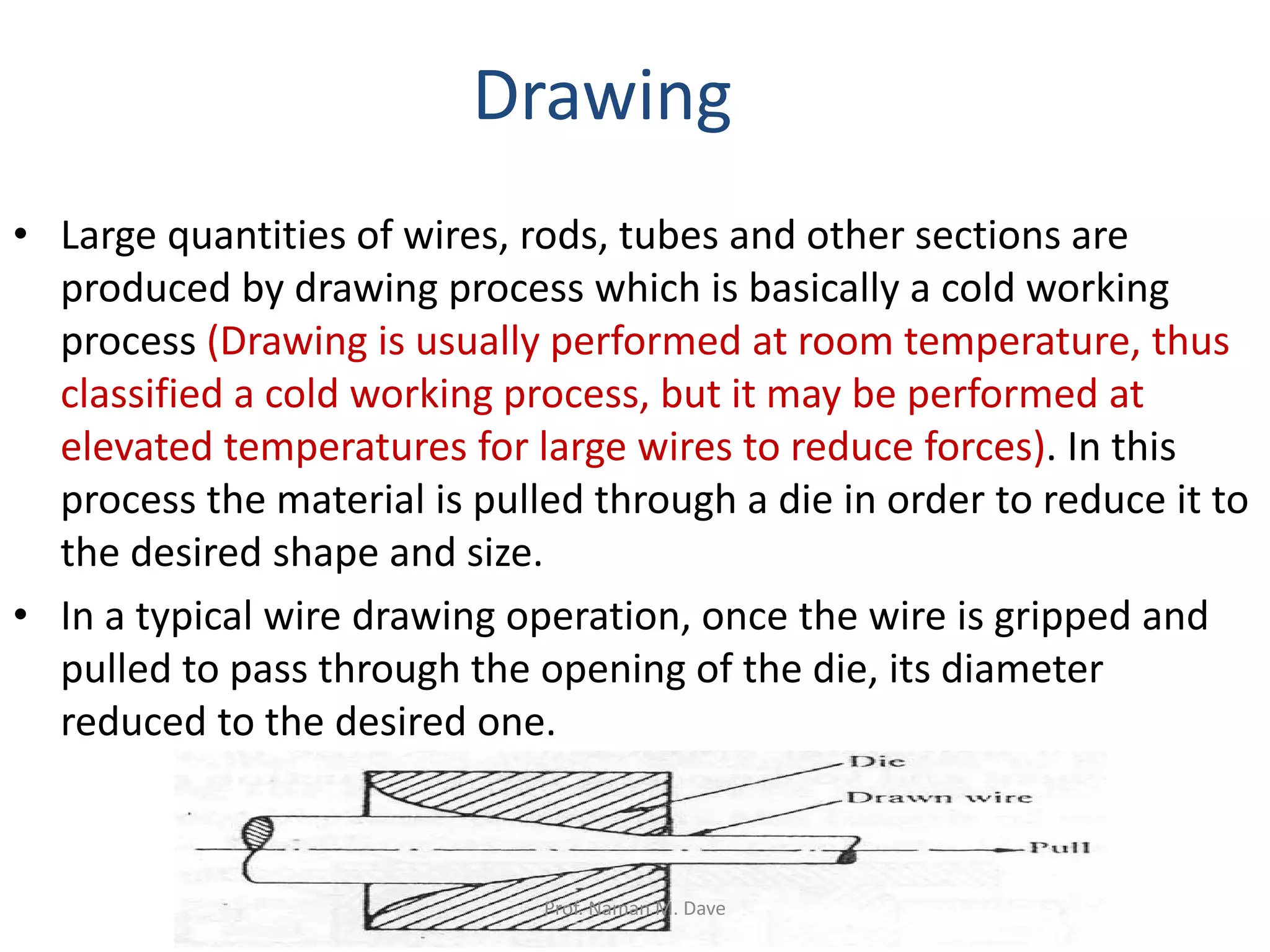


Rod, wire and tube drawing is a metalworking process where a rod, wire or tube is pulled through a die to reduce its cross-sectional area and increase its length. It involves applying both tensile and compressive forces. Products include wire, rods, and tubes used in applications like electrical wiring, springs and hydraulic tubing. The process offers close dimensional control, lower costs than rolling or extrusion, and can produce very small cross-sections. Lubrication and annealing are important to control work hardening during multiple drawing passes. Dies are commonly made of alloy steels, carbides or diamond to withstand wear from the process.


