![3
1. Introduction:
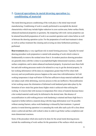
Metal drawing is a manufacturing process to do bulk deformation in metal work is worked
upon to reduce its cross section area. The bulk deformation signifies the massive change in
shape and significant amount of deformation has been done. By forcing the work through a
die (mold) having smaller cross section area than work piece reduction in crossection is
achieved. In the drawing process metal work is drawn through a die by means of tensile force
which is applied at the outlet side. For the work flow through die a reduction in cross
sectional area takes place which results in corresponding increase in length.
The distinction between metal drawing and to metal extrusion process should be clearly
understood that being the force applied. In drawing operation work is being pulled through
the die opening while in extrusion the work is being pushed through the die.
The images below shows the concept and distinction between the two processes.
Image source [10] Metal Drawing
Image source [] A Typical metal drawing operation.
The avg. strain rate is proportional to the reduction in diameter d1/d0, the contact length l and the velocity υ.](https://image.slidesharecdn.com/drawingreportenroll-160407090200/85/A-Report-on-Metal-Drawing-Operations-3-320.jpg)
![4
Image source [26] Metal Extrusion
Factor/ Parameter influencing the nature of product acquired by metal drawing operation
incorporates:
1. Amount of reduction
2. Geometry of cross section
3. Speed at which product is drawn
4. Material nature
a. Yield strength/flow stress.
b. Ductility.
c. Strain hardening.
d. Strain rate sensitivity.
e. Effect of temperature on yield strength and ductility.
f. Effect of hydrostatic pressure on yield strength and ductility.
g. Instability and fracture strength.
5. Temperature of working,
6. Die (mold)
a. Die material
b. Die angle
7. Friction and lubrication
In the process work will start yielding when the force required to pull the work piece through
a die exceeds its yield strength. In metal drawing yielding of work in this way is not desired.
In the process when the force needed to pull the work piece through a die exceeds yield
strength of work, it will start yielding which is undesired. Presence of friction causes
hampering to metal flow, heating and wearing of die, and because of its presence, excess
force needs to be applied. Theoretically the maximum possible amount of area reduction can
be obtained by preventing yielding of the work piece and is usually about 60%. In practice](https://image.slidesharecdn.com/drawingreportenroll-160407090200/85/A-Report-on-Metal-Drawing-Operations-4-320.jpg)
![5
reduction in area range generally from 15% to about 45%. In order to achieve more reduction
in cross section area 2 or more dies are used in corresponding manner. When drawing every
step causes a reduction in cross area region consequently creating an increment long and
therefore a corresponding increase in speed is required in between each step. In wire drawing
methodology to conquer this issue “capstans” are used for both to accommodate the increase
in speed and also to apply tensile stress. To signify the reduction of a round crossection i.e.
difference between initial and final diameter the term ‘draft’ is usually used.
Image source [3] Metal Drawing processes causes
elongation of grain in work
Image source [3] Multi-pass is used get desired
crossection
Image source [3] Some of the products formed by drawing operation](https://image.slidesharecdn.com/drawingreportenroll-160407090200/85/A-Report-on-Metal-Drawing-Operations-5-320.jpg)
![8
Once work is prepared it is worked upon its one end to make it pointed this is done in order
to allow the work to be inserted through the die as die opening is smaller than the original
cross section of bar. The end is then gripped at this end and the work is pulled through.
The last product is generally termed as Cold Finished or Cold Drawn on account of the fact
that the last drawing operation out of the many is always performed cold, this is done to
achieve better surface finish along with lesser resilience and enhanced mechanical properties.
Image source [3] A cross sectional view of die and a rod
Image source [27]
Pointed](https://image.slidesharecdn.com/drawingreportenroll-160407090200/85/A-Report-on-Metal-Drawing-Operations-8-320.jpg)
![9
3. Process description based on the shapes that can be obtained
The metal drawing operation utilises the use of tensile forces for drawing the work. This
process usually involves plastic deformation caused because of drawing through the die
which reduces its cross section area, elongate it in length and extends the work piece grain in
longitudinal course. In the process distinctive cross area states of the metal work piece can be
attained to by changing the pass on likewise tubes can be drawn with the assistance of
mandrel. The shapes of the general drawn products include round and polygonal shapes
which may either be hollow or solid. The metal drawing process for rod, bar, wire and tube
drawing operation has been elucidated below.
Some Tube
Drawing
Products
Some Rod/
Bar Draw
products
Image
source [3]
a. Rod Drawing
Rod drawing (a.k.a. bar drawing) is a metal drawing process in which typically metal of lager
cross section is subjected to compressional forces by a converging die and hence thereby
causing plastic deformation reduction of cross section area. This standard is comparative for
both wire too for bar drawing operation just distinction being in the last cross section area of
the last product. The essential distinction in the middle of wire and bar drawing is last size
cross area of product i.e. if the product is under 5mm it will be prepared through wire
drawing procedure otherwise by bar drawing system are utilized. Other distinction between
these two is the use of greater feed stock if there should arise an occurrence of bar drawing](https://image.slidesharecdn.com/drawingreportenroll-160407090200/85/A-Report-on-Metal-Drawing-Operations-9-320.jpg)
![11
Sinking
Plug Drawing
o Fixed plug
o Floating Plug
Mandrel drawing
Image source [10] In this tube is not provided
with any backing from inside and hence among
the wall thickness, internal and external
diameter only the ED is proper. The use of this
procedure (a.k.a. Tube sinking) is restricted
tubes with small ID.
Image source [10] In this tube is fitted with an
plug and tube is drawn through the hole present in
between the die and the madrel. In this product
take the dimension of of the spacing available in
the middle of plug and die hole.
Image source [10] In this procedure plug is not
attached to mandrel but rather is fitted in by
pushing into tube. The shape of this plug forces
it to stay in that position.
Image source [27] Here plug is not utilized instead
mandrel is constrained into tube. This mandrel and
tube is then pulled from one side.
Various tube drawing process.](https://image.slidesharecdn.com/drawingreportenroll-160407090200/85/A-Report-on-Metal-Drawing-Operations-11-320.jpg)
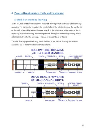
![14
Image source [10] General apparatus of the machines used drawing tubes, rods and bar
b) Wire drawing
In wire drawing operation drawing is done in numerous steps i.e. work is drawn from an
array of dies for the reduction in crossection area. As this process is cold run and higher
amount of strain is required, accordingly in between annealing is done for the removal of
strain hardening. When drawing each step causes a decrease in crossection area thereby
causing an increment in length and therefore a corresponding increment in speed is required
in between each stage. In procedure to overcome this issue “capstans” are used for both to
accommodate the increment in speed and also to apply tensile stress.
Wire drawing equipment working layout](https://image.slidesharecdn.com/drawingreportenroll-160407090200/85/A-Report-on-Metal-Drawing-Operations-14-320.jpg)
![15
Image source [10] Picture above lays out the points of interest for the drawing operation for wire
For wire drawing operation Bull block (a.k.a. rotating draw) is a standard mechanical
assembly. Rotating draw creates a continuous tensile force on drawn wires. This mechanical
assembly is used for drawing very long wires.
Bull Block Apparatus for wire drawing](https://image.slidesharecdn.com/drawingreportenroll-160407090200/85/A-Report-on-Metal-Drawing-Operations-15-320.jpg)
![16
c) Tool- Drawing die
For the industrial purposes dies used based on the requirement for the drawing operation and
cost. Usually mandrel and dies are made up of similar material. Material for die are usually
selected based on the facts given below:
• Tungsten Carbide: cheapest, larger die are accessible, shock resistance, minor life
expectancy, utilized for steel wire drawing.
• Natural Diamond: high thermal conductivity, wear safe, gives magnificent wire
surface, high life expectancy, limited accessibility in desired high quality and amount.
• Synthetic singlecrystal: Larger size extent, dependably a uniform material, high
thermal conductivity and gives incredible wire surface but is pricey right now.
• Polycrystalline Diamond: Shock safe, high life expectancy, Wear safe, cost
adequacy yet may get harmed at a temperature over 700 degree Celsius.
• Additional to this cast iron steel dies are utilized in hot working process. Usually for
the protection of Carbide and steel die are coated with titanium nitride and chromium.
Die design
As the work flow through the mold it passes
through distinctive sections the first section is a
bell opening. It doesn't touch the work however
helps in proper lubrication of the work and allow
for it easy entry in mold without damaging the
die.
After opening bell approach section is there, then
there is bearing surface. Bearing surface hold the
precise geometry for crossection for drawing. In
the end there is exit zone, these are planned in a
manner to protect drawn work.
Image source [10]](https://image.slidesharecdn.com/drawingreportenroll-160407090200/85/A-Report-on-Metal-Drawing-Operations-16-320.jpg)
![17
Image source [27]
d) Some other tools
Pointer- it is utilized to put taper.
Pullin dogs – this is an instrument utilized for grasping the wire end at the way out of
die.
Butt welders – utilized for welding/ joining wire ends](https://image.slidesharecdn.com/drawingreportenroll-160407090200/85/A-Report-on-Metal-Drawing-Operations-17-320.jpg)
![18
5. Load Calculation
a) Analysis of wire drawing
Consider the drawing of a wire through a frustum shaped draw die, as shown below,
Image source [4]. Schematic of wire drawing process
Some of the term associated with wire drawing are:
Area reduction (r) 𝑟 =
(𝐴 𝑜−𝐴 𝑓)
𝐴 𝑜
----------------------1
Drawing ratio (R) 𝑅 = 𝐴 𝑜/ 𝐴𝑓 = 1 ÷ (1 − 𝑟) ---------------------- 2
where, Ao initial cross section area
Af final cross section area
Some of the important parameter of drawing process are:
Strength of work material
Temperature
Speed of drawing
Co-efficient of friction
Die-angle
Reduction of area
Drawing ratio
Approximate expression based on strain energy or plastic deformation energy for drawing
force after ignoring friction and redundant work can be written as:
Draw pressure (p) 𝑝 = 𝑌 ln (
𝐴 𝑜
𝐴 𝑓
) = 𝑌 ln(𝑅) = 𝑌 ln(
1
1−𝑟
) --------------------3
Where, Y average flow stress of the material.
The Draw pressure is independent on draw ratio R.
As draw ratio is increased the draw pressure increases.](https://image.slidesharecdn.com/drawingreportenroll-160407090200/85/A-Report-on-Metal-Drawing-Operations-18-320.jpg)
![19
b) Analysis of wire drawing with friction
Image source [4] Stresses acting on a small elemental section in the drawn body
Let’s consider an element in shape of frustum of the work inside the die.
Where,
As is the circular surface area of the element taken.
a is the half angle of the die.
Ao is the cross area of work at the die entry.
Af is the cross area at the die exit.
Surface area of element can be written as:
𝐴 𝑠 =
𝐴 𝑜−𝐴 𝑓
𝑆𝑖𝑛 𝛼
------------------------------4
Forces acting on the elemental work are:
𝐹𝑜𝑟𝑐𝑒 𝑑𝑢𝑒 𝑡𝑜 𝑛𝑜𝑟𝑚𝑎𝑙 𝑑𝑖𝑒 𝑝𝑟𝑒𝑠𝑠𝑢𝑟𝑒 = 𝑝 𝐴 𝑠 sin 𝛼
𝐹𝑟𝑖𝑐𝑡𝑖𝑜𝑛𝑎𝑙 𝐹𝑜𝑟𝑐𝑒𝑠 = 𝜇 𝑝 𝐴 𝑠 𝐶𝑜𝑠 𝛼
𝐷𝑟𝑎𝑤 𝐹𝑜𝑟𝑐𝑒 = 𝐹
Balancing the force:
𝑝 𝐴 𝑠 sin 𝛼 + 𝜇 𝑝 𝐴 𝑠 𝐶𝑜𝑠 𝛼 = 𝐹 ----------5
Substituting for As from 4, we get:
𝑝 (𝐴 𝑜 − 𝐴𝑓) + 𝜇𝑝(𝐴 𝑜 − 𝐴 𝑓)𝑐𝑜𝑡𝛼 = 𝐹](https://image.slidesharecdn.com/drawingreportenroll-160407090200/85/A-Report-on-Metal-Drawing-Operations-19-320.jpg)
![20
𝐹 = (𝐴 𝑜 − 𝐴𝑓)𝑝[1 + 𝜇𝑐𝑜𝑡𝛼] -------------6
By considering a frictionless drawing operation p can be eliminated.
In absence of friction:
𝐷𝑟𝑎𝑤 𝑓𝑜𝑟𝑐𝑒 = 𝐹 = (𝐴 𝑜 − 𝐴𝑓)𝑝 = 𝑌′
ln (
𝐴 𝑜
𝐴 𝑓
) 𝐴 𝑜
From this, we can write:
𝑝 =
𝐴 𝑜
𝐴 𝑜− 𝐴 𝑓
𝑌′
ln(
𝐴 𝑜
𝐴 𝑓
) ------------7
Substituting 7 in 6, we get:
𝐹 = 𝐴 𝑜 𝑌′
ln(
𝐴 𝑜
𝐴 𝑓
)(1 + 𝜇𝑐𝑜𝑡𝛼) -------------8
Or, the draw stress with friction can be written as:
𝑝 = 𝑌′
ln(
𝐴 𝑜
𝐴 𝑓
)(1 + 𝜇𝑐𝑜𝑡𝛼) -----------------9
It can be seen from the above equation, that draw stress is dependent on the die angle.
It can be inferred from the above equation that higher the die angle, higher the draw stress
required
Schey equation can also be used for measuring the draw stress. It is given as:
𝜎 𝑑 = 𝑌′(1 +
𝜇
tan 𝛼
)𝜃ln(
𝐴 𝑜
𝐴 𝑓
) ------------9A
Where, 𝜃 = 0.88 + 1.2
𝐷
𝐿 𝑐
which accounts for redundant deformation and it is called
inhomogeneity factor.
D is average diameter of the billet,
Lc is contact length of the wire in the die.
𝐿 𝑐 =
𝐷 𝑜−𝐷 𝑓
2 sin 𝛼
and 𝐷 =
𝐷 𝑜+𝐷 𝑓
2
We can determine the draw force from 2.9A as:
𝐹 = 𝐴𝑓 𝜎 𝑑](https://image.slidesharecdn.com/drawingreportenroll-160407090200/85/A-Report-on-Metal-Drawing-Operations-20-320.jpg)
![21
6. Associated Defects and how to dodge them
Defects associated with metal drawing includes:
Internal Cracking: This type of cracks are created due to generation of internal stresses to
which internal breakage of product around centerline may happen. The probable explanation
behind this are the improper flow of metal high die angle as well as low friction
Surface Defect: In these excessive force on surface because of friction wreckage is caused
this happens because of the presence of various micro defects on surface also if operated at
high speed.
Cupping defect: This is observed when in drawn work has uneven crossection. The
conceivable explanation behind this are:
Work is strain hardened to its limit.
Inclusions presence form weak spots.
Draft is too high.
If oil/lubrication wasn't appropriate for the process
Image source [20]
Countermeasures for defects in metal drawing process are:
For the prevention of defect metal flow should be properly controlled.
By the mean of lubrication friction between die and work needs to be tailored
properly
Mold selection should be properly.
Force required to pull the work piece should not exceed the metal yield strength.](https://image.slidesharecdn.com/drawingreportenroll-160407090200/85/A-Report-on-Metal-Drawing-Operations-21-320.jpg)
![22
During Cold working performing low crossection reduction because of this surface of
the drawn part will have compressive residual stress at the surface which will
improves the product life.
Sometime straightening needed to be done which is done using mechanical equipment
Image source [11] Schematic showcasing the straightening1of drawn rod](https://image.slidesharecdn.com/drawingreportenroll-160407090200/85/A-Report-on-Metal-Drawing-Operations-22-320.jpg)
![23
7. References
1. Book: Mechanical Metallurgy, Dieter .G.E.
2. Slide Share
3. Google Images
NPTEL Mechanical Forming Process
4. [link] http://nptel.ac.in/courses/112106153/26
5. [link] http://nptel.ac.in/courses/112106153/27
6. [link] http://nptel.ac.in/courses/112106153/28
Wikipedia
7. [link] http://en.wikipedia.org/wiki/Wire_drawing
8. [link] http://en.wikipedia.org/wiki/Drawing_(manufacturing)
9. [link] http://en.wikipedia.org/wiki/Tube_drawing
Website
10. [link] http://thelibraryofmanufacturing.com/metal_drawing.html
11. [link] http://www.engr.mun.ca/~adfisher/3941/Ch15_Metal-Extr-Drawing-HO.pdf
12. [link]
http://www.sut.ac.th/engineering/Metal/pdf/MetForm/05_Drawing%20of%20rod-
wire%20and%20tubes.pdf
13. [link] http://wwwme.nchu.edu.tw/~CIM/courses/Manufacturing%20Processes/Ch18-
FormingFundamentals-Wiley.pdf
14. [link] http://www.newagepublishers.com/samplechapter/001425.pdf
15. [link] http://www.doitpoms.ac.uk/tlplib/metal-forming-2/printall.php
16. [link] http://engineering.dartmouth.edu/defmech/Chapter_19.htm#Wire, sheet and
tube drawing
17. [link] http://wwwme.nchu.edu.tw/~CIM/courses/Manufacturing%20Processes/Ch18-
FormingFundamentals-Wiley.pdf
18. [link] http://wwwme.nchu.edu.tw/~CIM/courses/Manufacturing%20Processes/Ch18-
FormingFundamentals-Wiley.pdf
19. [link] http://eramandeepbansal.blogspot.in/2012/01/drawing-of-rods-wire-and-
tubes.html
20. [link]
http://www.ganoksin.com/borisat/nenam/prevention_of_defects_in_wrought_alloys.ht
m
21. [link] http://www.ijsrp.org/research-paper-0215/ijsrp-p3864.pdf
22. [link] http://www.wisetool.com/deepdraw.htm
23. [link] http://metalforming-inc.com/Publications/Papers/ref133/ref133-p3.htm
24. [link] http://en.wikipedia.org/wiki/Deep_drawing
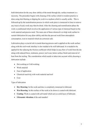
Lubrication
25. [link] http://mct.asu.edu.eg/uploads/1/4/0/8/14081679/lec_5.pdf
26. [link] http://en.wikipedia.org/wiki/Lubricant
27. Images created or modified significantly by me.](https://image.slidesharecdn.com/drawingreportenroll-160407090200/85/A-Report-on-Metal-Drawing-Operations-23-320.jpg)

This document provides an overview of metal drawing operations. It discusses the introduction to drawing, general operations like conditioning materials, process descriptions for shapes like rods/wires and tubes. It covers process requirements including tools, equipment, dies and load calculations. The key points are that metal drawing is a process that uses tensile forces to reduce cross-sectional area and elongate metal by pulling it through a die, important factors include the amount of reduction, speed, material properties and temperature. It can produce various shapes like rods, wires and tubes for different applications.